Load Balancing in LTE Networks
Salvador Navarro Suria
E.T.S.I. Telecomunicaciones Universidad Polit´ecnica de Valencia
A thesis sumitted for the degree of
Master in Telecommunications Engineering
1. Reviewer: Name
2. Reviewer:
Day of the defense:
Self-Optimization will be an integral part of LTE systems in future deployments as part of the Self-Organizing Networks (SON) features defined in 3GPP LTE Re-lease 9 and beyond. In this context, Mobility Load Balancing (MLB) is introduced as a SON use case. MLB enables the optimization of the intra-LTE mobility pa-rameters to the current load in the cell and in the adjacent cells to improve the system capacity compared to static/non-optimised cell reselection/handover pa-rameters. The idea of the MLB use case is to enable cells that suffer congestion to transfer the load to other cells, which have spare resource. Such transfer must usually be forced against (optimal) radio conditions and hence new mechanisms need to be addressed.
The MLB use case goes hand-in-hand with handover procedure, admission con-trol, and other RRM functionalities. It is foreseen that the MLB SON functional-ity will optimize the system performance on a long-term basis as compared to the RRM functionality which adapts the system to network conditions on a millisec-ond basis.
The thesis shall consider the interaction between SON MLB use case and RRM functionalities in order to optimize the system performance. Briefly, the thesis outline may be given as follows:
• Conducted an extensive literature review about RRM and MLB algorithms, identifying current solutions to the problem, and conducting a feasibility analysis for realizing such solutions in real network deployments,
• Getting familiarized with the multi-cell simulator from the company, • Helping in developing and improving an MLB-RRM concept (with direct
• Building a simulation framework for analyzing load balancing and imple-menting a framework (if not already there) for any required information ex-change between the eNBs as required by the investigated solutions,
• Implementing practically relevant load balancing algorithms,
• Evaluating the performance in terms of user throughput, system spectral
ef-ficiency, and other KPIs, and
• Optimizing the algorithms by adapting the parameters and producing final set of results.
Acknowledgements
I would like to acknowledge Abdallah Bou Saleh PhD, for supporting this thesis during the last year. His knowledge has been really helpful on the completion of the thesis and in the discussions while making decisions along the thesis. I also would like to acknowledge Pablo Escalle for speeding up the thesis process and for accepting this Thesis as my final ”Proyecto Final de Carrera” for the Masters degree in Telecommunications Engineering.
List of Figures vii List of Tables xi Glossary xi 1 Introduction 1 2 LTE Overview 3 2.1 General Description . . . 3 2.2 Specifications . . . 4 2.3 Overall Architecture . . . 6
2.3.1 Evolved Packet Core (EPC) . . . 6
2.3.2 Evolved Universal Terrestrial Radio Access Network (E-UTRAN) . . . 7
2.4 Layer 1 : PHY Layer . . . 9
2.5 Layer 2 . . . 13 2.5.1 MAC Sublayer . . . 13 2.5.2 RLC Sublayer . . . 14 2.5.3 PDCP Sublayer . . . 15 2.6 Layer 3 . . . 16 2.6.1 RRC Layer . . . 16 2.6.1.1 System Information . . . 19 2.6.2 RRM Layer . . . 20
2.6.2.1 Quality of Service (QoS) . . . 21
2.7 Interfaces . . . 22
CONTENTS
2.7.2 X2 Interface: . . . 23
2.8 LTE Mobility . . . 24
2.8.1 Mobility management and User Equipment states: . . . 25
2.8.2 Idle mode mobility management: Cell selection and re-selection . . . . 25
2.8.3 Connected mode mobility or Handover: . . . 26
2.8.3.1 X2 Interface: . . . 27
2.8.3.2 S1 Interface: . . . 28
3 Self-Organizing Networks (SON) 29 3.1 Network Management . . . 29
3.2 Self-Organizing Networks (SON) . . . 30
3.3 SON Standardization and use cases . . . 31
3.3.1 NGMN: Next Generation Mobile Networks . . . 31
3.3.2 3GPP and SON Use cases . . . 32
3.4 SON Architecture . . . 34
3.5 SON Challenges . . . 37
4 Mobility Load Balancing (MLB) 39 4.1 Definition . . . 39
4.2 Operational Modes in Mobility Load Balancing . . . 41
4.3 Load balancing mechanism in connected mode . . . 41
4.4 3GPP Standardization evolution of Mobility Load Balancing . . . 42
4.5 Relevant measurements for Load Balancing . . . 43
4.6 Mathematical Framework . . . 45
4.7 Framework for Intra-frequency Load Balancing . . . 47
4.7.1 Overload Detection . . . 47
4.7.2 Load Information exchange for load balancing . . . 48
4.7.3 MLB Decisions . . . 49
4.7.4 Negotiation of mobility/handover parameters: Mobility change Proce-dure . . . 49
5 MLB Algorithm Implementation 51
5.1 Algorithm Implementation Milestones . . . 51
5.2 Mobility Load Balancing States . . . 52
5.3 MLB Monitoring State . . . 53
5.3.1 Virtual Load Implementation . . . 54
5.3.2 Number of unsatisfied Users . . . 55
5.3.3 Composite Available Capacity (CAC) . . . 55
5.4 MLB Reporting State . . . 56
5.5 MLB Balancing State . . . 57
5.5.1 Link Imbalance . . . 62
5.5.2 Load Estimation on Neighbor eNodeB . . . 64
5.5.3 MLB Handover Offset Adjustment . . . 67
6 Results 69 6.1 Amore Simulator . . . 69
6.2 Simulation Scenario Showcase and Parameter Configuration . . . 71
6.3 Performance Evaluation of the MLB Algorithm . . . 71
6.3.1 90 Users Simulations . . . 72 6.3.1.1 90 users: DL CBR 1024/512, UL CBR 1024/512 . . . 72 6.3.1.2 90 users: DL CBR 1024/2048, UL CBR 1024/2048 . . . 74 6.3.1.3 90 users: DL CBR 1800, UL CBR 1800 . . . 76 6.3.2 100 Users Simulations . . . 78 6.3.2.1 100 users: DL CBR 768, UL CBR 768 . . . 80 6.3.2.2 100 users simulations: DL CBR 1024, UL CBR 1024 . . . . 82 6.3.2.3 100 users simulations: DL CBR 1800, UL CBR 1800 . . . . 84 6.3.3 110 Users Simulations . . . 88 6.3.4 Consideration of Simulations . . . 88 6.3.4.1 MLB Gain . . . 88 6.3.4.2 Ratios . . . 93
6.4 Effect of MLB Period on the Performance . . . 93
6.5 Effect of MLB Thresholds on the Performance . . . 96
CONTENTS
7 Conclusion & Future Work 101
7.1 Future Work . . . 102
2.1 LTE Architecture and its terminology . . . 4
2.2 Releases of 3GPP specifications for LTE . . . 5
2.3 LTE and its evolution . . . 5
2.4 Block diagram of LTE Architecture and its evolution . . . 6
2.5 E-UTRAN Protocol Architecture . . . 8
2.6 E-UTRAN Protocol Architecture . . . 8
2.7 OFDM subcarrier spacing . . . 9
2.8 Resource Block . . . 10
2.9 Symbols in a Subframe . . . 11
2.10 OFDMA time frequency multiplexing . . . 11
2.11 Protocol Layer Structure for Downlink . . . 13
2.12 PDCP Layer main packet operations . . . 15
2.13 Protocol Layer review . . . 16
2.14 RRC control over the different Layer . . . 17
2.15 RRC States . . . 18
2.16 Radio Resource Management functions . . . 20
2.17 X2 Protocol Stack . . . 24
2.18 Handover procedure based on X2 Interface . . . 28
3.1 Network Operations . . . 30
3.2 NGMN use cases . . . 32
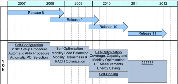
3.3 3GPP SON Standardization evolution . . . 33
3.4 SON Architectures . . . 35
3.5 Real SON Hybrid Architecture . . . 36
LIST OF FIGURES
3.7 SON use cases interrelation . . . 37
4.1 Load Balancing Solution . . . 40
4.2 Required PRBs for 512kbps for a given SINR . . . 46
4.3 Load Balancing Standardized Framework Solution . . . 47
4.4 Load Balancing Thresholds . . . 48
5.1 Mobility Load Balancing States-Machine . . . 52
5.2 Monitoring State Flow Chart . . . 53
5.3 SINR Estimation of unallocated PRBs . . . 54
5.4 Reporting State Flow Chart . . . 56
5.5 MLB Algorithm Flow Chart . . . 58
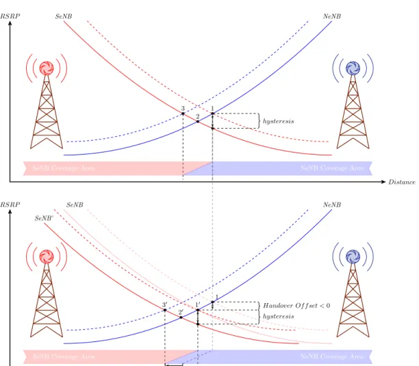
5.6 Effects of Handover Offset decrease . . . 63
5.7 SINR estimation in a Neighbor Cell . . . 65
6.1 DL User Throughput: 90 users CBR1024+512 in DL and UL . . . 73
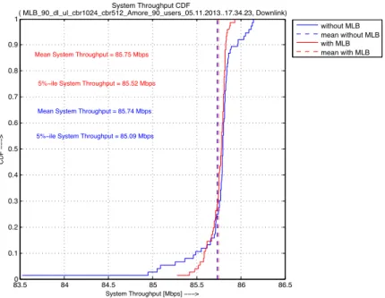
6.2 DL System Throughput: 90 users CBR1024+512 in DL and UL . . . 73
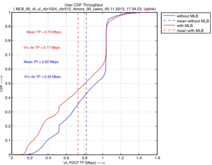
6.3 UL User Throughput: 90 users CBR1024+512 in DL and UL . . . 74
6.4 UL System Throughput: 90 users CBR1024+512 in DL and UL . . . 75
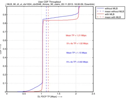
6.5 DL User Throughput: 90 users CBR1024+2048 in DL and UL . . . 75
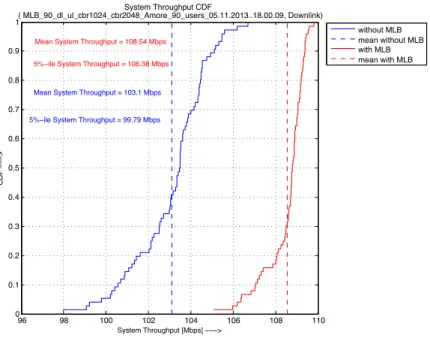
6.6 DL System Throughput: 90 users CBR1024+2048 in DL and UL . . . 76
6.7 UL User Throughput: 90 users CBR1024+2048 in DL and UL . . . 77
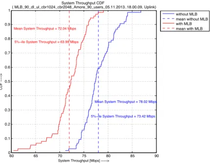
6.8 UL System Throughput: 90 users CBR1024+2048 in DL and UL . . . 77
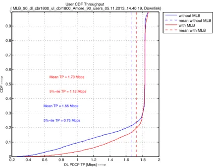
6.9 DL User Throughput: 90 users CBR1800 in DL and UL . . . 78
6.10 DL System Throughput: 90 users CBR1800 in DL and UL . . . 79
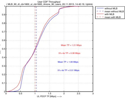
6.11 UL User Throughput: 90 users CBR 1800 in DL and UL . . . 79
6.12 UL System Throughput: 90 users CBR1800 in DL and UL . . . 80
6.13 DL User Throughput: 100 users CBR768 in DL and UL . . . 81
6.14 DL System Throughput: 100 users CBR768 in DL and UL . . . 81
6.15 UL User Throughput: 100 users CBR 768 in DL and UL . . . 82
6.16 UL System Throughput: 100 users CBR768 in DL and UL . . . 83
6.17 DL User Throughput: 100 users CBR1024 in DL and UL . . . 83
6.18 DL System Throughput: 100 users CBR1024 in DL and UL . . . 84
6.20 UL System Throughput: 100 users CBR1024 in DL and UL . . . 85
6.21 DL User Throughput: 100 users CBR1800 in DL and UL . . . 86
6.22 DL System Throughput: 100 users CBR1800 in DL and UL . . . 86
6.23 UL User Throughput: 100 users CBR 1800 in DL and UL . . . 87
6.24 UL System Throughput: 100 users CBR1800 in DL and UL . . . 87
6.25 90 users: DL mean user Throughput Gain . . . 88
6.26 90 users: DL mean System Throughput Gain . . . 89
6.27 90 users: DL 5%-ile user Throughput Gain . . . 90
6.28 90 users: DL 5%-ile System Throughput Gain . . . 90
6.29 110 users: DL mean user Throughput Gain . . . 91
6.30 110 users: DL mean System Throughput Gain . . . 91
6.31 90 users: UL mean System Throughput Gain . . . 92
6.32 110 users: UL mean System Throughput Gain . . . 93
6.33 DL mean System Throughput for different MLB Periods . . . 94
6.34 UL mean System Throughput for different MLB Periods . . . 95
6.35 Effect of MLB Threshold in the DL System Throughput with 90 users . . . 96
6.36 Effect of MLB Threshold in the DL System Throughput with 120 users . . . . 97
6.37 Effect of the SINR tuning in the DL System Throughput with 100 users . . . . 99
2.1 Number of Resource Blocks for different System Bandwidth . . . 12
2.2 System Information Blocks . . . 19
2.3 System Information Blocks Parameters . . . 19
2.4 Service QCI Characteristics . . . 22
Introduction
This thesis discuss the Mobility Load Balancing functionality described on the 3GPP standard for Long Term Evolution (LTE) Networks. This functionality belongs to the set of functional-ities available for self-organizing Networks (SON) and applies its enhancements in the Radio Resource Management (RRM) layer of the LTE protocol stack.
The discussion starts with an introduction to the LTE Radio System and its protocol stack. The properties of each layer are summarized in Chapter 2. The goal of this introduction is to give a general overview of the system and explain some characteristics of the system, as well as concepts, that apply directly to the framework of this thesis. If further details is needed, the bibliography is provided at the end of the thesis.
Chapter 3 will introduce Self-Organizing Networks and discuss the need for automated solutions on the network to enhance the network performance and reduce costs. The present 3GPP standard and special features available for SON will be explained for the self-optimizing solutions and specially for the Mobility Load Balancing capabilities standardized in the differ-ent releases.
Chapter 4 will define and discuss in detail the framework necessary to implement the Mo-bility Load Balancing solution. We will take a look at the mathematical framework developed for MLB and the parameters and assumptions necessary to consider for the solution.
Chapter 5 explains the solution chosen and implemented in this thesis. We will take a look at the details of the MLB algorithms and explain how the decision process takes place and which approximations were made to solve the problems for a real system solution.
Chapter 6 will introduce the simulator (AMoRE) used to evaluate the performance of the MLB algorithm. It will discuss the results obtained for different scenarios pointing out the
1. INTRODUCTION
cases where the MLB solution is appropriate and showing the dependency of the performance to the parameters introduced in the MLB algorithm.
Finally, chapter 7 will give an overview of the results obtained for the MLB algorithm and will propose new paths to research to enhance the performance of the MLB algorithm and the performance of the system.
LTE Overview
The objective of this chapter is to present an overview of the UMTS Long Term Evolution (LTE) to have some background information and a better understanding of the whole Mobile Communication system. This overview will help understand some of the concepts introduced in further chapters. The following sections are a collection of notes taken from different books and do not describe the system in depth. For a more detailed description, refer to the books appointed in the bibliography.
2.1 General Description
Long Term evolution is a 3GPP project and the last step in the evolution of mobile communi-cations systems which extends and modifies UMTS systems. Figure 2.1 show a first represen-tation of the LTE architecture and explains graphically the terminology that would be used in the architecture description.
LTE is developed under the assumption that all the services are packet based and therefore the radio access technology, as well as the core network (EPC : Evolved Packet Core), are fully packet-switched (PS) with IP connectivity. Together, LTE and EPC, constitute the Evolved Packet System (EPS) which defines a new network architecture that allows the following en-hancements:
• A Simple and Flat architecture that favors an optimized usage of the network and mini-mizes the number of network elements. Due to the fact that all radio network function-alities are located at the eNodeB, there is no need for extra controllers as in UMTS.
2. LTE OVERVIEW
LTE Architecture/Terminology
!!" #$%&'()*+,-$.,/ # 01 ! #0 # 01! ! #01!! " 01# #01 2 EPC(Evolved packet Core) MME (Mobility Management Entity) LTE Architecture 4 $34 $34 $34 ! ! " 12 ! ! " 56 56 56 "127893 12
(Evolved UMTS Terrestrial Radio Access Network) EPS (Evolved Packet System) eNB (evolved Node B) UE User Equipment
Figure 2.1: LTE Architecture and its terminology- See
• High Data Rate reached due to advanced modulation techniques for optimization of radio
frequencies.
• Packet Optimized radio access network
• Enhance User experience for High quality multimedia services by improving cell capac-ity, end-user throughput and low user plane latency
In the following sections we will be taking a closer look to the EPS system with a brief descrip-tion of the EPC core network as part of the whole system and we will explain in more detail the E-UTRAN.
2.2 Specifications
The 3GPP ( 3rdGeneration Partnership Project) is a collaborative standardization group formed
by several telecommunication associations from different parts of the world and member com-panies who participate in the standardization process. The 3GPP establish the specifications of the E-UTRAN (Evolved UMTS Terrestrial Radio Access Network), their aim is to guarantee interoperability between multiple vendors, adapt the system to the regulations of the different
2.2 Specifications
countries and take into consideration the market needs when defining these specifications. In figure 2.2 and 2.3, we can see the last LTE releases with some of their features.
During the fall of 2005, 3GPP TSG RAN WG1 made extensive studies of different basic physical layer technologies and in December 2005 the TSG RAN plenary decided that the LTE radio access should be based on OFDM in the downlink and DFT-precoded OFDM in the uplink. TSG RAN and its working groups then worked on the LTE specifications and the specifications were approved in December 2007. Work has since then continued on LTE, with new features added in each release, as shown in Figure 1.6. Chapters 7–17 will go through the details of the LTE radio interface in more detail.
Rel-11 2 nhanced carrier aggregation 2Additional intra-band carrier aggregation Rel-10 (March 2011) “LTE-Advanced” 2Carrier aggregation 2 (#( )0(&$(% MIMO 2 *&$(% 2 (#( 2Relays Rel-9 December 2009 2 )' ) 2Location Services 2 ,.**)+t 2 .&-$,-(+ Rel-8 December 2008
First release for 2 2
FIGURE 1.6
Releases of 3GPP specifications for LTE.
2009 2010 2011 2008 ITU-R Proposals Evaluation Evaluation Specification
Circular letter Submission of IMT-Advanced candidates IMT-Advanced standard LTE-Advanced workshop 3GPP Study Item ITU submission
ready Final submission (“LTE-Advanced”)LTE release 10
Proposals
Specification
Study Item Work ItemWork Item
FIGURE 1.7
3GPP time schedule for LTE-Advanced in relation to ITU time-schedule on IMT-Advanced. Figure 2.2: Releases of 3GPP specifications for LTE- See (1) 96 CHAPTER 7 LTE Radio Access: An Overview
7.1 BASIC PRINCIPLES
Building upon the basic technologies described in the previous chapters, the main principles behind LTE will be described in the following.
7.1.1 Transmission Scheme
The LTE downlink transmission scheme is based on conventional OFDM. As discussed in Chapter 3, OFDM is an attractive transmission scheme for several reasons. Due to the relatively long OFDM symbol time in combination with a cyclic prefix, OFDM provides a high degree of robustness against channel frequency selectivity. Although signal corruption due to a frequency-selective channel can, in principle, be handled by equalization at the receiver side, the complexity of such equalization starts to become unattractively high for implementation in a terminal at larger bandwidths and especially in combination with advanced multi-antenna transmission schemes such as spatial multiplexing, thereby making OFDM an attractive choice for LTE for which a wide bandwidth and support for advanced multi-antenna transmission were key requirements.
OFDM also provides some additional benefits relevant for LTE:
Basic LTE functionality Enhancements & extensions Further enhancements & extensions IMT-Advanced compliant Rel-9 Rel-10 Rel-8 FDD and TDD support Bandwidth flexibility ICIC Multi-antenna support
Channel-dependent scheduling Hybrid ARQ OFDM transmission
MBMS Carrier Aggregation
Relaying Multi-antenna extensions Dual-layer beam forming
Positioning
FIGURE 7.1
LTE and its evolution. Figure 2.3: LTE and its evolution- See (1)
The first LTE requirements were defined in mid 2005 and the first LTE standardization was finalized in december 2008, know as Release 8. LTE has been enhanced and further standard-izations have been made during the last years through releases 9 and 10. At the moment, release 11 is being standardized by the 3GPP. See section 1.5 of (Dahlman et al.(1) )for further details on 3GPP and the standardization process.
2. LTE OVERVIEW
2.3 Overall Architecture
Figure 2.4, takes a closer look at the LTE architecture and the interfaces between the different entities.
Overall LTE Architecture
LTE Architecture 11
HSS Home Subscriber Server
HLR Home Location Register
AuC Authorization Center
PCRF Policy and Charging Rules Function
PDN Packet Data Network
Figure 2.4: Block diagram of LTE Architecture and its evolution
-2.3.1 Evolved Packet Core (EPC)
The EPC as explained in (2), supports only access to the packet switched domain, meaning that it doesnt have support for the circuit switched domain. The EPC contains all functional core network entities . This entities are grouped into control plane entities and user plane entities, that is, MME, HSS and PCRF for the first case and S-GW together with P-GW in the second case . Here is a short explanation of the different entities from the Control and User Plane and some of their more important aspects.
Mobility Management Entity(MME): The MME is the central element of the EPC, it uses a direct logical control plane connection to support the following functions:
• Mobility Management: In Idle and Active mode, UE tracking, MME selection and mo-bility between 3GPP access networks
• Authentication and security through NAS signaling
• Management of subscription profile and service connectivity
• Packet core Bearer management functions including dedicated bearer establishment
Home Subscriber Server (HSS) : database that stores subscriber data such as User iden-tification, addressing and the user-specific security credentials needed for authentication and ciphering.
Policy and charging rules function(PCRF): responsible for quality-of-service (QoS) han-dling, Interfaces with the PDN gateway to convey policy decisions to it and charging.
Serving Gateway(S-GW): provides tunneling management between P-GW and eNodeB and switching with some control functions:
• Mobility anchor for inter-3GPP mobility
• Packet routing, forwarding and buffering
• Downlink rate enforcement based on aggregate maximum bit rate (AMBR)
Packet Data Network Gateway(P-GW): is the router that looks to the outside world (Inter-net). Its main functions are:
• User Equipment IP allocation and routing • Per user packet filtering
• Charging for UL/DL per UE, per PDN and QoS Class Identifier • Mobility to non-3GPP RATs.
As shown before in figure 2.1, the S1 interface connects the E-UTRAN with the MME through S1-MME and with the S-GW through the S1-U.
2.3.2 Evolved Universal Terrestrial Radio Access Network (E-UTRAN)
The 3GPP specification (3), gives an overall description of the E-UTRAN. The E-UTRAN is based on a single radio access entity called eNodeB . The eNodeB (eNB) holds all the network functionalities and therefore there is no need for a centralized controller as the RNC (Radio Network Controller) in UMTS. With no separated control entity of the Radio access, the TTI
2. LTE OVERVIEW
(Transmission Time Interval) is much shorter than in UMTS allowing a very fast adaptation to the radio environment as well as a very flexible and fast access during handover. This configuration of the radio access permits to have a distributed architecture which reduces the complexity of the whole system. Thus, the Radio Access Network is composed of a mesh of eNodeBs connected to each other through the X2 interface with IP connectivity allowing good scalability of the network, reuse of the backhaul infrastructure and avoidance of single points of failure. The E-UTRAN also define a separation between User Plane and Control Plane which make them independent from each other. This fact influence the latency of the system by lowering it and allows a better scalability.
Figures 2.6 and 2.5 show the differences and similarities between the User Plane and the
Control Plane. 2.1 Network architecture 7
eNB PDCP PHY MAC RLC Gateway IP UE PDCP PHY MAC RLC IP
Figure 2.3. User plane protocol.
eNB PDCP PHY MAC RLC MME NAS UE PDCP PHY MAC RLC NAS RRC RRC
Figure 2.4. Control plane protocol stack.
the network side are now terminated in eNB. The functions performed by these layers are described in Section 2.2.
Figure 2.4 shows the control plane protocol stack. We note that RRC functionality traditionally implemented in RNC is now incorporated into eNB. The RLC and MAC layers perform the same functions as they do for the user plane. The functions performed by the RRC include system information broadcast, paging, radio bearer control, RRC connection management, mobility functions and UE measurement reporting and control. The non-access stratum (NAS) protocol terminated in the MME on the network side and at the UE on the terminal side performs functions such as EPS (evolved packet system) bearer management, authentication and security control, etc.
The S1 and X2 interface protocol stacks are shown in Figures 2.5 and 2.6 respectively. We note that similar protocols are used on these two interfaces. The S1 user plane interface (S1-U) is defined between the eNB and the S-GW. The S1-U interface uses GTP-U (GPRS tunneling protocol – user data tunneling) [2] on UDP/IP transport and provides non-guaranteed delivery of user plane PDUs between the eNB and the S-GW. The GTP-U is a relatively simple
Figure 2.5: E-UTRAN Protocol Architecture- User Plane
2.1 Network architecture 7 eNB PDCP PHY MAC RLC Gateway IP UE PDCP PHY MAC RLC IP
Figure 2.3. User plane protocol.
eNB PDCP PHY MAC RLC MME NAS UE PDCP PHY MAC RLC NAS RRC RRC
Figure 2.4. Control plane protocol stack.
the network side are now terminated in eNB. The functions performed by these layers are described in Section 2.2.
Figure 2.4 shows the control plane protocol stack. We note that RRC functionality traditionally implemented in RNC is now incorporated into eNB. The RLC and MAC layers perform the same functions as they do for the user plane. The functions performed by the RRC include system information broadcast, paging, radio bearer control, RRC connection management, mobility functions and UE measurement reporting and control. The non-access stratum (NAS) protocol terminated in the MME on the network side and at the UE on the terminal side performs functions such as EPS (evolved packet system) bearer management, authentication and security control, etc.
The S1 and X2 interface protocol stacks are shown in Figures 2.5 and 2.6 respectively. We note that similar protocols are used on these two interfaces. The S1 user plane interface
Figure 2.6: E-UTRAN Protocol Architecture- Control Plane
In the following sections, we will be explaining some of the functionalities of the different layers for a better understanding of the E-UTRAN protocol stack.
2.4 Layer 1 : PHY Layer
The E-UTRAN is a very flexible air interface, it supports both frequency division duplex (FDD) and time division duplex (TDD) modes of operation. Thus, most of the design parameters are common to TDD and FDD modes to reduce the complexity of the terminal.
In downlink, LTE uses a new multiple access technology called OFDMA (Orthogonal Fre-quency Division Multiple Access ) which is an extension of OFDM for multi-user communi-cation systems that utilize the spectrum in a more efficient manner than WCDMA in UMTS. OFDM (Orthogonal Frequency Division Multiplexing) is a special case of FDM where the car-riers are all made orthogonal with the help of a Fourier transform. This leads to the ability of squeezing subcarrier really tight together. Figure 2.7 shows an example of OFDM subcarrier spacing.
28 CHAPTER 3 OFDM Transmission
that, during each OFDM symbol interval, Nc modulation symbols are transmitted in parallel. The
modulation symbols can be from any modulation alphabet, such as QPSK, 16QAM, or 64QAM. The number of OFDM subcarriers can range from less than hundred to several thousand, with the subcarrier spacing ranging from several hundred kHz down to a few kHz. What subcarrier spacing to use depends on what types of environments the system is to operate in, including such aspects as the maximum expected radio-channel frequency selectivity (maximum expected time dispersion) and the maximum expected rate of channel variations (maximum expected Doppler spread). Once the subcarrier spacing has been selected, the number of subcarriers can be decided based on the assumed overall transmission bandwidth, taking into account acceptable out-of-band emission, etc.
∆f 2 ∆f 3 ∆f 4 ∆f –4 ∆f –3 ∆f –2 ∆f –∆f 0 Tu= 1/∆f ( ) ( ) 2 sin f/∆f f/∆f π π Pulse-shape Sub-carrier spectrum Time domain (a) Frequency domain (b) FIGURE 3.1
(a) Per-subcarrier pulse shape. (b) Spectrum for basic OFDM transmission.
∆f = 1/Tu
FIGURE 3.2
OFDM subcarrier spacing.Figure 2.7: OFDM subcarrier spacing
-In LTE, the subcarrier spacing is standardized to f =15 KHz which is a compromise
between the overhead of the CP (Cyclic Prefix), used to reduce ISI (Inter-symbol Interfer-ence) due to multi-path propagation, and the sensitivity to frequency offsets due to Doppler spread/shift which produces ICI (Inter-Carrier Interference) breaking the orthogonality of the subcarriers.
As described in (2), the smallest transmission unit are Resource Elements. Each Resource Element contains a symbol of durationTsym = 66.67µstransmitted over a single sub-carrier
of f =15 KHz, the number of bits per symbol depend on the modulation scheme used e.g.
QPSK, 16QAM or 64QAM. The Downlink and Uplink are divided into Physical Resource Blocks (PRBs), see Figure 2.8, each Resource Blocks (RB) contains 12 consecutive subcarrier and 6 or 7 symbols (depending on the lenght of CP) per subcarrier transmitted in a slot(0,5 ms).
2. LTE OVERVIEW
2.4 Layer 1 : PHY Layer
Figure 2.9, explains graphically a subframe, a subframe is the combination of two resource blocks equivalent that occupy 2 slots and a total of 2 RB x (12 subcarriers x 7 symbols), that is 168 Resource Elements. A TTI (Transmission Time Interval) is the smallest scheduling
41<2+*212=*$=*2+.*>$%?$@A122<23$125$";+<4<B1+<-2$C*4<%1D+-41+*5$,<+E$
ED412$<2+*.1=+<-2$:E<3E$"@FGH$*..-.CH$E<3E$*I;*.+<C*>$
%
$
%
&'J$-;*.1+-.C$K1=*$-;*.1+<-21A$=E1AA*23*C$<2$+*.4C$-K$,-./$*KK-.+$125$=-C+$
%
&'J$F1.A7%@E1C*C)$C*+%D;H$-;+<4<B1+<-2$;.-5D=*$5*A17C$$+E1+$!"#$+.<*C$+-$
4<2<4<B*$1C$,*AA$1C$+E*$-;*.1+<-21A$*I;*25<+D.*C$:"@FG>H$*I;*2C*C$+E1+$,<AA$
2-+$=-4;*2C1+*5$67$+E*$.*L*2D*$K.-4$+E*$DC*.C$5D*$+-$41./*+<23$C+.1+*3<*C$
125$K<*.=*$=-4;*+<+<-2$<2$;.<=<23'$
%
&'&$0*12$+-$<2=.*1C*$1D+-41+<-2$-K$2*+,-./$-;*.1+<-2C$)$.*5D=*$
";*.1+<-21A$*KK-.+H$;.-+*=+$+E*$2*+,-./$K.-4$*..-.CH$C;**5<23$D;$
-;*.1+<-21A$;.-=*CC*C$$
%
&'&$!"#$C+1251.5C$5*K<2*$DC*$=1C*CH$4*1CD.*4*2+CH$;.-=*5D.*C$125$-;*2$
<2+*.K1=*C$+-$CD;;-.+$<2+*.-;*.16<A<+7$<2$4DA+<%L*25-.$*2L<.-24*2+$1A-23$<2$
M*A%NHM*A%OH$M*A%&JHM*A%&&$
%
&'P$";+<4<B*5$C*++<23C$-K$*L*.7$<25<L<5D1A$;1.14*+*.$<2$*1=E$2*+,-./$
*A*4*2+$
%
Q$;1.+C)$
o
!*AK$9-2K<3D.1+<-2$
o
!*AK%$";+<4<B1+<-2$
o
!*AK%R*1A<23$
0ST$
$
P'U'V$%$
The objective of load balancing is to counteract local traffic load imbalance betweenneighbouring cells with the aim of improving the overall system capacity
$
SWF$0*1CD.*4*2+C$
M!M@$
M!MX$
YTM$
$
222 From GSM to LTE t Frequency = 1 symbol = 1 resource element (15 kHz) 1 Resource block = 1 slot (0.5 ms) = 12 subcarriers × 7 symbols 180 kHz 1 Frame (10 ms) = 10 subframes (1ms) = 20 slots (0.5 ms) Next frame1 Subframe
Figure 4.7 LTE resource grid. Reproduced from Beyond 3G – Bringing Networks, Terminals and the Web
Together, Martin Sauter, 2009, John Wiley and Sons Ltd.
1 Subframe = 2 resource blocks= 2 slots (0.5 ms) =
2 × (12 subcarriers × 7 symbols) = reference signal
Figure 4.8 Symbols in a resource block used for the reference signal.
pattern over the entire channel bandwidth. Reference signals are inserted on every seventh symbol on the time axis and on every 6th subcarrier on the frequency axis as shown in Figure 4.8. Details are given in 3GPP TS 36.211 [14]. A total of 504 different reference signal sequences exist, which help a mobile device to distinguish transmissions of different base stations. These patterns are also referred to as the Physical Cell Identity (PCI). Neighboring base stations need to use different symbols for the reference signals for the mobile device to properly distinguish them. Hence, six PCI groups have been defined, each shifted by one subcarrier.
For initial synchronization, two additional signal types are used. These are referred to as the primary and secondary synchronization signals and they are transmitted in every first and sixth subframe on the inner 72 subcarriers of the channel. On each of those subcarriers, one symbol is used for each synchronization signal. Hence, synchronization signals are transmitted every 5 milliseconds. Further details can be found in Section 4.6.1 where the initial cell search procedure is described.
222 From GSM to LTE t Frequency = 1 symbol = 1 resource element (15 kHz) 1 Resource block = 1 slot (0.5 ms) = 12 subcarriers × 7 symbols 180 kHz 1 Frame (10 ms) = 10 subframes (1ms) = 20 slots (0.5 ms) Next frame
1 Subframe
Figure 4.7 LTE resource grid. Reproduced from Beyond 3G – Bringing Networks, Terminals and the Web
Together, Martin Sauter, 2009, John Wiley and Sons Ltd.
1 Subframe = 2 resource blocks= 2 slots (0.5 ms) =
2 × (12 subcarriers × 7 symbols) = reference signal
Figure 4.8 Symbols in a resource block used for the reference signal.
pattern over the entire channel bandwidth. Reference signals are inserted on every seventh symbol on the time axis and on every 6th subcarrier on the frequency axis as shown in Figure 4.8. Details are given in 3GPP TS 36.211 [14]. A total of 504 different reference signal sequences exist, which help a mobile device to distinguish transmissions of different base stations. These patterns are also referred to as the Physical Cell Identity (PCI). Neighboring base stations need to use different symbols for the reference signals for the mobile device to properly distinguish them. Hence, six PCI groups have been defined, each shifted by one subcarrier.
For initial synchronization, two additional signal types are used. These are referred to as the primary and secondary synchronization signals and they are transmitted in every first and sixth subframe on the inner 72 subcarriers of the channel. On each of those subcarriers, one symbol is used for each synchronization signal. Hence, synchronization signals are transmitted every 5 milliseconds. Further details can be found in Section 4.6.1 where the initial cell search procedure is described.
$
Figure 2.9: Symbols in a Subframe - 2 Resource Blocks in a TTI. See (4)time in LTE equivalent to 1 ms, equivalent to one subframe or 2 resource blocks. During
the scheduling time or TTI the eNodeB decides to which user should be scheduled and which resource blocks are assigned to each one.
Figure 2.10 shows the downlink physical layer design and the assignment to different UEs
. LTE/E-UTRA
Figure 7 OFDMA time-frequency multiplexing (example for normal cyclic prefix)
Downlink control channels
The Physical Downlink Control Channel (PDCCH) serves a variety of purposes. Primarily, it is used to convey the scheduling decisions to individual UEs, i.e. scheduling assignments for uplink and downlink. The PDCCH is located in the first OFDM symbols of a subframe. For frame structure type 2, PDCCH can also be mapped onto the first two OFDM symbols of DwPTS field.
An additional Physical Control Format Indicator Channel (PCFICH) carried on specific resource elements in the first OFDM symbol of the subframe is used to indicate the number of OFDM symbols for the PDCCH (1, 2, 3, or 4 symbols are possible). PCFICH is needed because the load on PDCCH can vary, depending on the number of users in a cell and the signaling formats conveyed on PDCCH.
The information carried on PDCCH is referred to as downlink control information (DCI). Depending on the purpose of the control message, different formats of DCI are defined. As an example, the contents of DCI format 1 are shown in Table 5. DCI format 1 is used for the assignment of a downlink shared channel resource when no spatial multiplexing is used (i.e. the scheduling information is provided for one code word only). The information provided contains everything what is necessary for the UE to be able to identify the resources where to receive the PDSCH in that subframe and how to decode it. Besides the resource block assignment, this also includes information on the modulation and coding scheme and on the Figure 2.10: OFDMA time frequency multiplexing - See (5)
2. LTE OVERVIEW
Since LTE is a very flexible system, the number of PRBs available depends on the Band-width of the whole system. As explained in (1), the OFDM falls off very slowly out of the OFDM Bandwidth therefore a 10% guard band is needed. That means that out of a 5 MHz Bandwidth, 4.5 MHz will be actually used for transmission of Resource Blocks. Table 2.1 shows the number of resource blocks depending on the system bandwidth.
Bandwidth Sub-carriers Resource Blocks
1.4 MHz 75 6 3 MHz 180 15 5 MHz 300 25 10 MHz 600 50 15 MHz 900 75 20 MHz 1200 100
Table 2.1: Number of Resource Blocks for different System Bandwidth.
In the Uplink, OFMA is not an optimum solution due to the weak peak-to-average power ratio (PAPR) properties of the signal. Instead, SC-FDMA (Single Carrier Frequency Division Multiple Access) with cyclic prefix is used because of its better PAPR properties. It also allows a lower cost of the UE terminals, due to the usage of cheaper power amplifiers, as well as a lower power consumption enlarging the battery life at the UE . The Uplink layer design is the same as in Downlink so the same explanations done before applies also for the uplink case.
From a functional perspective, the role of the PHY Layer is to provide physical channels to the upper RLC and MAC layers. As described in (6), the TTI is a transport channel attribute and can be explicitly given by higher layers through the modulation, the coding scheme and the size of the transport blocks. At each TTI, the physical layer receives a certain number of Transport Blocks for transmission then a CRC (Cyclic Redundancy Check) is added, then protected by a channel-encoding scheme and size adapted by the MAC HARQ process. Moreover, the interleaving process takes place to make it more robust to errors and the Mac layer decides about modulation scheme and finally the data is mapped to the different control or data physical channels.
2.5 Layer 2
2.5 Layer 2
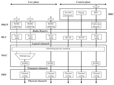
Figure 2.11, shows the 3 sublayers contained in Layer 2 and the channel interfaces between each other, Layer 1 and Layer 3:
4.3.1 The E-UTRAN Radio Layered Architecture
Figure 4.11, which introduces some new vocabulary, is an overview of radio protocol structure, which is further described in the next section. It briefly describes the main purpose of the different layers and how they interact with each other. This picture only describes the protocol layering on the eNodeB side, but there, of course, exist similar – or dual – functions and layers on the terminal side.
Starting from the top of the picture, the RRC layer (Radio Resource Control) supports all the signalling procedures between the terminal and the eNodeB. This includes mobility procedures as well as terminal connection management. The signalling from the EPC Control plane (e.g. for terminal registration or authentication) is transferred to the terminal through the RRC protocol, hence the link between the RRC and upper layers.
ThePDCPlayer (whose main role consists of header compression and implementation of security such as encryption and integrity) is offered to Radio Bearers by E-UTRAN lower layers. Each of these bearers corresponds to a specific information flow such as User plane data (e.g. voice frames, streaming data, IMS signalling) or Control plane signalling (such as RRC or NAS signalling issued by the EPC). Due to their specific purpose and handling, information flows generated bySystem Information BroadcastandPagingfunctions are transparent to the PDCP layer.
PDCP RLC MAC Multiplexing PHY ROHC ciphering Segm. ARQ ROHC ciphering ROHC ciphering Segm. ARQ Segm. ARQ Transport channels Physical channels Logical channels Radio Bearers HARQ Scheduling/priority handling HARQ Channel coding Channel coding Channel coding Channel coding RRC Segm. ARQ HARQ Channel coding Control plane User plane RRC Paging Sys Info broadcast BCCH PCCH Ciphering integrity
Figure 4.11 Protocol layered structure in eNodeB for downlink channels. Figure 2.11: Protocol Layer Structure for Downlink - See (6)
The different sublayers and their functions will be explained briefly in the following sub-sections. For further details on the specifics of each function, please refer to the books cited in the bibliography or the 3GPP specification.(1, 2, 6)
2.5.1 MAC Sublayer
The Medium Access Control (MAC) radio protocol sublayers main purpose is to provide an efficient coupling between RLC services and the physical layer. The main function for the MAC sublayer are:
• Multiplexing of Radio Bearers (Signaling and Data Bearers) : Mapping between Logi-cal channels and transport channels, logiLogi-cal channel identification and transport format selection, reference signals, synchronization signals, broadcast channel and HARQ indi-cator channel.
2. LTE OVERVIEW
• HARQ (Hybrid Automatic Retransmission reQuest): used for Error Correction and al-lows the network to retransmit faulty packets
• Dynamic Scheduling (UL/DL): decides when, where and what kind of data is scheduled
and to which UE the data is sent.
• Priority Handling: between UEs and between logical channels • QoS Management
• Timing Advance: for synchronization of the mobile transmission
• MAC Control Messaging : PDCCH indicate which resource blocks are allowed to use in
the uplink direction (Uplink packet scheduling ),
• Power headroom report (UL)
• Buffer Status Report (PUSCH) • Padding
The MAC layer connects with the RLC over the logical channels, for a better explanation on how the mapping of the logical and transport channels is done, please refer to the 3GPP specification (3) .
2.5.2 RLC Sublayer
The main goal of the Radio Link Control sublayer is to receive and deliver data packet to its peer RLC entity. For that purpose, three different transmission modes are available and assigned to the different logical channels depending on the type of information they carry:
• Transparent Mode ( TM ): used for general information, it does not alter the upper layer
data, no RLC header, just forwards the data.
• Unacknowledged Mode (UM) used for signaling.
• Acknowledge Mode (AM) used for user data.
The main functions of RLC sublayer are performed depending on the transmission mode (UM or AM ):
• Segmentation : decides on PDU sizes depending on QoS and available resources
• Automatic Repeat reQuest (ARQ) : ensures the correct delivery of data for AM mode
over the air interface.
• Reassembly: (UM and AM ) it needs a RLC header in the PDU to know the order of the sequence
• Status Report (AM): indicates if retransmission was lost. 2.5.3 PDCP Sublayer
Figure 2.12, shows the functionality of the Packet Data Convergence Protocol (PDCP) Layer:
PDCP Layer
Control Plane Integrity Protection User Plane PDCP ROHC Buffer Buffer NAS Sequence Numbering Sequence Numbering
!
Header compression can run in non compressed mode
Protection
Add header Add header
data_req data_ack RLC
Ciphering Ciphering (optional)
LTE Protocol Overview Confidential 63
Figure 2.12: PDCP Layer main packet operations
-The main functions of the PDCP Layer are :
• Encapsulation of higher layer protocols
• Packet handling: Buffers packets until they are scheduled by lower layers • Packet forwarding :Lossless Retransmission of PDCP SDU to support Handover
• Queuing: AQM (Active Queue Management) controls the length of the queues and the
2. LTE OVERVIEW
As seen in the figure 2.12, the User plane uses RObust Header Compression (ROHC) and encryption (Data protection) . In the Control plane case , no header compression is needed and ciphering just for dedicated control channels.
2.6 Layer 3
In this section, we describe the Layer 3 protocols of the Control Plane. As seen in figure 2.13, the User Plane does not share this protocols, instead the User Data is directly forward to the PDCP Layer as IP packets.
Figure 2.13: Protocol Layer review - Control and User Plane . See (7)
2.6.1 RRC Layer
The Radio Resource Control (RRC), as described in the 3GPP specification (8), is a Layer 3 Access Stratum protocol of the control plane layer that handles the UE management and controls Layer 2 and Layer 1 parameters as well as UE - eNodeB Signaling . Figure 2.14 , shows how the RRC Layer interact with the Lower and Upper layers:
Figure 2.14: RRC control over the different Layer
-The functions of RRC depend on the RRC state of the UE depicted in figure 2.15:
• Applicable to both States:
– Broadcast of System information (SI): informs the UE about the different configu-ration parameters necessary to use the transport channels and for mobility purpose
• RRC Idle mode:
– Paging: allows the UE to detect an incoming call by monitoring the paging channel.
– UE cell selection and re-selection, controlled by the parameters of the SI.
• RRC Connected mode:
– RRC Connection management between UE and eNodeB : Radio Resource alloca-tion for the UE and configuraalloca-tion of signaling Radio Bearer (SRB) to send over the control channels .
– Security functions: such as Key management
– Quality of service (QoS) management: establishment, maintenance and release of Radio bearers (point to point, MBMS services,..)
2. LTE OVERVIEW
LTE RRC State Model
RRC_Idle RRC_Connected Registration Inactivity New Traffic Change of PLMN /deregistration Timeout of period TA update
!
Reduction of number of states (2 instead of 4 in UMTS)
!
Tradeoff of latency against resource/battery consumption
!
Additional MAC “state” of DRX in RRC_Connected
!
(very fast, efficient signaling!)
LTE Protocol Overview Confidential 44
RRC_Null
Figure 2.15: RRC States
-– Mobility functions: Handover, inter-cell and inter-RAT mobility and measure-ments.
– UE measurement reporting configuration and control: buffer status, downlink chan-nel quality, neighboring cell measurements used for mobility procedures support.
– UE context transfer between eNodeB at handover
– Non Access Stratum (NAS) message transfer from/to NAS to/from UE
The RRC messages are mapped into Signaling Radio Bearers (SRB):
• SRB0 : used for connection establishment purpose, it is non-integrity protected and
mapped to CCCH (Common Control Channel)
• SRB1: used in RRC connected mode, it is the signaling with higher priority and mapped to DCCH1 (Dedicated Control Channel)
• SRB2: used in RRC connected mode, it is the signaling with lower priority and mapped to DCCH2
• System information (SI) is mapped to BCCH (Broadcast Control CHannel) • Paging Notifications are mapped to PCCH (Paging Control Channel)
2.6.1.1 System Information
The system information (SI) is common information that is broadcasted over the BCCH chan-nel. The SI is structured into SIBs (System Information Blocks) which contain functionality-related parameters. The SIBs are transmitted over three different types of RRC Messages: MIB, SIB1 and SI messages. The Paging message informs the UE (in Idle mode) of the SI Changes. Table 2.2 shows the different types of messages, their timing requirements and the applicability to both RRC modes.
Message System Information Blocks Content Period(ms) Applicable MIB Essential Physical layer Parameters 40 (fixed) Idle & Conn SIB1 Cell Access Parameters for Cell reselection 80 (fixed) Idle & Conn
1stSI SIB2 : Common & shared channel Configuration 160 Idle & Conn 2nd SI SIB3: Intra-frequency Serving cell reselection 320 Idle only
SIB4: Intra-frequency neighboring cell info
Table 2.2: System Information Blocks: Types and configurations See (2).
The SIB configurations for inter-frequency and inter-RAT (Radio Access Technology) are not included in the previous table. Table 2.3, summarizes some of the parameters available in the system information blocks. For further details and explanation see (7).
Information Block Key Information
MIB Downlink Bandwidth, PHICH Configuration
SFN (System Frame Number), Number of Transmitting Antennas SIB 1 SIB Scheduling List, PLMN ID (s), Cell barring, TAC
(Tacking Area Code), Cell Selection Parameters, Frequency Bands SIB 2 Detailed Cell barring, Uplink frequency allocation
Uplink Bandwidth, MBSFN details
SIB 3 Cell reselection details
SIB 4 List of Intra-Frequency neighboring cells,Qof f sets,n
Black List of Intra-Frequency Neighboring cells
2. LTE OVERVIEW
The RRC Layer handles the messaging for the handover of an UE from one serving cell to another target cell. LTE mobility will be explained in further details due to the fact that the subject of this thesis applies directly to it.
2.6.2 RRM Layer
As explained in (2, 9), the primary goal of the Radio Resource Management (RRM) Layer is to ensure the efficient utilization and optimization of radio resources by using procedures and adaptation techniques for the different Layers. The RRM Layer serves the user according to their minimum QoS requirements to ensure a good user performance. The solutions and al-gorithms are vendor specific therefore, 3GPP defines just the requirements to support Radio Resource Management such as signaling, QoS requirements and different reporting capabili-ties.
for link adaptation purposes in downlink and uplink, respectively. This chapter presents the Layer 3 and Layer 2 RRM functions except for the semi-persistent scheduling, which is part of the voice description in Chapter 10 as semi-persistent scheduling is typically used for voice service. The Layer 1 functions are covered in Chapter 5.
3GPP specifi es the RRM related signaling but the actual RRM algorithms in the network are not defi ned in 3GPP – those algorithms can be vendor and operator dependent.
8.3 Admission Control and QoS Parameters
The eNodeB admission control algorithm decides whether the requests for new Evolved Packet System (EPS) bearers in the cell are granted or rejected. Admission control (AC) takes into account the resource situation in the cell, the QoS requirements for the new EPS bearer, as well as the priority levels, and the currently provided QoS to the active sessions in the cell. A new request is only granted if it is estimated that QoS for the new EPS bearer can be fulfi lled, while still being able to provide acceptable service to the existing in-progress sessions in the cell having the same or higher priority. Thus, the admission control algorithm aims at only admitting new EPS bearers up to the point where the packet scheduler in the cell can converge to a feasible solution where the promised QoS requirements are fulfi lled for at least all the bearers with high priority. The exact decision rules and algorithms for admission control are eNodeB vendor specifi c and are not specifi ed by 3GPP. As an example, possible vendor specifi c admission control algorithms for OFDMA based systems are addressed in [1]. Similarly, the QoS-aware admission control algorithms in [2] and [3] can be extended to LTE.
Each LTE EPS bearer has a set of associated QoS parameters in the same way as GERAN and UTRAN radios. All the packets within the bearer have the same QoS treatment. It is possible to modify QoS parameters of the existing bearers dynamically. It is also possible to activate another parallel bearer to allow different QoS profi les for different services simultaneously.
!"#$%&' !"#$%&( !"#$%&) *+$%&,-".$ /0.1%0-&,-".$ 223456.7180.+ 9:;8++80. 70.1%0-<0= ;".">$;$.1 +7@$:6-8.>?$%+8+1$.14 A#.";874 +7@$:6-8.> B#C%8:492< ;".">$% !8.D4":",1"180. ?A//B ":",1"180. /<E ;".">$% 70.1%0-?0F$% ?A/? 22/ 2!/ 2!/ 39/ 39/ ?BG ?BG 4 Figure 8.1 Overview of the eNodeB user plane and control plane protocol architecture, and the mapping of the primary RRM functionalities to the different layers. PHY = Physical layer; MAC = Medium access control; RLC = Radio link control; PDCP = Packet data convergence protocol; PDCCH = Physical downlink control channel
182 LTE for UMTS – OFDMA and SC-FDMA Based Radio Access
Figure 2.16: Radio Resource Management functions- See (9)
As shown in figure 2.16 ,the main functionalities of RRM are :
• Layer 3: RRC
– Self-Optimization features: discussed in next chapter
– RRC Connection management : Establishment, re-establishment and monitoring of connections.
– Mobility Management :Cell search and reselection, Handover (discuss in next sec-tion) for intra-frequency, inter-frequency and inter-RAT.
– QoS management : to guarantee the minimum QoS requirements of the services required by the users
– Admission Control: decides on the acceptance of a new Data Bearer from a UE request depending on the available resources and the requested QoS service.
– Persistent Scheduling (for voice services)
– Location services
• Layer 2: MAC and RLC
– Hybrid ARQ management: manages the packet retransmissions.
– Uplink Adaptation : such as Power control to limit inter-cell interference.
– Interference management : mechanisms for inter-cell interference coordination (ICIC) such as transmit power adjustments or sending scheduling announcements over the X2 interface.
– Dynamic Scheduling : allocates PRB in time and frequency to the users depending on the spectral efficiency to maximize cell capacity.
– Radio link monitoring and adaptation: allows high spectral efficiency by selection of modulation and coding schemes (MCS)
• Layer 1: PHY
– PDCCH adaptation (Physical Downlink Control CHannel): signalling of the PRB allocation and MCS to the users.
– Discontinuous reception (DRX) to reduce power consumption
– Measurement and Report management: CQI reports from the user and Sounding Reference Signals (SRS) for scheduling decisions and Donwlink and Uplink link adaptation, uplink Buffer Status Report (BSR) and uplink Power Headroom (PHR) with their respective measurement configuration.
2.6.2.1 Quality of Service (QoS)
Usually applications and services delivered to a user have different quality of service (QoS) re-quirements. The eNodeB is responsible of ensuring the minimum requirements of the services to guarantee user satisfaction. For that purpose 3GPP defines different Dedicated Data Bearers types :
2. LTE OVERVIEW
• CBR or GBR Bearers (Constant or Guaranteed Bit Rate): defines a type of bearer which guarantees allocation of resources to reach the expected bit rate.
• Non-CBR: which does not guarantee any particular bit rate.
As seen in table 2.4 and defined in 3GPP TS 23.203 , each Bearer has a standardized Quality Class Identifier (QCI) which defines the different priorities, maximum packet delays and packet error loss rate for each required service class.
QCI Resource Priority Packet delay Packet error Example service
type budget (ms) loss rate
1 GBR 2 100 10 2 Conversational voice
2 GBR 4 150 10 3 Conversational video
3 GBR 5 300 10 6 Non-conversational video
4 GBR 3 50 10 3 Real time gaming
5 Non-GBR 1 100 10 6 IMS signaling
6 Non-GBR 7 100 10 3 Interactive gaming
7 Non-GBR 6 300 10 6 Video
8 Non-GBR 8 300 10 6 TCP based (WWW,e-mail)
9 Non-GBR 9 300 10 6 chat, FTP, p2p file sharing
Table 2.4: Service QCI Characteristics
The QoS influences on the RLC configuration modes and on the MAC Scheduling deci-sions. Each Data Bearer has a ARP (Allocation and Retention Priority) for admission control to decide whether or not the requested bearer should be establish in case of radio congestion.
2.7 Interfaces
In this section we look at two of the interfaces needed for interconnection of the whole EPS. As said earlier and depicted in figure 2.1 , E-UTRAN is simply a mesh of eNodeBs connected to neighboring eNodeBs with the X2 interface and to the EPC (Evolved Packet Core) through the S1 Interface.
2.7.1 S1 Interface:
The S1 Interface connects the eNodeBs to the EPC over an IP connection using the GTP (GPRS Tunnel protocol) protocol. The S1 interface defines 2 types of connections:
• S1-U: U stand for user plane and the connection is established between the eNodeB and the Serving Gateway(S-GW). This connection uses the GTP-UDP to carry Data Bearers of the users.
• S1-MME: is a control plane connection between the MME and the eNodeB to transmit Signaling Bearers over the SCTP/IP protocol. (Stream Control Transmission Protocol). Its main functions are:
– SAE Bearer Management (System Architecture Evolution)
– Paging over S1
– Mobility over S1:
⇤ Intra-LTE Handover: just in case there is no X2 interface between eNodeBs.
It is similar to UMTS but adding Status transfer to it, just like X2 procedure.
⇤ Inter-3GPP RAT Handover: mobility towards other RATs (Radio Access Tech-nologies)
– Load management: controls and prevent overload by balancing the load over dif-ferent MMEs.
– NAS (Non-Stratum) signaling transport function
– Other functions..
2.7.2 X2 Interface:
The X2 interface is a logical point to point interconnection between eNodeBs standardized by 3GPP for multi-vendor operability, see (10). Meaning that there is no dedicated physical con-nection between eNodeBs which influence the delays of messaging (5⇠20 ms). This interface uses the X2-AP (Application protocol) based on IP connectivity over SCTP and exchanges ap-plication level configuration data. The link between eNodeBs is initialize by the identification of neighbors with the ANRF (Automatic Neighbor Relation Function). Figure 2.17, shows the protocol architecture of the X2 Interface:
• X2-U: transmit data bearers over an unreliable GTP-U transport protocol. This type of
connection is used to forward data during handover from one eNodeB to another.
• X2-C: transfers signaling bearers using a reliable SCTP transport protocol. This
2. LTE OVERVIEW
The LTE Network Architecture | Strategic White Paper 17
beforehand, a weighted NNSF done by each and every eNodeB in the network normally achieves a statistically balanced distribution of load among the MME nodes without further action. However, specific actions are still required for some particular scenarios:
• If a new MME node is introduced (or removed), it may be necessary temporarily to increase (or decrease) the weight factor normally corresponding to the capacity of this node in order to make it catch more (or less) traffic at the beginning until it reaches an adequate level of load.
• In case of an unexpected peak in the loading, an Overload message can be sent over the S1 interface by the overloaded MME. When received by an eNodeB, this message calls for a temporary restric-tion of a certain type of traffic. An MME can adjust the reducrestric-tion of traffic it desires by defining the number of eNodeBs to which it sends the Overload message and by defining the types of traffic subject to restriction.
• Finally, if the MME wants to rapidly force the offload of some or all of its UEs, it will use the rebalancing function. This function forces the UEs to reattach to another MME by using a specific “cause value” in the UE Release Command S1 message. In a first step it applies to idle mode UEs and in a second step it may also apply to UEs in connected mode (if full MME offload is desired, for example, for maintenance reasons).
7. The E-UTRAN network interfaces: X2 interface
The X2 interface is used to interconnect eNodeBs. The protocol structure for the X2 interface and the functionality provided over X2 are discussed below.
7.1 Protocol structure over X2
The control and user plane protocol stacks over the X2 interface, shown in figures 15 and 16 respec-tively, are the same as those for the S1 interface, with the exception that X2-AP is substituted for S1-AP. This also reaffirms that the choice of the IP version and the data link layer are fully optional. The use of the same protocol structure over both interfaces provides advantages such as simplifying the data forwarding operation.
7.2 Initiation over X2
The X2 interface may be established between one eNodeB and some of its neighbor eNodeBs in order to exchange signaling information when needed. However, a full mesh is not mandated in an E-UTRAN network. Two types of information may typically need to be exchanged over X2 to drive the establishment of an X2 interface between two eNodeBs: load- or interference-related information (see Section 7.4) and handover-related information (see mobility in Section 7.3).
Figure 15. X2 signaling bearer protocol stack
Physical layer Data link layer
IP SCTP X2-AP Transport Network Layer Radio Network Layer
Figure 16. Transport Network Layer for data streams over X2
Physical layer Data link layer IPv6 (IETF RFC 2460)
and/or IPv4 (IETF RFC 791)
UDP GTP-U
Figure 2.17: X2 Protocol Stack - C-Plane and U-Plane. See (10)
– User specific procedures: mostly mobility procedures to support handovers. Such as:
⇤ Handover procedure directly performed between two eNodeBs. ⇤ Handover request to prepare Handover which is the default procedure.
⇤ Passing historical information of the UEs and the Cell to assist RRM manage-ment (e.g. list of visited cells determine to ping-pong) (2)
⇤ PDCP status report during handover for lossless handover
⇤ Deletion of context after completion of the procedure
– Global procedures:
⇤ Setting up X2 interfaces and resetting the link resolving security issues for the
exchange of eNodeB configuration data over the link.
⇤ eNodeB configuration updates
⇤ Load Management between eNodeBs : that is regular measurements exchange for Load Balancing (as detailed in the latter chapters) and also support of inter-cell interference coordination (ICIC).
⇤ Error Indication in case error occurs.
2.8 LTE Mobility
In this section we explain in more detail how LTE manages mobility of the UEs. The pro-cedures for maintaining connectivity depend mostly on the UE state, therefore a distinction
between idle mode and connected mode will be made along this section. 3GPP aimed to min-imize handover delays and disruptions to provide seamless mobility therefore the architecture used for that matter is simple and does not involve management entities unless changes to dif-ferent RATs or difdif-ferent TA (Tracking Areas) are required. The general description of LTE mobility is presented in (3), idle mode mobility is specified in (11), the performance require-ments for radio resource management are defined in (12) and the relevant Radio Resource Control specifications in (8).
2.8.1 Mobility management and User Equipment states:
Mobility procedures are divided into two categories, idle mode and connected mode. The transitions between both states are controlled by the eNodeB.
• UE in Idle Mode : In this state the mobility management is done by the UE, it seeks for the best PLMN and cell to camp on based on parameters provided by the network over the SIBs and its own measurements. Selection and re-selection procedure allows the UE to identify the most appropriated cell or technology for camping.
• UE in Connected Mode: The mobility management is done by the network and it is based on handover. The network controls the mobility decisions based on UE measure-ments reports from the cells, frequencies and other RAT reachable by the UE. The users satisfaction depends on how these decisions, i.e. finding the best suitable cell, are made and the capabilities of the UE.
2.8.2 Idle mode mobility management: Cell selection and re-selection
As said previously, in idle state, mobility is based on cell selection or re-selection. This pro-cedure is based on finding the strongest cell with quality enough to camp on it. To select the strongest cell the UE needs to measure the different cells that are reachable and suitable based on the S-criterion:
Srxlev(dB)>0and Squal(dB)>0 (2.1)
2. LTE OVERVIEW
Squal=Qqualmeas (Qqualmin+Qqualminof f set) (2.3)
Where,Qrxlevmeas is the measured cell received level (RSRP),Qrxlevminis the minimum
required received level [dBm] andQrxlevminof f setis used when searching for a higher priority
PLMN. The same explanation applies to the received signal quality.
The UE retrieves some of those parameters from the SIBs broadcasted over the air interface and then checks the suitability of the cells to make the selection decision based on cell ranking. The following equations describe how the cell ranking is done when the priorities are the same:
Rs=Qmeas,serving+Qhyst,s (2.4)
Rn=Qmeas,neighbor Qof f sets,n (2.5)
whereQmeas is the RSRP measurement quantity from either the serving and neighbor cells,
Qhyst,sis the power domain hysteresis of the serving to avoid the ping-pong effect andQof f sets,n
is an offset value set to control different frequency specific characteristics or cell specific char-acteristics between the serving and neighboring cell.
Then, the Ranking Algorithm selects the cell:
Selected Cell=max{Rs, Rn} (2.6)
Once the UE finds a better candidate from a different tracking area, it de-registers from its actual PLMN and registers to the new one .The Network does not control this process, but can configure different parameters to discourage UEs to camp to a specific cell when overload occurs. Parameters such as frequency prioritization, Neighboring cell list and black listing apply to all camping decisions of the UEs.
2.8.3 Connected mode mobility or Handover:
When an RRC connection exists, the UE is in connected mode . The mobility management in this mode is done by the E-UTRAN by making handover decisions. There are three types of handovers:
• Intra-Frequency Handover: Occurs within the same LTE network Band between different
• Inter-Frequency Handover: Occurs between different LTE network Bands to another cell and also vertical Handover within the same cell.
• Inter-RAT : Occurs between different radio access technology (RAT) networks, e.g. WiMAX and LTE, UMTS and LTE, etc.
All have the same basic procedure in common. The UE makes measurements and reports them to the eNodeB. This measurements can be controlled and configured by the eNodeB. Additionally to the UE measurements, the eNodeB makes its own measurements and broadcast information over the corresponding SIBs . Based on all the measurements retrieved and the information available, the handover decisions of a UE to a Target eNodeB is made by the Serving eNodeB . There are two ways to perform handovers, the default and most efficient one based on the X2 interface, and another based on S1 interface when the conditions and configuration require the intervention of the Management Entities.
2.8.3.1 X2 Interface:
As depicted in figure 2.18, the source eNodeB configures the UE measurements with a RRC connection reconfiguration message and the UE responds with a completion message to ac-knowledge the configuration parameters. While the UE is moving, it measures the different reachable cells. When one of the measurement events is triggered (explained later) the UE sends measurements reports to his serving eNodeB. Based on those measurements and its con-figurations, the eNodeB decides if the UE should be handed over to a more suitable cell. Once this decision is made, the eNodeB send a Handover request to the target eNodeB. If the target eNodeB supports accepts the handover based on its admission control, it send back to the re-quested an acknowledgement to the handover request. The Serving eNodeB informs the UE over a Handover command (RRC connection reconfiguration message) to change its serving eNodeB. While the UE synchronize to the new Serving eNodeB, the old eNodeB sends the status information and starts forwarding packets to the new eNodeB who buffers them. When the UE is synchronized it send a completion message to the new eNodeB who sends him back the uplink allocation and timing advanced information. Finally, the new Serving eNodeB send a release context message to the old eNodeB and starts sending the buffered packet to the UE.
2. LTE OVERVIEW
TTA LTE/MIMO Standards/Technology Training 58 © Nokia Siemens Networks
E-UTRA Intra/Inter-Freq Handover
!"#$%&'()) T304 expiry = handover failure
* Handover Interruption: ~ 35 msec
Figure 2.18: Handover procedure based on X2 Interface -2.8.3.2 S1 Interface:
S1 mobility management handles handovers that meet the following conditions :
• No direct connection between neighboring eNodeBs is available, thus no X2 interface
has been configured.
• When MME assistance is required to handover the UE such as change in the PLMN,
inter-RAT handovers, HeNB handovers or any core-involved handover where the han-dover procedure is configured to use the S1 interface.
From the UE prospective, the S1 handover does not differ from the default X2 Handover. From the eNodeB side, the request is send to the MME. The MME is responsible for the connection management between the two eNodeBs. Therefore all parameters and handover messaging are managed through the MME over the S1 interface. The procedure is similar to the X2 handover explained earlier. The packet forwarding will be tunneled over the Serving Gateway (S-GW). If the MME changes during handover additional procedures need to be considered. For further details in this proceedings see the bibliography. (1, 2, 9)