UNIVERSIDADE T´
ECNICA DE LISBOA
INSTITUTO SUPERIOR T´
ECNICO
The UML Modeling Tool of
ProjectIT-Studio
Jo˜ao Paulo Pedro Mendes de Sousa Saraiva
(Licenciado)
Disserta¸c˜ao para obten¸c˜ao do Grau de Mestre em Engenharia Inform´atica e de Computadores
Orientador: Doutor Alberto Manuel Rodrigues da Silva
DOCUMENTO PROVIS ´ORIO
Abstract
ProjectIT is a collaborative research project, developed in the context of the Information Systems Group of INESC-ID, that integrates several final graduation works, MSc and PhD thesis. Its main objective is to provide a complete software development workbench, with support for activities such as project management, requirements engineering, analysis, design, and code generation. This objective is achieved through the implementation of a CASE tool, called ProjectIT-Studio, that covers all the stages of an IT product’s life-cycle. The context of this work is ProjectIT-MDD, a functional component of ProjectIT that allows the visual specification of models and the automatic generation of artifacts from these models. After the previous work (which resulted in ”Eclipse.NET, an inte-gration platform for ProjectIT-Studio”), this work focuses on the creation of an UML 2.0 visual modeling plugin for ProjectIT-Studio, fully integrated with the requirements and code-generation capabilities of ProjectIT-Studio, that allows the seamless transition from requirements specification to source-code generation according to current MDE ap-proaches.
The main goals of this work are: (1) the development of an UML graphical modeling plugin for ProjectIT-Studio that provides features of a flexible UML modeling tool; (2) the complete integration of this plugin with the other plugins of ProjectIT-Studio; (3) the support of the UML Profile mechanism, in a way that is both simple and powerful; (4) the development of a mechanism that constantly monitors the syntactic and semantic consis-tency of a model, according to the UML Profiles applied to it; and (5) the preliminary development of a mechanism that allows the application of user-defined model-to-model transformations. Thus, the results of this work will allow ProjectIT-Studio users to quickly create visual models of information systems, and then supply these models as input to an automatic code generator.
Keywords
ProjectIT, ProjectIT-Studio, MDE, UML, Information Systems, modeling, integration.
Resumo
O ProjectIT ´e um projecto de investiga¸c˜ao, desenvolvido no contexto do Grupo de Sis-temas de Informa¸c˜ao do INESC-ID, que integra v´arios Trabalhos Finais de Curso e teses de Mestrado e Doutoramento. O seu objectivo principal ´e fornecer uma plataforma completa de desenvolvimento de software, com suporte para actividades como gest˜ao de projectos, engenharia de requisitos, an´alise, desenho, e gera¸c˜ao de c´odigo. Este objectivo ´e atingido atrav´es da implementa¸c˜ao de uma ferramenta CASE, chamada ProjectIT-Studio, que cobre todas as etapas do ciclo de vida de um produto de TI.
O contexto deste trabalho ´e o ProjectIT-MDD, um componente funcional do ProjectIT que permite a especifica¸c˜ao visual de modelos e a gera¸c˜ao autom´atica de artefactos a partir desses modelos. Ap´os o trabalho anterior (que originou o Eclipse.NET, uma plataforma de integra¸c˜ao para o ProjectIT-Studio), este trabalho foca-se na cria¸c˜ao de um m´odulo de modela¸c˜ao visual em UML para o ProjectIT-Studio, totalmente integrado com as restantes funcionalidades do ProjectIT-Studio, que permite a transi¸c˜ao da especifica¸c˜ao de requisitos para a gera¸c˜ao de c´odigo de acordo com as abordagens MDE actuais.
Os objectivos principais deste trabalho s˜ao: (1) o desenvolvimento de um m´odulo de modela¸c˜ao visual em UML para o ProjectIT-Studio, que inclua funcionalidades t´ıpicas de ferramentas de modela¸c˜ao UML; (2) a integra¸c˜ao deste m´odulo com os outros m´odulos do ProjectIT-Studio; (3) o suporte para o mecanismo de Perfis UML, de um modo simples e poderoso; (4) o desenvolvimento de um mecanismo que monitorize a consistˆencia sint´actica e semˆantica de um modelo, de acordo com os Perfis UML que lhe tenham sido aplicados; e (5) o desenvolvimento preliminar de um mecanismo de aplica¸c˜ao de transforma¸c˜oes modelo-para-modelo definidas pelo utilizador. Os resultados deste trabalho ir˜ao permitir que os utilizadores do ProjectIT-Studio criem rapidamente modelos visuais de sistemas de informa¸c˜ao, e de seguida forne¸cam esses modelos a um gerador autom´atico de c´odigo.
Palavras-chave
ProjectIT, ProjectIT-Studio, MDE, UML, Sistemas de Informa¸c˜ao, modela¸c˜ao, inte-gra¸c˜ao.
Acknowledgements
I would like to demonstrate my gratitude to all my teachers, who provided me with the knowledge and know-how necessary to overcome any challenges and learn from them.
I would especially like to thank Professor Alberto Silva (who supervised me throughout this work), for the opportunity he gave me to do this work, for his constant availability and excellent guidance, for the enthusiasm he managed to transmit to me and to the ProjectIT team, for motivating me throughout the duration of this work, and for all the career opportunities he gave me.
Besides the role assumed by teachers in the learning process, I believe it’s important to recognize the importance of the work environment and collaboration of fellow colleagues in knowledge-sharing and as an engineering skills enhancement driver. Therefore, I would like to show my gratitude to my ProjectIT colleagues and friends, David Ferreira and Rui Silva, for their support and friendship over this last year.
The outside of the work environment is just as important, and I could not end this section without mentioning my closest friends (in no special order): Jo˜ao Pombinho, Jo˜ao Gon¸calves, Rui Eug´enio, Telmo Nabais, Ricardo Cl´erigo, Carlos Santos and Frederico Baptista (or, as a colleague once labeled us, ”The Galactics”). To all of them, I now express my gratitude; they were always there for me, even though I wasn’t.
Finally, I couldn’t have reached this stage in my life if it wasn’t for my parents, Carlos Alberto de Sousa Saraiva and Maria Isabel Pedro Mendes de Sousa Saraiva, who always supported me and provided me with all they could. No words could even begin to express how much I truly owe them; thus, I can only try to express my gratitude, and my regret for the little availability and little time devoted to them over these last two years of hard work.
Contents
Abstract iii
Resumo v
Acknowledgements vii
Contents ix
List of Figures xiii
List of Tables xvii
Listings xix 1 Introduction 1 1.1 Motivation . . . 4 1.2 Context . . . 4 1.3 Objectives . . . 5 1.4 Document Outline . . . 5 1.5 Conventions Used . . . 7
2 State of the Art 9 2.1 Model-Driven Engineering (MDE) . . . 9
2.1.1 Unified Modeling Language (UML) 2.0 . . . 10
2.1.2 XML Metadata Interchange (XMI) . . . 12
2.1.3 Model-Driven Architecture (MDA) . . . 12
2.2 UML Modeling Tools . . . 13
2.2.1 ArgoUML . . . 14
2.2.2 Enterprise Architect . . . 15
2.2.3 Poseidon for UML . . . 16
2.2.4 Rational Rose . . . 17
2.2.5 Comparison Between the Analyzed Tools . . . 18
2.3 Technological Frameworks . . . 20
2.3.1 Microsoft .NET Framework (.NET) . . . 20
2.3.2 IKVM.NET . . . 22
2.3.3 Eclipse.NET . . . 23
2.3.4 Eclipse Graphical Editing Framework (GEF) . . . 25
2.3.5 nUML . . . 29
2.3.6 Eclipse UML2 project . . . 29
3 ProjectIT-Studio Context 31 3.1 ProjectIT-Studio Usage Scenarios . . . 31
3.2 ProjectIT-Studio Architecture . . . 32
3.2.1 ProjectIT-Studio/Requirements . . . 33
3.2.2 ProjectIT-Studio/UMLModeler . . . 33
3.2.3 ProjectIT-Studio/MDDGenerator . . . 34
3.2.4 ProjectIT-Studio Plugins’ Integration . . . 34
3.3 ProjectIT-Studio and MDA . . . 36
4 The UML Modeling Plugin in ProjectIT-Studio 39 4.1 The UML Metamodel Implementation . . . 39
4.1.1 UML Superstructure Implementation . . . 41
4.1.2 Root Nodes and Views . . . 42
4.1.3 Profiles and Stereotypes . . . 43
4.1.4 Visual Representation . . . 46
4.1.5 Serialization . . . 48
4.1.6 ModelContents . . . 50
4.2 Functional Architecture . . . 51
4.2.1 Content Outline and the Outline Page . . . 52
4.2.2 Graphical Modeler . . . 55
4.2.3 Property Forms . . . 66
4.2.4 Preferences . . . 68
4.2.5 Wizards . . . 70
4.3 Integration with ProjectIT-Studio . . . 73
4.3.1 Integration with the Requirements Plugin . . . 73
4.3.2 Integration with the MDDGenerator Plugin . . . 73
4.4 Support For UML Model Manipulation By Other Plugins . . . 75
CONTENTS xi
5 Supporting the XIS2 UML Profile 81
5.1 Brief Overview of the XIS2 UML Profile . . . 81
5.1.1 XIS2 Multi-Views . . . 82
5.1.2 Design Approaches . . . 83
5.2 Defining the XIS2 Profile . . . 84
5.3 Using the XIS2 Profile . . . 86
5.4 Defining and Executing ”Model-to-Model” Transformations . . . 88
6 Conclusions and Future Work 93 6.1 Discussion . . . 93
6.2 Future Work . . . 95
6.3 Conclusions . . . 97
References 99 Glossary 105 A The ”MyOrders2” Case Study 111 A.1 Introduction . . . 111 A.2 Requirements . . . 111 A.3 Design . . . 112 A.4 Development . . . 115 A.5 Results . . . 117 A.6 Screens . . . 118 A.7 Conclusions . . . 119
B ProjectIT-Studio Designer’s Manual 123
List of Figures
1.1 ProjectIT applicational architecture (extracted from [Silva 05b]). . . 2
1.2 ProjectIT functional architecture (extracted from [Silva 06a]). . . 2
1.3 Roles and processes involved in the ProjectIT approach’s workflow (ex-tracted from [Silva 06a]). . . 3
1.4 ProjectIT-MDD’s architecture (extracted from [Silva 06a]). . . 4
2.1 Dependencies between UML 2.0 and MOF 2.0 (extracted from [N´obrega 06]). 11 2.2 An overview of MDA (adapted from [Buchanan 02]). . . 13
2.3 A screenshot of ”ArgoUML”. . . 14
2.4 A screenshot of ”Enterprise Architect”. . . 15
2.5 A screenshot of ”Poseidon for UML”. . . 16
2.6 A screenshot of ”Rational Rose”. . . 17
2.7 The .NET Framework architecture (extracted from [.NET b] and [.NET c]). 21 2.8 How IKVM.NET achieves interoperability between Java and .NET. . . 22
2.9 Plugins can declare, and contribute to, extension points (extracted from [Saraiva 05a]). . . 25
2.10 The Composite design pattern’s structure (extracted from [Gamma 95]). . 25
2.11 The Composite design pattern applied to SWT (extracted from [Gamma 03]). 26 2.12 The plugins that compose the Graphical Editing Framework (GEF). . . 26
2.13 A tree of Figures and their representation (extracted from [EclipseGEF a]). 27 2.14 GEF is a framework oriented towards the MVC pattern. . . 28
2.15 Commands are created by EditParts to modify the model (extracted from [EclipseGEF a]). . . 28
3.1 ProjectIT-Studio usage scenarios (extracted from [Silva 06a]). . . 31
3.2 ProjectIT-Studio main components (extracted from [Silva 06a]). . . 32
3.3 Overview of the MDDGenerator concepts (extracted from [Silva 06a]). . . . 34
3.4 ProjectIT-Studio’s plugins and relations between them (extracted from [Silva 06a]). . . 35
3.5 The extended MDA framework (extracted from [Kleppe 03]). . . 36
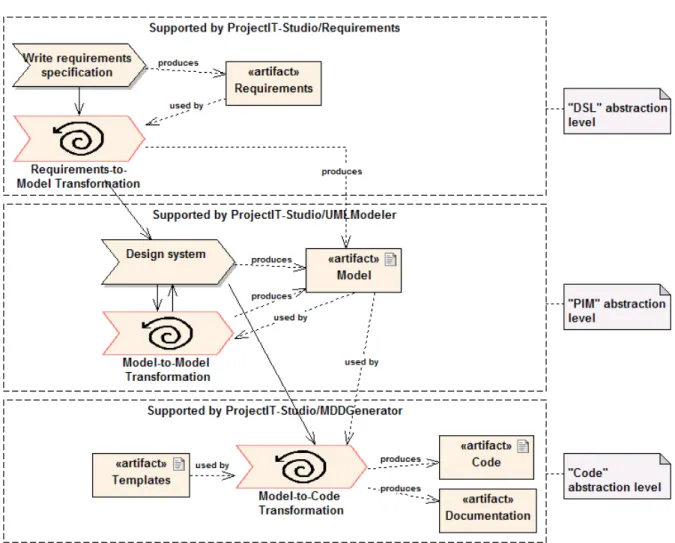
3.6 The ProjectIT approach, supported by the different plugins of ProjectIT-Studio. . . 37
4.1 UML’s multiple-inheritance reflected on a .NET-based language. . . 42
4.2 The packages that compose the UML Superstructure. . . 42
4.3 RootNodes and Views in Enterprise Architect. . . 43
4.4 RootNodeas a container of Packages (its Views). . . 43
4.5 The Profile mechanism in UMLModel. . . 44
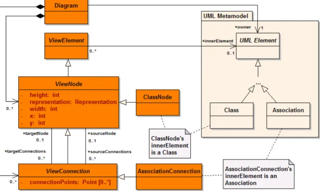
4.6 UML elements are represented by ViewElements in Diagrams. . . 46
4.7 A ViewConnection can be connected to other ViewConnections. . . 47
4.8 The structure of the Serialization package. . . 49
4.9 The relationship betweenModelContents and all model information. . . . 51
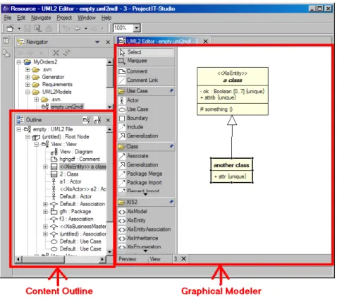
4.10 Screenshot of UMLModeler, highlighting its main packages. . . 52
4.11 The packages of UMLModeler’s functional architecture. . . 53
4.12 Screenshot of the Outline Page provided by UMLModeler. . . 53
4.13 The classes that provide Content Outline functionality. . . 54
4.14 The functional architecture of the Graphical Modeler. . . 56
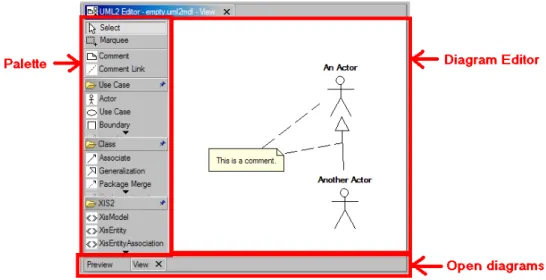
4.15 Screenshot of the Graphical Modeler, highlighting its main visual compo-nents. . . 56
4.16 Overview of the classes of the EditParts package. . . 58
4.17 Class instances involved in a connection between a Comment and a Class. . 59
4.18 Overview of the classes of the Figures package. . . 59
4.19 Overview of the classes that provide palette-related functionality. . . 61
4.20 Examples of the palette, with palette drawers and palette tools. . . 61
4.21 Screenshot of Graphical Modeler’s context menu. . . 62
4.22 Overview of the classes of the Actions package. . . 63
4.23 Overview of the classes of the Commands package. . . 65
4.24 Screenshot of a Property Form for an UML Class. . . 66
4.25 The classes that support the Property Forms mechanism. . . 66
4.26 The components of a Property Form. . . 67
4.27 A tab, with a list of Attributes, in a Property Form of an UML Class. . . . 68
4.28 The ”Applied Stereotypes” tab (top) and a StereotypeApplication’s Property Form (bottom). . . 69
4.29 Screenshot of the Preferences dialog with ProjectIT-Studio’s preference pages. 70 4.30 The structure of the Preferences package. . . 71
LIST OF FIGURES xv
4.32 The structure of the Wizards package. . . 72
4.33 Screenshot of the NewUMLModelWizard and the outline of the resulting model file. . . 72
4.34 List of actions obtained through the ”UMLModelProvider” extension point. 74 4.35 The classes involved in UMLModeler’s transformation mechanism. . . 76
5.1 The multi-view organization of XIS2 (extracted from [Silva 07]). . . 82
5.2 The ”dummy” and ”smart” design approaches defined by XIS2 (extracted from [Silva 07]). . . 84
5.3 The tree structure of the ProfilePackages corresponding to XIS2 views. . 85
5.4 The Stereotypes of the XIS2 Domain View defined in UMLModeler. . . . 86
5.5 Screenshot of the ”Choose Profiles to apply” window. . . 87
5.6 Screenshot of the ”MyOrders2” Actors View with the XIS2 profile. . . 88
5.7 Screenshot of the ”MyOrders2” Domain View with the XIS2 profile. . . 88
A.1 Domain model of MyOrders. . . 113
A.2 NavigationSpace View of MyOrders2. . . 114
A.3 Main interaction space. . . 114
A.4 Main interaction space mappings. . . 115
A.5 Suppliers interaction space. . . 115
A.6 Suppliers interaction space mappings. . . 116
A.7 OrderDetail interaction space. . . 116
A.8 OrderDetail interaction space mappings. . . 117
A.9 Deployment diagrams of the generated application, for Windows Forms (left) and for ASP.NET (right). . . 118
A.10 Component diagram of the generated application. . . 118
A.11 Main screen (Windows Forms). . . 119
A.12 Main screen (ASP.NET). . . 119
A.13 Customers listing screen (Windows Forms). . . 120
A.14 Customers listing screen (ASP.NET). . . 120
A.15 Customer editing screen (Windows Forms). . . 121
List of Tables
2.1 Comparison between the UML tools analyzed. . . 19 6.1 Comparison between UMLModeler and the UML tools previously analyzed. 94
Listings
2.1 Example of an operation expressed in OCL (extracted from [OMG 05b]). . 11 4.1 An extension to ”UMLModelProvider” that provides a transformation. . . 75 4.2 Part of the ModelTransformationInvokerAction’s source code. . . 77 4.3 Example of a validation method. . . 78 4.4 Example of a transformation method. . . 78 5.1 Overview of the source-code that implements the XIS2 ”smart” approach
transformation. . . 89
Chapter 1
Introduction
The development of software information systems is a very complex activity, involving non-trivial issues in various areas such as technology and human resources. Despite the efforts made to overcome the issues related with this activity, these issues are still frequently found in software development projects, with its negative consequent aspects in terms of project scope, time, budget and quality. One of the main causes for this situation is the fact that many projects do not follow a structured, standard and systematic approach, like the methodologies and best practices proposed by the Software Engineering community [Silva 01].
Facing this situation, the Information Systems Group of INESC-ID [INESC-ID] started an initiative in the area of requirements engineering, project management, and model-driven development, namedProjectIT [Silva 04]. This initiative’s main goal is to mini-mize the negative consequences mentioned above, by researching new approaches to accel-erate the underlying development process by automating its repetitive activities (which are error-prone and introduce unnecessary complexity in the final product) thus glob-ally improving the quality of the development process. These new approaches are be-ing implemented in two prototypes (illustrated in Figure 1.1): ProjectIT-Studio and
ProjectIT-Enterprise. The idea of these prototypes is to provide a CASE
(Computer-Assisted Software Engineering) tool, which should keep in mind Software Engineering’s best practices and simultaneously be methodology-independent. Figure 1.2 presents the components of ProjectIT’s functional architecture.
So far, the main results of this project are: (1) a new requirements specification language, called ProjectIT-RSL [Videira 05]; (2) an Unified Modeling Language (UML) [OMG 05b] profile called ”eXtreme modeling Interactive Systems” (XIS), which was proposed and validated in previous work [Silva 03a, Silva 03b] and is currently in its second version; and (3) a set of integrated tools, called ProjectIT-Studio [Saraiva 05a, Saraiva 05b, Silva 06a, Ferreira 06, Silva 06b], that covers the activities of the entire
Figure 1.1: ProjectIT applicational architecture (extracted from [Silva 05b]).
Figure 1.2: ProjectIT functional architecture (extracted from [Silva 06a]).
ware development life cycle, from requirements specification to the generation of artifacts (such as source code and documentation) through the application of generative program-ming techniques.
Interactive systems are a sub-class of information systems that provide a large num-ber of common features and functionalities, such as user-interfaces to drive the human-machine interaction, databases to keep information consistent, and role-based user and
3
access control management [Silva 07]. ProjectIT promotes a platform-independent ap-proach, based on Model-Driven Architecture (MDA) [MDA], for designing interactive systems: (1) specify and validate requirements by using ProjectIT-RSL; (2) obtain a high-level UML model corresponding to the specified requirements; (3) refine the ob-tained model by using the XIS profile, which allows the design of interactive systems at a PIM (”Platform-Independent Model”) level, according to MDA terminology; and finally (4) generate artifacts by using model-to-code transformations specific to different deploy-ment platforms, such as Web, desktop or mobile specific platforms. Figure 1.3 illustrates
the ProjectIT approach with the concrete application of the ProjectIT-RSL language
and the XIS profile.
Figure 1.3: Roles and processes involved in the ProjectIT approach’s workflow (extracted from [Silva 06a]).
The ProjectIT approach is language-independent, which means the Designer is free to choose any UML profile that is considered appropriate to design the system. However, in the current research, using the XIS profile is recommended.
1.1
Motivation
As suggested in Figure 1.3, UML model design is considered a fundamental principle of the ProjectIT approach. This requires that ProjectIT-Studio provide an UML modeling plugin which not only accelerates the traditional task of completely modeling a system, but also features a high level of integration with other ProjectIT-Studio plugins, such as the ProjectIT-Studio/Requirements [Ferreira 06] and the ProjectIT-Studio/MDDGenerator [Silva 06b].
Besides this integration, the plugin must also provide an efficient extensibility mecha-nism. Considering that the ProjectIT approach is language-independent, the plugin must allow the Architect to specify the semantics that are inherent to a specific UML profile. Additionally, the plugin must also allow the specification of possible model transforma-tions, which are a key factor of the ProjectIT approach.
This work describes the creation of ProjectIT-Studio/UMLModeler, a modeling plugin for ProjectIt-Studio that fulfills these requirements and is primarily focused on making the user look upon the ProjectIT approach as an easy and efficient way to model interactive systems.
1.2
Context
This work takes place in the context of ProjectIT-MDD, which is ProjectIT’s func-tional component related to the area of information systems’ modeling and Model-Driven Engineering (MDE) [Schmidt 06]. This component allows the specification of models, transformations between models defined in different languages, and the automatic gen-eration of artifacts (such as source-code and documentation). Figure 1.4 presents a high-level overview of this component’s architecture; the shaded packages indicate the sub-components of ProjectIT-MDD which were developed in the context of this work.
This work was developed in the context of the Information Systems Group of INESC-ID, in strict collaboration with the rest of the ProjectIT-Studio development team, and was supervised by PhD Alberto Manuel Rodrigues da Silva.
1.3. Objectives 5
Figure 1.4: ProjectIT-MDD’s architecture (extracted from [Silva 06a]).
1.3
Objectives
The main objectives of this work are: (1) the development of a graphical modeling plugin for ProjectIT-Studio, called ProjectIT-Studio/UMLModeler, that provides features typical of traditional UML modeling tools; (2) the complete integration of this plugin with the other plugins of ProjectIT-Studio; (3) the support of the UML Profile mechanism, in an elegant and powerful way; (4) the development of a mechanism that constantly monitors the syntactic and semantic consistency of a model, according to the profiles applied to it; and (5) the development of a mechanism that allows the application of user-defined model-to-model transformations.
From the user’s perspective, the modeling plugin should facilitate the realization of the most common tasks in the ProjectIT approach (such as stereotype application and tagged-value edition), so that the user can model systems in a quick and easy way.
This work was validated with several case studies, featuring various levels of com-plexity. This validation was conducted by performing the following steps: (1) define the requirements for the desired system (using ProjectIT-Studio/Requirements); (2) model the system using ProjectIT-Studio/UMLModeler; and finally (3) generate the implemen-tation of the system using ProjectIT-Studio/MDDGenerator.
It is expected that the results of this work will allow ProjectIT-Studio users to eas-ily adopt and follow the ProjectIT approach, by being able to quickly create visual models of information systems and then supply these models as input to ProjectIT-Studio/MDDGenerator, as is suggested in Figure 1.3.
1.4
Document Outline
This MSc dissertation is organized around seven chapters and three appendices, whose contents are described in the next paragraphs.
Chapter 1 – Introduction. This chapter provides a brief overview of the
Pro-jectIT research program, the ProPro-jectIT approach and the prototype tool that supports it: ProjectIT-Studio. Moreover, the context and main objectives of this thesis are also described.
Chapter 2 – State of the Art. This chapter describes the concepts, techniques,
tools, and frameworks that were analyzed in the context of this work. This analysis is particularly centered around: (1) MDE, (2) existing UML modeling tools and their features, and (3) technological frameworks that were either used in this work, or provided some fundamental ideas about what would be the most important factors to consider during the development of ProjectIT-Studio/UMLModeler.
Chapter 3 – ProjectIT-Studio Context. This chapter presents ProjectIT-Studio
in greater detail, namely its high-level component architecture. Additionally, the various individual plugins that constitute ProjectIT-Studio are also presented, although not in great detail (since they were developed in parallel with this work).
Chapter 4 – The UML Modeling Plugin in ProjectIT-Studio. This chapter
presents a thorough description of the ProjectIT-Studio/UMLModeler modeling plugin. The various internal components of the plugin are presented, as well as the technological and architectural decisions that were taken during the course of its development.
Chapter 5 – Supporting the XIS2 UML Profile. This chapter describes how
the XIS2 profile was defined in ProjectIT-Studio/UMLModeler, as a way to validate the plugin as an effective way to specify and apply UML profiles.
Chapter 6 – Conclusions and Future Work. The conclusions drawn from all the
developed work are presented, as well as the future work that should be performed in order to significantly enhance its performance and its user-interaction experience.
Bibliography. Lists the bibliographical references that were found relevant either for research purposes or for the development of the modeling plugin itself.
1.5. Conventions Used 7
Glossary. This appendix presents some keywords mentioned in this document (such
as acronyms and technical terms), describing their meaning.
Appendix A – The ”MyOrders2” Case Study. This appendix presents one
of the most complex case studies that was used in the validation of ProjectIT-Studio’s plugins, and the results achieved.
Appendix B – ProjectIT-Studio Designer’s Manual. This appendix consists of
an in-depth guide describing how to use ProjectIT-Studio/UMLModeler. All the features offered by the plugin are also explained in detail.
Appendix C – ProjectIT-Studio Programmer’s Manual. This appendix
de-scribes the internal mechanisms of ProjectIT-Studio/UMLModeler, and how developers can add new features to this plugin.
1.5
Conventions Used
This thesis is written using the following conventions: (1) the bold face font is used to highlight important concepts, tools and technology that are being presented for the first time in this thesis; (2) theitalic font is used to emphasize a segment of text; (3) thetype writerfont is used for programming language keywords or code segments (e.g., names of classes, attributes, methods, or namespaces) developed or used in this work; and (4) any text enclosed in quotation marks (”) and followed by a reference means that the text was extracted from the referenced document.
Whenever a figure is extracted or adapted from another document, the figure’s caption will explicitly indicate this fact and make a reference to the corresponding document. All the original figures created for this thesis (i.e., not extracted or adapted from some external source) have no such reference. When suitable, figures will consist of diagrams specified using the UML language.
Chapter 2
State of the Art
This chapter presents the concepts, tools, and supporting technologies that are relevant to the work of this thesis. It is divided in three sections: (1) a presentation of the Model-Driven Engineering (MDE) paradigm and some current MDE-related standards, such as the Unified Modeling Language (UML); (2) a comparative analysis of some popular UML modeling tools; and (3) a presentation of the technological frameworks considered important for the implementation of ProjectIT-Studio/UMLModeler.
2.1
Model-Driven Engineering (MDE)
Model-Driven Engineering (MDE) is an emerging technique based on the
system-atic use of models as first-class entities during the solution specification [ModelWare, Schmidt 06]. The MDE paradigm treats the software development process as a set of transformations between models, from requirements to deployment, passing by analysis, design, and implementation. The idea behind MDE is that the real-world problem can be represented by a set of models that capture the essence of the solution’s expected behavior. Unlike previous software development paradigms based on source code as a first-class entity, in this approach models become the first-class entities; source code, doc-umentation, and other development artifacts can then be obtained from those models (much like compilers, which translate high-level language programs into their equivalent machine-language implementations).
There are already multiple initiatives, languages and approaches related to MDE, such as the Unified Modeling Language (UML) [UML], the MetaObject Facility (MOF) [MOF], the Model-Driven Architecture (MDA) [MDA] or the Domain-Specific Modeling (DSM) [DSMForum, Kelly 05]. Usually, MDE approaches are a combination of the usage of certain languages and a method for obtaining artifacts (source code and documentation) from models specified by using those languages. The main difference between the existing
MDE approaches is the offered software development life-cycle stages’ coverage and how each of these stages are handled by the approach (e.g., if the models obtained during that stage are used for code generation, or transformed into other models).
The Object Management Group (OMG) [OMG] is a consortium that produces and promotes computer industry specifications. Originally aimed at setting standards for distributed object-oriented systems, it is now focused on modeling (of programs, systems, and business processes) and model-based standards. The OMG is responsible for some well-known modeling-related standards, such as the Unified Modeling Language (UML) [UML], the MetaObject Facility (MOF), the XML Metadata Interchange (XMI) [XMI] format, and the Query/Views/Transformations (QVT) [OMG 05a]. OMG also created its own approach to MDE, the Model-Driven Architecture (MDA) [MDA], which is based on UML, MOF, XMI, and QVT.
The MDE approach followed by the ProjectIT-MDD component is primarily based on the UML 2.0 and the MDA standards, which are presented in the following subsections.
2.1.1
Unified Modeling Language (UML) 2.0
The Unified Modeling Language (UML) [UML] is a general-purpose modeling
lan-guage, originally designed to specify, visualize, construct, and document information sys-tems. Nevertheless, it is not restricted to modeling software, being commonly used for business process modeling or representing organizational structures, for example.
UML was fundamental in the beginning of MDE, as it established consensus on the various graphical shapes used to represent concepts like classes, inheritance, states, etc. This was the first step in establishing a ”universal” software modeling language, thus allowing developers to effectively transmit their own ideas using a standard notation. UML 2.0 represented a significant leap over its previous version, UML 1.5; although the most significant changes are about the language’s internal architecture (i.e., the way how the UML 2.0 metamodel is defined), there were also changes that affect users, such as new diagram types (UML 2.0 has 13 diagram types versus the 9 diagram types of previous versions), new concepts and notations [Silva 05a, OMG 05b].
The UML 2.0 standard is organized into four different parts [France 06]: (1) the Infrastructure [OMG 06c], which provides the basic modeling constructs used by both UML 2.0 and the MetaObject Facility (MOF) 2.0, which is the metamodel used to spec-ify UML; (2) the Superstructure [OMG 05b], which is the UML metamodel itself; (3) the Object Constraint Language (OCL) [OMG 06a], which provides a language for specifying queries, constraints, and additional operations in UML models (the ”additional opera-tions” specified in the UML Superstructure specification are written in OCL, as Listing
2.1. Model-Driven Engineering (MDE) 11
2.1 illustrates), although these operations do not change the state of the model; and (4) the Diagram Interchange (DI) [OMG 06b], which is an extension to the UML metamodel that supports the exchange of UML diagram layouts for interoperability between UML modeling tools. Figure 2.1 illustrates the relationship between the UML Infrastructure, the UML Superstructure (i.e., the UML metamodel) and the MOF.
Listing 2.1: Example of an operation expressed in OCL (extracted from [OMG 05b]).
1 N a m e d E l e m e n t :: a l l N a m e s p a c e s () : S e q u e n c e ( N a m e s p a c e ) ; 2 a l l N a m e s p a c e s = 3 if s e l f . n a m e s p a c e - > i s E m p t y () 4 t h e n S e q u e n c e {} 5 e l s e 6 s e l f . n a m e s p a c e . a l l N a m e s p a c e s () - > p r e p e n d ( s e l f . n a m e s p a c e ) 7 e n d i f
Figure 2.1: Dependencies between UML 2.0 and MOF 2.0 (extracted from [N´obrega 06]). An UML system model consists of three main views: (1) the functional view, which presents the system’s functionality; (2) the static (or structural) view, presenting the system’s structure (entities and relations between them); and (3) the dynamic view, which presents the internal behavior of the system.
UML is traditionally used as a metamodel, i.e., developers create models using the language established by UML. However, the UML Infrastructure Library also defines the UML Profile mechanism, which allows the user to introduce new notations or termi-nologies, providing a way to extend UML metaclasses to adapt them for different pur-poses. Profiles are a collection of Stereotypes, Tagged Values, and Constraints [OMG 06c, Silva 05a]. A Stereotype defines additional properties for UML elements, but these proper-ties must not contradict the properproper-ties that are already associated with the UML element. Thus, a Profile can only extend UML by introducing new concepts into the language, but does not allow the user to edit the UML metamodel itself.
Although UML was definitely a step forward in setting a standard accepted and easily understood by the whole Software Engineering community and aligning it towards the
MDE paradigm, UML is still criticized for several reasons [Sellers 05, Thomas 04], such as: (1) being easy to use for software-specific domains (such as IT or telecom-style systems) but not for other substantially different domains, such as biology or finance; (2) not being oriented to how it would be used in practice; or (3) its development process being much more driven by politics than by software engineering needs. Nevertheless, it is important to note that UML is often the target of overzealous promotion which raises user expectations to an unattainable level, and the criticisms that follow afterward are usually influenced by this aspect [France 06].
2.1.2
XML Metadata Interchange (XMI)
XML Metadata Interchange (XMI) [XMI] is an OMG standard for exchanging,
defining, interchanging, and manipulating metadata information by using the eXtensible Markup Language (XML) [XML a], and it can be used for any metadata whose metamodel can be specified in MOF. XMI is most commonly used as a format to exchange UML models between tools, although it can also be used for serializing models that are instances of other MOF-based metamodels. Therefore, XMI provides a way to map MOF to XML, which allows the mapping of any MOF-based metamodels – such as UML – to XML, providing an easy and very portable way to serialize and exchange models between tools. Nevertheless, users often regard XMI as a last resort for exchanging models between tools. This is because it is very common for each tool to use its own vendor-specific ”XMI extensions”, which means that there is usually information lost during the process of exchanging models between different vendor tools.
2.1.3
Model-Driven Architecture (MDA)
The Model-Driven Architecture (MDA) [MDA] is a framework for the software
development life cycle, and its main characteristic is the importance of models in the development process; the development process is driven by the activity of modeling the software system [Kleppe 03]. It is based on other OMG standards such as UML, MOF, Query/Views/Transformations (QVT) [OMG 05a] (which deals with model-to-model transformations), and XMI.
The core foundations of MDA consist of the following three ideas [Booch 04]: (1)direct representation, in which the focus of development should shift from the implementation technology to the problem itself; (2) automation, because it makes no sense to manually execute tasks that could easily be performed by automatic means; and (3)open standards, as they help eliminate gratuitous diversity.
2.1. Model-Driven Engineering (MDE) 13
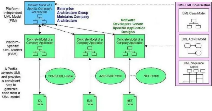
Ideally, MDA generators should be able to build full applications from input models. One of the important concepts in MDA is the idea of multiple levels of models, and MDA defines two types of models: (1) thePlatform-Independent Model (PIM)and (2) the
Platform-Specific Model (PSM) [MDA, Kleppe 03]. A PIM is a model with a high
level of abstraction that makes it independent of any implementation technology. This makes the PIM suitable to describe a software system that supports a certain business; the system is specified from the perspective of how it should support the business, without paying attention to implementation details (like specific relational databases or application servers). A PSM also specifies the system, but in terms of the implementation technology; it is easy to see that, given a PSM, only a developer who has knowledge about the platform corresponding to the PSM will be able to interpret that PSM correctly. A PIM can be transformed into one or more PSMs, each of those PSMs being designed for a specific technology; this is because it is very common for software systems today to make use of several technologies, so developers will be interested in obtaining a PSM per technology from a PIM (which is usually given to them by business experts).
Figure 2.2 presents an overview of MDA, with the concepts of PIM and PSM. The solid lines connecting the boxes are transformations, which are defined by transformation rules. MDA prescribes the existence of transformation rules, but it’s up to the model designer to define what those rules are. In some cases the vendor provides rules as part of a standard set of models, profiles and transformation rules.
2.2
UML Modeling Tools
This section presents some popular UML modeling tools: (1) ArgoUML [ArgoUML]; (2) Enterprise Architect [SparxSystems], from Sparx Systems; (3) Poseidon for UML [Gentleware], from Gentleware; and (4) Rational Rose [IBM], from IBM Rational. Al-though there are many other UML modeling tools currently available, this thesis presents this set of tools because their features and user-interfaces constitute a good representation of the current state of the art of this type of tools.
The analysis of these UML tools focuses on aspects such as: (1) adherence to standards; (2) ease of use; and (3) the set of available functionalities. Finally, a comparison between these tools is presented.
2.2.1
ArgoUML
ArgoUML0.22 [ArgoUML] is an open-source UML modeling tool written totally in Java
and released under the BSD license. Currently, this tool only supports UML 1.4, but its developers consider UML 2.0 as a goal to achieve. Although ArgoUML does not offer many of the functionalities that are typical of UML modeling tools, the tool is worth mentioning since it differentiates itself from the other tools of this kind due to its use of ”cognitive psychology” [ArgoUML] to detect model inconsistencies and promote modeling best-practices. Figure 2.3 shows a screenshot of ArgoUML.
2.2. UML Modeling Tools 15
ArgoUML supports the import/export to XMI, because its models are stored natively in that format. However, due to the fact that XMI started including information about the graphical representation of models only since UML 2.0, ArgoUML stores that graphical information separately from the model. Another interesting feature of ArgoUML is that it enforces user-defined OCL constraints, although this only happens for Classes and Features, because OCL versions before OCL 2.0 considered only these two concepts as allowable contexts to which constraints could be applied [ArgoUML].
This tool also offers code generation capabilities, but it does not provide any model transformations to support the various model abstraction levels of MDA.
2.2.2
Enterprise Architect
Enterprise Architect (EA) 6.1 [SparxSystems], from Sparx Systems, is a commercial
tool that features good usability and a minimal learning curve. EA supports most of the UML 2.0, and is currently known through the Software Engineering community as one of the most versatile UML modeling tools available, offering a wide range of functionalities (such as Model Patterns) that considerably accelerate modeling tasks.
EA provides support for the UML Profile mechanism, and it makes the definition of an UML profile an intuitive task. However, the possibilities of UML profile definition are limited to specifying the generic syntax of the profile (e.g., defining stereotypes and what metaclasses they extend, or enumerations). Other semantic and syntactic relations, and constraints entered in the profile definition (using a text-based notation such as OCL), are not enforced when the user creates a model using that profile; the only validation that EA does enforce is the application of a stereotype to an instance of a metaclass (e.g., a stereotype that extends the metaclass Association cannot be applied to an instance of the metaclassClass). Figure 2.4 shows a screenshot of EA with an example of stereotype definition.
EA supports the import/export to XMI, and diagrams can be exchanged between different instances of EA, although the diagram exchange is done through an EA-specific mechanism (which means that diagrams cannot be totally exchanged between EA and other third-party tools, such as Rational Rose).
EA also offers code generation capabilities and some basic MDA-oriented model trans-formations, such as PIM-to-PSM. However, this tool does not allow users to define their own model transformations.
Figure 2.4: A screenshot of ”Enterprise Architect”.
2.2.3
Poseidon for UML
Poseidon for UML4.0 [Gentleware], by Gentleware, is a commercial UML modeling tool
that is based on ArgoUML. Unlike ArgoUML, this tool supports the UML 2.0, although this support is not yet complete. Additionally, this tool also features a wide range of functionalities, as is expected from a commercial tool. Figure 2.5 presents a screenshot of Poseidon for UML.
2.2. UML Modeling Tools 17
Poseidon supports the import/export to XMI, because its models are stored in this format. However, the diagrams are also stored in XMI, because Poseidon supports UML 2.0 and the Diagram Interchange specification [OMG 06b]; this is unlike what happens with ArgoUML, which stores diagrams separate from the model. Additionally, Poseidon allows users to specify model constraints using OCL 2.0, but those constraints are not enforced by the tool (unlike ArgoUML).
Like ArgoUML, this tool also offers code generation capabilities, but it does not provide any model transformations to support the various model abstraction levels of MDA.
2.2.4
Rational Rose
Rational Rose 2003 [IBM], from IBM Rational, is a commercial UML modeling tool
that is well known in the Software Engineering community. This tool supports the UML 1.x but not the UML 2.0, because the latter was only released in 2005 (two years after the release of Rational Rose 2003). Rational Rose also features a wide range of functionalities that promote modeling good-practices and accelerate the modeling tasks. Figure 2.6 shows a screenshot of Rational Rose.
Figure 2.6: A screenshot of ”Rational Rose”.
Although Rational Rose includes the UML’s standard stereotypes, it does not provide an easy way to add user-defined stereotypes, and there is no support for the definition of a profile. To add a stereotype, the user must use the configuration, scripting and menu-editing facilities of the tool, which is an error-prone process, as it also involves the manual editing of an INI file.
Rational Rose does not natively support the import/export of models to XMI, although there is a plugin by UniSys that adds this functionality to the tool. This same plugin
also allows the import/export of diagrams to XMI, although the generated XMI uses plugin-specific tags to represent diagrams.
This tool also offers code generation capabilities, but it does not provide any model transformations to support the various model abstraction levels of MDA.
It should be noted that Rational Rose has recently been replaced by Rational Soft-ware Modeler [Mittal 05]. This replacement was made in the scope of IBM’s Rational Software Development Platform, which is a common development environment, based on Eclipse [Eclipse]. This platform is shared by other IBM products (such as the Rational Web Developer, the Rational Application Developer, the Rational Software Architect, the Rational Functional Tester, and the Rational Performance Tester), and allows the integration of all these products.
2.2.5
Comparison Between the Analyzed Tools
After analyzing these tools, it was important to compile a list containing the most inter-esting and important functionalities that the tools provided.
Note that the objective of this comparison is to determine a set of features that ProjectIT-Studio/UMLModeler users would likely find interesting and useful in the con-text of ProjectIT-Studio. Nevertheless, some aspects (e.g., generation of source-code or documentation) that would normally be important in stand-alone tools like the ones pre-sented in this section are not mentioned because ProjectIT-Studio has already defined how they will be handled (as is explained in the next chapter, ”ProjectIT-Studio Context”).
This list consists of the following features:
1. Copy Diagram To Clipboard: allows the user to place screenshots of diagrams in the clipboard, for any kind of purposes;
2. Save Diagram As File (related to the previous feature): allows the user to save screenshots of diagrams in an image file;
3. Create Pattern: allows the capture of certain recurring patterns (like the ones from [Gamma 95]) that the user keeps applying;
4. Create Classes From Patterns (related to the previous feature): allows the applica-tion of patterns to a model;
5. Provides ”Model Overview” Tree: provides a way to quickly get an overview of the model, by presenting it in a tree structure;
2.2. UML Modeling Tools 19
6. Create Diagram Elements From Model Overview Tree (related to the previous fea-ture): allows the user to place an already-existing element into a diagram, by drag-ging it from the Model Overview tree to the diagram;
7. Create Profile: allows the definition of a profile, as a collection of user-defined elements that extend the UML language (i.e., stereotypes);
8. Create Stereotype (sometimes related to the previous feature): allows the definition of a stereotype, as an element that extends the UML language (note that a tool that supports the creation of stereotypes does not necessarily support the creation of profiles);
9. Custom Icons For Stereotypes (related to the previous feature): allow the definition of alternative representations for a stereotype;
10. Supports UML 2.0: this feature is important because UML 2.0 is the standard at the moment;
11. Supports User-Defined Model-to-Model Transformations: allows users to define their own model-to-model transformations, and later apply them to a model;
12. UML Standard Stereotypes: allow users to apply the stereotypes defined in the UML Superstructure specification;
13. XMI Import/Export: allows the achievement of interoperability between different tools;
14. Enforces User-Defined Constraints: allows users to provide their own constraints (into the model, a profile, or a stereotype) and the tool will ensure that the model is consistent with all of those constraints.
Table 2.1 presents an overview of the main features offered by the UML modeling tools analyzed in this section, as well as the support that each tool offers to these features.
Some interesting conclusions can be taken from this analysis: (1) all tools allow the export of a diagram to the clipboard or a file; (2) all tools provide a tree-based ”model explorer”; (3) all tools allow the creation of stereotypes, although only some tools allow alternative icons; (4) it is relatively rare to find a tool that enforces user-defined model constraints; (5) none of the tools allow the specification of user-defined model-to-model transformations; (6) all tools provide a set of the UML’s standard steretypes; and (7) all tools support the import/export to XMI.
Table 2.1: Comparison between the UML tools analyzed.
2.3
Technological Frameworks
This section presents the technological frameworks that are relevant to this work: (1) the Microsoft .NET Framework [.NET a]; (2) the IKVM.NET framework [IKVM.NET]; (3) the Eclipse.NET platform [Eclipse.NET]; (4) the Eclipse Graphical Editing Framework (GEF) [EclipseGEF b]; (5) the nUML project [nUML]; and (6) the Eclipse UML2 project [EclipseUML2].
Although there are other implementations of the UML metamodel, the Eclipse UML2 and nUML projects are the only ones that fulfill the following requirements: (1) support UML 2.0; and (2) their licenses present no objections to being used in ProjectIT-Studio (both projects are open-source and do not have such integration restrictions). Because of this, both projects are thoroughly analyzed in this thesis.
2.3.1
Microsoft .NET Framework (.NET)
The .NET Framework [.NET a, .NET c] is a platform that supports the development
and execution of command-line or form-based applications, web applications, and web services. This platform provides an execution mechanism, called Common Language Runtime (CLR), and a class library to support software development, designated ”.NET Framework Class Library”. The .NET Framework architecture and the relationship
be-2.3. Technological Frameworks 21
tween the CLR and the surrounding operating system and applications are presented in Figure 2.7.
Figure 2.7: The .NET Framework architecture (extracted from [.NET b] and [.NET c]).
The CLR manages the application’s code execution, converting instructions in Mi-crosoft Intermediate Language (MSIL) (the language to which source code is initially compiled) to the corresponding native machine-code instructions in real-time. The CLR is also responsible for core services that provide memory management for processes and threads, as well as offering exception handling, runtime compilation, and reflection mech-anisms that can be enhanced by using remote method invocation functionality, while still assuring a high security and robustness level.
Source code management is crucial to the .NET platform, and that’s the main reason for the existence of managed and unmanaged code concepts. The difference between the two concepts lies on whether code is aimed at the CLR provided environment’s function-ality or not, respectively.
The .NET Framework Class Library is another important component of this platform, as it provides a collection of classes that can be used to develop software applications. These out-of-the-box classes provide typical I/O functionality, string manipulation, com-munication mechanisms, user interface creation, collection management, and other typical programming languages abstractions to ease the developer’s tasks.
With the .NET framework, it is possible to build a wide range of software applications, ranging from simple command line applications or ”fat clients” using Graphical User
Interface (GUI) controls, to complex web applications based on ASP.NET technology [ASP.NET] (using WebForms and XML-based interoperable Web Services).
The .NET Framework is currently in version 2.0, which presents several improvements when compared with the previous 1.1 version [.NET d]. Along with this new version of the .NET Framework came the C# 2.0 language, which presents some new features, such as: (1) generics, which allow the type-safe configuration of collection classes, enabling developers to achieve a higher level of code reuse and enhanced performance when dealing with typical collection classes; (2) partial classes, which are used to split large classes in several files (this can be very useful to separate automatically-generated code from user-defined code, for example); (3) nullable types, which allow a value-type variable to contain a null value; (4) anonymous methods, which supports the lambda calculus (i.e., to pass a block of code without a name as a parameter anywhere a method is expected, instead of defining a new named method); (5) static classes, which provide a safe and convenient way of declaring a class containing static methods that cannot be instantiated; and (6) property accessor accessibility, which allows the definition of different levels of accessibility for the get and set accessors on properties.
In conclusion, the major benefit of the .NET Framework derives from the improved scalability and performance of the applications that can be developed with this plat-form, and from the restructuring of the ASP.NET technology to the new ASP.NET 2.0, which features new types of web controls and a better support for various browsers and computational systems.
2.3.2
IKVM.NET
The IKVM.NET tool [IKVM.NET] is a Java Virtual Machine (JVM) [Java] for the
.NET platform. It appeared in a peculiar context and time when most of the software community believed that Java and .NET technologies were mutually exclusive. The goal of IKVM.NET is to reduce the gap between these two technological platforms by providing an interoperability mechanism to overcome this pitfall. It mainly offers a variety of integration patterns between the Java and .NET languages and platforms, by applying virtual-machine-related technologies for byte-code translation and verification, and class loading. Figure 2.8 illustrates how this tool works and how it achieves interoperability between the two platforms.
This tool has two operation modes: (1) static mode, in which Java byte-code is previ-ously translated to MSIL and compiled into a .NET assembly that can be used by .NET applications (thus providing a mechanism for using objects defined in the Java platform as if they were .NET objects); and (2) dynamic mode, in which Java classes and JAR files are
2.3. Technological Frameworks 23
Figure 2.8: How IKVM.NET achieves interoperability between Java and .NET. directly used, without any previous conversion, to execute Java applications on the .NET runtime environment (Java byte-code is translated to MSIL instructions in runtime).
The IKVM.NET tool is composed by three applications: (1) ikvm, which supports the dynamic mode; (2)ikvmc, which supports the static mode; and (3)ikvmstub, which is required to create .NET stubs from .NET assemblies, thus allowing Java code to be compiled by referencing .NET code.
The ikvmstub application is a tool to generate JAR files that act as stubs (or ”empty representations”) of .NET assemblies, so that Java code can be compiled by referencing .NET code. This feature is very useful since it allows Java code to use .NET function-ality, by just referencing the ”empty” classes available in the stub JAR file. The other IKVM.NET applications then detect API calls to the stubs and replace them with invo-cations to the ”real” .NET functionality.
Theikvm application is a starter executable used in dynamic mode to play the role of the JVM (i.e., it allows the execution of a Java program on the .NET framework without any previous transformation of the Java classes). This functionality is achieved by on-the-fly conversion of Java’s API calls to .NET API calls at runtime. This tool also detects API calls to .NET assembly stubs, and replaces those calls with the corresponding calls to the .NET functionalities represented by those stubs.
Theikvmc application is the ”static mode” compiler, used to compile Java classes and JAR files into a .NET assembly (EXE or DLL, depending on whether any of the Java classes provides a ”main” method). Like theikvm application, this tool also detects API calls to .NET assembly stubs, and replaces those calls with the corresponding calls to the .NET functionalities represented by those stubs.
2.3.3
Eclipse.NET
Eclipse.NET [Eclipse.NET] is an open-source project that aims to deliver an
extensi-ble, open platform to support the development of integrated tools for the .NET runtime environment. It is a plugin-based application and framework that eases the process of
building, integrating and using software tools within the .NET execution environment. The default configuration of the Eclipse.NET platform includes a set of plug-ins that ex-tends the platform with some features typically found in an IDE, but it is more than an IDE. It is inspired by the success of the Eclipse project [Eclipse] in delivering a similar platform for the Java execution environment.
Eclipse.NET features a plugin-based architecture that focuses on modularity and plu-gin collaboration, while allowing full control over pluplu-gin dependency relationships (i.e., developers have full control to specify dependencies between the developed plugins). Its main architectural concepts are: (1) the core Platform Runtime, (2) the plugin and (3) the extension point[Saraiva 05a].
The Platform Runtime is responsible for configuring the Platform, detecting available plugins, reading their manifest files, building a plugin registry, and performing some validation tasks, such as detecting extensions to extension points that do not exist. After all these tasks have been completed, the Runtime makes the registry and the Platforms configuration available to plugins.
An Eclipse.NET Plugin is Eclipse.NET’s smallest unit of behavior. Any tool can be developed as a plugin or as a set of plugins. In fact, all of the Platform’s functionality is located in plugins, the exception to this being the functionality in the core Platform Runtime. A plugin also features a manifest file which contains information about the plugin itself, such as extension points (explained below) that the plugin provides, and what extensions the plugin provides to extension points defined by other plugins. This manifest file is located separately from the plugin itself, because Eclipse.NET’s plugin-loading mechanism uses theLazy Load design pattern [Fowler 03], so the Runtime can read the information about the plugin without actually loading the plugin into memory. This way, the Runtime can build the registry without loading every plugin, thus saving resources. Plugins can also depend on each other. These dependencies are expressed in the plugin’s manifest file. This way, a plugin will only be used (and, of course, successfully loaded) if all other plugins on which it depends are also successfully loaded.
AnEclipse.NET Extension Point is a way for plugins to inter-operate with each other. This interconnection model is achieved through the classical process: (1) any plugin can declare any number of extension points; (2) on the other hand, any plugin can provide any number of extensions for one or more extension points declared by other plugins. Figure 2.9 illustrates how plugins and extension points are related. Plugin 1 declares three extension points (Extension Point 1, Extension Point 2, and Extension Point 3). Extension Point 1 and Extension Point 2 receive the extension (or contribution) from Plugin 2. On the other hand, Plugin 2 also declares two other extension points (Extension Point 4 and Extension Point 5). These last two extension points may also receive contributions from
2.3. Technological Frameworks 25
other existing plugins. Plugin 1 may also be contributing to other existing extension points, not represented in the figure.
Figure 2.9: Plugins can declare, and contribute to, extension points (extracted from [Saraiva 05a]).
Eclipse.NET was created in a previous work [Saraiva 05b] with the main purpose of being an integration platform on which ProjectIT-Studio (as well as any other platforms) could be based [Saraiva 05a].
As in the Eclipse project, Eclipse.NET’s graphical environment is still based on the
Standard Widget Toolkit (SWT) [EclipseSWT]. SWT is a platform-specific
run-time that offers widget objects (such as text boxes, scroll-bars, and other familiar user-interface controls) to Java developers, but underneath uses native code calls to create and interact with those controls, making SWT-based applications essentially indistinguishable from native platform applications.
The tree of SWT widgets is primarily based on the Composite design pattern
[Gamma 95, Gamma 03], whose structure is illustrated in Figure 2.10; this pattern is applied to SWT by defining a special type of widget, calledComposite, which can contain other widgets; this means that SWT allows a developer to create user-interfaces with a varying degree of complexity by simply creating a tree of SWT widget instances. Examples of composite widgets include the traditionalTreeorList widgets. Figure 2.11 illustrates how this design pattern is applied to SWT.
2.3.4
Eclipse Graphical Editing Framework (GEF)
The Eclipse Graphical Editing Framework (GEF)) [EclipseGEF b, EclipseGEF a]
Figure 2.10: The Composite design pattern’s structure (extracted from [Gamma 95]).
Figure 2.11: The Composite design pattern applied to SWT (extracted from [Gamma 03]). environment for plugins on the Eclipse Platform [EclipseGEF b]. GEF allows the devel-oper to create graphical editor plugins based on the Model-View-Controller pattern
[Fowler 03].
The MVC pattern is often used by applications that need to maintain multiple views of the same data (or model). This pattern categorizes objects as one of three types:
(1) Model for maintaining data; (2) View for displaying the data; and (3) Controller
2.3. Technological Frameworks 27
same model can be used with multiple views and controllers, and new types of views and controllers can also use that model without forcing a change in the model design.
GEF consists of two plugins, illustrated in Figure 2.12, for the Eclipse Platform: (1)
theDraw2Dplugin; and (2) theGEFplugin (after which the framework itself is called).
Figure 2.12: The plugins that compose the Graphical Editing Framework (GEF). The Draw2D plugin essentially consists of a lightweight widget system hosted on a SWT Canvas, which is a widget that provides a generic drawing surface that can be used like a traditional drawing board. This plugin provides developers with the ability to graph-ically display anything they want by drawingFigures, which are the graphical building blocks of Draw2D. Developers can use some standard shape figures, such as Ellipse, Polyline, RectangleFigure or Triangle, or create their own figures. Additionally, some figures can act as an overall container for child figures, allowing the construction of relatively complex figures (by using the Composite design pattern). Figure 2.13 presents a tree of figures and the respective representation if each figure is painted as a full rectangle.
Figure 2.13: A tree of Figures and their representation (extracted from [EclipseGEF a]). The GEF plugin, on the other hand, is responsible for implementing the MVC frame-work itself. Although GEF does not provide any mechanism for defining the Model component (thus allowing the developer to use any possible model), GEF does provide mechanisms for defining both the View and the Controller components, as Figure 2.14 illustrates.
The View component is defined by using Draw2D Figures; there is one figure per model object, although that figure can contain other figures (e.g., figures representing fields of the model object). Although it is possible to define a figure by using the corresponding model object (i.e., by allowing the figure constructor to receive the corresponding model
Figure 2.14: GEF is a framework oriented towards the MVC pattern.
object directly), it is generally considered good practice to completely separate the View and Model implementations and leave the mapping between them to the Controller, as this mapping may be non-trivial; otherwise, if this was done in the View, it would likely originate situations in which logic was embedded in the View definition, which is usually not desired.
The Controller component is defined by using EditParts. An EditPart is respon-sible for: (1) linking a model object to its visual representation; (2) making changes to the model, when the proper user input is received; and (3) detecting changes to the model and updating the view accordingly. Most interaction with EditParts is done by using Requests. Requests specify the type of interaction, and are used in various tasks, such as targeting, filtering the selection, graphical feedback, and most importantly, ob-taining Commands (which are the implementation of the Command design pattern
[Gamma 95]). A Command is used to encapsulate an user action as an object, provid-ing the ability to support undoable operations. Figure 2.15 illustrates how Commands are obtained and how they are used: (1) an EditPart is asked for the Command corre-sponding to the given Request; (2) the Command is returned and executed; and (3) the execution of the Command changes the model. Although not represented in Figure 2.15,
2.3. Technological Frameworks 29
the changes made to the model will be detected by the corresponding EditPart, which will then update the view accordingly.
Figure 2.15: Commands are created by EditParts to modify the model (extracted from [EclipseGEF a]).
2.3.5
nUML
nUML [nUML] is a .NET library for manipulating UML 2.0 models, supporting serial-ization to and from XMI 2.1. Like the Eclipse UML2 project, it’s goal is to provide an infrastructure for creating and manipulating UML 2.0 models.
This project is still in its early stages and thus still suffers from a lack of crucial features, such as: (1) the inability to apply a stereotype to an Element (because this mechanism is not clearly described in the UML specification); (2) the UML elements do not support the Observer design pattern [Gamma 95], which would be required to alert any interested parties that the state of an Element has changed; and (3) there is no type-checking on any of the operations available in each Element.
These features are essential to a well-structured modeler, with special relevance to the usage of the Observer pattern. This pattern is very important in the context of model editors (such as the ProjectIT-Studio/UMLModeler tool) because it allows the decoupling of editor logic from model logic (i.e., the editor does not have to know internal details about the behavior of the model). This simplifies the creation of the editor, since it only has to add itself as an ”observer” of the model and interpret events as they appear.
Although the project itself seems promising, the current lack of these features was considered very serious, and it was the reason why it was decided not to use the nUML library in this work.
2.3.6
Eclipse UML2 project
The Eclipse UML2 project aims to provide an UML 2.0 implementation library based
frame-work and code generation facility for building tools (and other applications) based on a structured data model specification.
The purpose of this UML 2.0 implementation is to provide an infrastructure that allows Eclipse plugins (or even other Java applications) to create and manipulate UML models. The Eclipse UML2 project is still in development, with its implementation covering the majority of the UML 2.0 metamodel.
Applications that are not based on Eclipse can also use this library, although they must also use some other Java-based libraries (namely the libraries required by EMF) due to some project dependencies. The size of the UML2 and the EMF libraries themselves is in the order of the megabytes (MB). However, the Java platform does not load library (JAR) files as a whole, but rather only accesses the class files contained in those libraries, and such loading operations occur only when necessary. This means that, in practice, the loading of the UML2 library and its dependencies occurs gradually over time, thus not affecting application performance in a way that is noticeable by the application user.
This library can also be used in the .NET environment, by using the IKVM.NETikvmc
tool for static compilation of such libraries from Java to .NET. Nevertheless, this particular case comes at a relatively heavy cost, as the resulting .NET library is a single file that has a size also in the order of the megabytes; additionally, the .NET Framework loads libraries and their dependencies as a whole (unlike the Java platform, which loads class files when necessary instead of loading entire libraries directly). This means that, when this library is loaded by a .NET application, there will be a significant performance penalty (because the application’s process must allocate a significant amount of memory and the entire library must be loaded into memory) which will be noticed by the application user.
Despite this performance problem in the .NET environment, the Eclipse UML2 library was initially used in this work. However, because of some problems that surfaced during the implementation of ProjectIT-Studio/UMLModeler, it was decided to stop using this library. The rationale for all the decisions regarding Eclipse UML2 in the context of this work are explained in Chapter 4.
Chapter 3
ProjectIT-Studio Context
This chapter presentsProjectIT-Studio, which provides the context for the development of the UML modeling plugin. ProjectIT-Studio is presented from a number of different viewpoints: (1) the usage scenarios that it is meant to support; (2) its component archi-tecture, based on Eclipse.NET plugins; and (3) the kind of support that ProjectIT-Studio offers to MDA.
3.1
ProjectIT-Studio Usage Scenarios
ProjectIT-Studio is meant to support two primary usage scenarios: (1)stand-alone (single-user), and (2) collaborative work (multi-user). Figure 3.1 illustrates these scenarios.
Figure 3.1: ProjectIT-Studio usage scenarios (extracted from [Silva 06a]).
![Figure 1.3: Roles and processes involved in the ProjectIT approach’s workflow (extracted from [Silva 06a]).](https://thumb-us.123doks.com/thumbv2/123dok_us/10167314.2918835/23.892.132.806.491.1068/figure-roles-processes-involved-projectit-approach-workflow-extracted.webp)

![Figure 2.11: The Composite design pattern applied to SWT (extracted from [Gamma 03]).](https://thumb-us.123doks.com/thumbv2/123dok_us/10167314.2918835/46.892.221.629.410.881/figure-composite-design-pattern-applied-swt-extracted-gamma.webp)
![Figure 3.4: ProjectIT-Studio’s plugins and relations between them (extracted from [Silva 06a]).](https://thumb-us.123doks.com/thumbv2/123dok_us/10167314.2918835/55.892.243.703.282.667/figure-projectit-studio-s-plugins-relations-extracted-silva.webp)