A new ion beam analysis data format
N. P. Barradas1,2,* , M. Mayer 3, M. Thompson 4 (1)
Instituto Tecnológico e Nuclear, Estrada Nacional 10, 2686-953 Sacavém, Portugal
(2)
Centro de Física Nuclear da Universidade de Lisboa, Av. Prof. Gama Pinto 2, Lisboa, Portugal
(3)
Max-Planck-Institut für Plasmaphysik, EURATOM Association, Boltzmannstrasse 2, D-85748 Garching, Germany
(4)
Dept. of MS&E/Bard Hall 328, Cornell University, Ithaca, NY 14853, USA
Computational Ion Beam Analysis (IBA) codes such as RUMP, SIMNRA, NDF, and others implement various formats to store the spectral data and to describe the experimental conditions and simulation or fit parameters. Additionally, many laboratories have developed their own internal data formats. These various data formats are isolated applications and generally incompatible. The need for a universal IBA data format (IDF) has been recognised for many years to allow easy transfer of data and simulation parameters between codes, as well as between experimentalists and data analysts. To be effective, the IDF must be transparent (easily read by an IBA practitioner), universal (catering to varying needs), and must include the most common features desired by both experimentalists who collect and archive data and by users who analyse the data. The IDF must also be readily extensible in order to include features specific to individual codes and laboratories, as well as being able to incorporate new features and options in the future. We have developed such a data format. It is currently being implemented in the most popular general purpose IBA data analysis codes. We present here its main features.
Keywords: ion beam analysis; computer codes; data storage PACS: 82.80.Yc; 07.05.Kf
1. Introduction
Data acquisition systems and data analysis codes all implement different formats to represent and store the data, the experimental conditions, any analysis parameters, the description of the sample, and others. Data acquisition systems normally support specific (sometimes proprietary) formats, and experimentalists often convert these to their own favourite formats. RUMP and SIMNRA developed their own data formats to read and write all this information. NDF is user-driven and can read over 30 data formats, but writes specific format files. This is a strong barrier against interchange of data between people from different laboratories, or that use different set-ups to measure their data, different computers to store their data, and different data analysis programs to analyse their data.
We propose and describe a new IBA data format, that aspires to support all forms of IBA data in a well defined simple format permitting easy exchange between sites and analysis programs. Its main characteristics should be: 1) It can be read and understood by inspection of the file, i.e. it is ASCII. This implies it is portable amongst all hardware platforms, and it is self-explanatory 2) It is flexible enough to cater to all IBA data needs, so a file entry can correspond to one given sample, or to a group of similar samples, or to one experimental run, or it may contain simulations only, or anything else that the user may need. 3) It is easily extendable; while the most commonly used features are already included in the new data format, new needs are easy to accommodate. For instance, most data analysis codes use similar layered sample descriptions, but the codes treat roughness or equation overlays in different non-equivalent ways; code-specific extensions to the basic data format are allowed, solving this problem.
In the first meeting of the IAEA Intercomparison of IBA Software exercise [1], that took place in December 2003, it was already recognised the need for a universal IBA data format (IDF), and also that XML [2] fulfilled the desired characteristics. A final decision to
establish the IDF was taken when the development of a universal IBA data format became the first milestone of the European Commission-supported SPIRIT [3] Integrated Infrastructure Initiative, which integrates 11 leading European ion beam facilities from six member states and two associated states. A similar approach was taken by the NeXus International Advisory Committee (NIAC), that develops NeXus, an XML-based common data format for neutron, x-ray, and muon science [4]. The possibility of integrating IBA-specific requirements in NeXus was considered, as NeXus is being developed since 1994 by a large group of developers and users and offers many software facilities. This was discarded because NeXus is oriented towards instruments, i.e. experimental facilities, which are notoriously different in IBA and in the neutron and x-ray scattering world; to establish an IBA extension to NeXus, each separate IBA instrument would have to be defined and submitted to the NeXus International Advisory Committee (NIAC) for revision and ratification, which is a process that typically takes years, even not considering that the NIAC holds no IBA expertise.
Here, we describe the main characteristics of the IDF, which is being implemented in RUMP [5], SIMNRA [7,8,9], and NDF [10,11,12].
2. The IBA Data Format definition
The extensible mark-up language (XML) was developed by the World Wide Web Consortium (W3C) to structure, store, and transport data. Although often associated with the internet, XML is by no means a specific internet language, and there are many non-internet XML applications.
In particular, XML has no pre-defined tags (keywords to carry specific information). In fact, the IDF is a definition of all the elements (also called tags) allowed, how they are structured, which information they can contain, and how it can be extended - in short, what is called an XML schema. A given file is an IDF file if it is validated against the IDF schema.
The schema contains no specific information about any experiment; it just defines the structure of the IDF files. In fact, the IDF schema is the definition of the IDF data format.
For instance, we show in Fig. 1a) an IDF file, where most elements are collapsed and their content is not shown. The only elements that are fully expanded are those that define the beam (note that in a complex case, the “beam” group would include definition of foils, slits, charge state distribution, and others). We show in Fig. 1b) the part of the IDF schema that defines the element “spectrum”, which normally will contain all the experimental conditions as well as the spectrum as such, and also any data processing made, such as a fitted curve together with any scattering cross sections or stopping powers used in the calculation (and will not contain information about the sample structure, reserved for the element “structure” defined elsewhere). This element “spectrum” structures the relevant information in daughter (lower-level) elements such as "beam", "geometry", "data", or “process”. Each one of these is defined elsewhere in the schema, and contains further elements in a structured well-defined way. Note that not all tags defined in the schema are in the IDF file, and conversely, there may be user-specific tags in the IDF file that are not explicitly included in the IDF schema, but are included instead in a different, user-defined, schema.
With this example in mind, the general philosophy of IDF is:
- The basic elements of IDF are data groups and data items. Data items are e.g. “layerthickness”, or “concentration”; these data items can be real numbers, integer, or even text (e.g. “geometrytype” can be “IBM”, “Cornell”, or “general”). Data groups are logically organised (e.g. “geometry”, “stoppingpowers”, or “structure”), and can contain other data groups as well as data items.
- The information is structured as a tree. Each data group is a node of the tree. Standard tree parsing methods can be applied.
- The elements appear, inside the group to which they belong, in fixed order that must be respected. These pre-defined elements support most, but not all, IBA needs, with RBS, ERDA, non-resonant NRA, resonant NRA (including NRP and PIGE), and PIXE being explicitly supported. However, all elements are optional, they need not appear. The apparent complexity of the data groups does not in fact exist in normal cases and simple experiments.
- Each data group can start with the elements “users” and “notes”. The group “users” should be for information on e.g. sample owner, experimentalist, data analyst. The group "notes" is an all-purpose way of including any comments and remarks.
- Any number of non-IDF elements can be inserted in any data group, at the end. They are clearly identified with a prefix, that is unique to each specific code or user that wishes to have their own elements. For instance, all NDF specific tags will be identified with the prefix “ndf:”. This makes the IDF fully flexible and extensible. The prefix must be assigned to a schema developed by the code or user in question.
- All elements that describe a quantity have as mandatory attribute “units” (e.g. “keV”, “nm”, “1e15at/cm2”), as well as optional attributes such as “quantity” (e.g. “energy”, “thickness”, arealdensity”) or “uncertainty” (and even “uncertaintyA” and “uncertaintyB” for types A and B [13], respectively, and “uncertaintyplus” and “uncertaintyminus” for the upper and lower limits, respectively).
- All elements that describe a spread have as optional attribute “mode”, which can be “FWHM”, “sigma”, or “variance”.
- Not all units are allowed, since it would lead to severe parsing problems by software. For each quantity, only certain units are allowed. These are listed in the IDF documentation [14].
The IDF has as top level tags "users", "notes", "attributes" defining things such as the IDF version and file name, “sample”, and "repository". The data group "sample" carries all the information relating to one given sample, including all measurements and analyses, in a clearly organised simple way. In an IDF file, there can be any number of “sample” entries. Each one can contain the following data groups:
The “elementsandmolecules” data group includes the definition of the elements present, and optionally the molecules present (given the molecules, the elemental information is redundant, but not all codes support molecules).
The “structure” data group includes the definition of the sample structure as relevant for most IBA techniques: crystalline symmetry (for channelling techniques), and two complementary ways of defining a depth profile. The first way is a layered structure definition, where the composition is assumed constant in each layer. The second way is the “point by point” profiles calculated e.g. with SQUEAKIE-style codes [15], and often used nowadays in heavy ion ERDA, where for each element a depth/concentration profile is calculated directly from the data. Roughness and profile functions are not supported, as the few codes that support them do it in different ways, and will need to define their own specific tags.
The “spectra” data group can include as many “spectrum” data groups as wished. This supports multiple spectra collected for the same sample, in different conditions and with different techniques. The “spectrum” data group includes the data groups “log” (e.g. for real and live time), “environment” (e.g. temperature and pressure), "beam", "geometry", “instrument”, "detection", “calibrations”, “reactions”, "data", and “process”.
The “beam” group joins all information about the beam before it hits the sample: beam species and energy, beam energy and angular spread, current and fluence, charge state (single or distribution), description of any foils and slits located before the sample, and beam shape.
The “geometry” group defines the geometry type, the angles of incidence, scattering and exit, the detector solid angle, and shape and size of the spot on the sample.
The “instrument” data group briefly describes the ion source, accelerator, beam line, experimental chamber and sample holder.
The “detection” group describes the detection system, including the detector and any slits and foils located between the sample and the detector, as well as the electronics used.
The “calibrations” group contains system calibrations that depend on the detected particle, such as detector efficiency, resolution, or energy calibration. These can be given as pertaining to the whole system or for individual detected particles
The “reactions” group describes the reactions and scattering events that lead to detected particles.
The “data” group contains the data measured. There are many different types of data that can be measured, and it is difficult to find a universal representation. The IDF supports most normal types of data while allowing for a great deal of flexibility. In particular, the data can be included simply by specifying the corresponding file name and type, which is essential in cases where data files are very large (for instance, for position sensitivie or pixelated detectors), and best represented in binary form.
The “process” group contains everything that pertains to data analysis. It includes any number of simulations made, for instance, besides the full simulation of the data, it can include simulation of partial spectra corresponding to a single element, or a given layer. This data group also includes cross sections and stopping powers used, straggling models, and any other data bases used. Input is flexible, it can be made in full, or referring to a given file, or even to a given data base (such as IBANDL [16]) or code (such as SigmaCalc [17] or SRIM [18]). Code-specific tags defining options used to produce the simulations may also be given in this group.
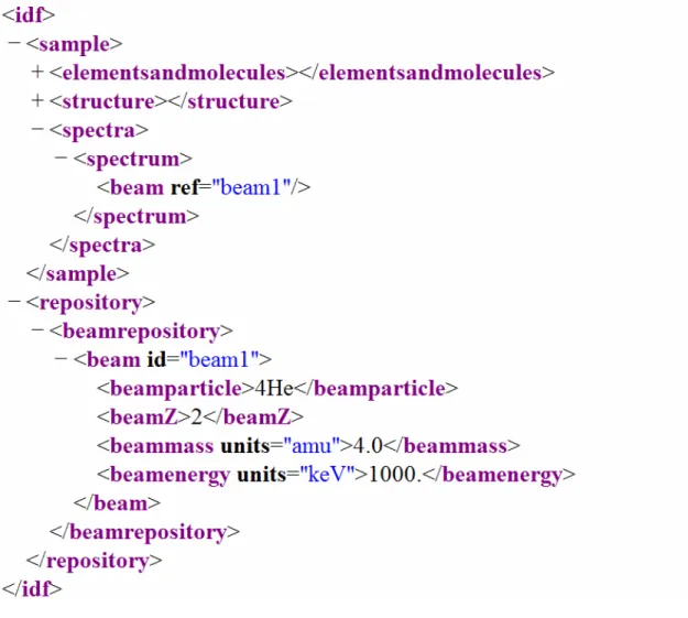
Using only the "sample" data group when for instance many different samples were measured with the same or similar experimental conditions (as in an experimental run), would lead to repeating the same information for each sample. The "repository" data group allows for a more concise way of structuring the information in this case. Within this data group, one can define independently any number of different “beam” groups, that is, different beams that were used, as well as any number of different “elementsandmolecules”, “geometry”, “instrument”, “detection”, and “calibrations” groups. Each group is given a unique identifier, an attribute called “id”. Then, for each sample and spectrum, a reference can be made to the appropriate group via an attribute called “ref” that points to the “id”. In a given sample, both methods are allowed, i.e. , a full definition can be given for some data groups, while referencing a definition given in the repository can be used for other data groups. The only restriction is that if a given data group is defined by referencing, then it can not be partially re-defined, i.e. it can contain only the ref="" attribute, and no child elements. The "repository" data group is illustrated in Fig. 2, with an IDF file equivalent to the one shown in Fig. 1a).
4. Extensibility
In XML, extensibility is provided by the schema, that can allow or forbid elements not defined in the schema to be included in the instance files. In IDF this is allowed, but the new elements must be defined in a separate, user-defined, schema. That is, user-specific tags must be defined in a user-specific schema, which is then referred to in the instance IDF file. This ensures correctness, transparency, and also that different users do not make conflicting specifications.
When an IDF file that uses specific elements is given to a different user, the user-specific schema must be given as well, in order to allow identification of the non-IDF elements. These may then be used or simply ignored.
5. Why should IBA practitioners adopt the IDF
The IDF defines a standard that is independent of machine and of operating system, ensuring readability by future generations of hardware.
As the NeXus Committee stresses [4], a common data format reduces the need for local expertise, the number of conversion utilities, prevents redundant software development, and increases cooperation in software development, amongst other advantages.
Three of the main IBA general purpose codes (RUMP, SIMNRA, and NDF) adopted the IDF, making data interchange between these codes trivial. IDF also allows an easier automatic import of experimental parameters (such as real and life time, pile-up parameters etc.) into simulation codes. These parameters are currently either neglected, or imported by hand. In general, the IDF can be used as an interchange data format between experimentalists and data analysts from different laboratories. In particular, users of these three codes have a strong incentive to use the IDF.
Open source routines that support the IDF are being developed, which will facilitate the simple ability for experimental labs to write data files conforming to the standard
6. Summary
We propose and describe a new IBA data format, called IDF, that aspires to support all forms of IBA data in a well defined simple format. The IDF is based on XML. A stable version 1 of the IDF definition schema is given in the URL associated with the IDF schema,
http://idf.schemas.itn.pt, together with IDF documentation [14], and some examples of IDF files corresponding to calculations of the IAEA intercomparison of IBA software exercise [1].
NPB would like to thank the European Union for support under the SPIRIT consortium. The first steps leading to the IDF were made in the International Atomic Energy Agency intercomparison of IBA software framework. Dr. Miguel Reis contributed extensively to the definition of how PIXE parameters are supported in the IDF schema. Drs Chris Jeynes, Edit Szilágyi, Endre Kótai, and others, submitted many comments on a first version of the IDF.
References
[1] N.P. Barradas, K. Arstila, G. Battistig, M. Bianconi, N. Dytlewski, C. Jeynes, E. Kótai, G. Lulli, M. Mayer, E. Rauhala, E. Szilágyi, M. Thompson, Nucl. Instr. Meth. B262 (2007) 282
[2] http://www.w3.org/XML. XML is a World Wide Web Consortium (W3C)
recommendation.
[3] http://www.spirit-ion.eu. SPIRIT represents an Integrated Infrastructure Initiative (I3) funded by the European Commission. The SPIRIT consortium integrates 11 leading ion beam facilities and 4 R&D providers from 6 member states and 2 associated states. [4] http://www.nexusformat.org/Main_Page, http://www.nexusformat.org/History.
[5] http://www.genplot.com/ L.R. Doolittle, Nucl. Instr. and Meth. B9 (1985) 344, L.R. Doolittle, Nucl. Instr. and Meth. B15 (1986) 227.
[7] http://www.rzg.mpg.de/~mam/ Mayer, Technical Report IPP9/113, Max-Planck-Institut für Plasmaphysik, Garching, Germany (1997).
[8] M. Mayer, AIP Conference Proceedings 475 (1999) 54. [9] M. Mayer, Nucl. Instr. and Meth. B194 (2002) 177.
[10] N.P. Barradas, C. Jeynes, and R.P. Webb, Appl. Phys. Lett. 71 (1997) 291.
[11] C. Jeynes, N.P. Barradas, P.K. Marriott, G. Boudreault, M. Jenkin, E. Wendler and R.P. Webb, J. Phys. D: Appl. Phys. 36 (2003) R97.
[12] N.P. Barradas, C. Jeynes, Nucl. Instr. Meth. B 266 (2008) 1875.
[13] Guide to the Expression of Uncertainty in Measurement, JCGM 100:2008, http://www.bipm.org/en/publications/guides/gum.html.
[14] The IBA Data Format IDF - version 1.0, ITN internal report ITN/RPI-R-2009/110.
http://idf.schemas.itn.pt
[15] P. Børgesen, R. Behrisch and B.M.U. Scherzer, Appl. Phys. A27 (1982) 183. [16] IAEA, A.F. Gurbich, http://www-nds.iaea.org/ibandl/
[17] A.F. Gurbich, http://www-nds.iaea.org/sigmacalc/
Figure. 1a). An IDF file, where most elements are collapsed and their content is not shown.
Figure 2. An IDF file, where most elements are collapsed and their content is not shown, making use of the "repository" data group.