Software Engineering Processes
In order for software to be consistently well engineered, its development must be conducted in an orderly process. It is sometimes possible for a small software product to be developed without a well-defined process. However, for a software project of any substantial size, involving more than a few people, a good process is essential. The process can be viewed as a road map by which the project participants understand where they are going and how they are going to get there.
There is general agreement among software engineers on the major steps of a software process. Figure 1 is a graphical depiction of these steps. As discussed in Chapter 1, the first three steps in the process dia-gram coincide with the basic steps of the problem solving process, as shown in Table 4. The fourth step in the process is the post-development phase, where the product is deployed to its users, maintained as necessary, and enhanced to meet evolving requirements.
The first two steps of the process are often referred to, respectively, as the "what and how" of software development. The "Analyz e and Specify" step defines what the problem is to be solved; the "Design and Implement" step entails how the problem is solved.
Analyze and Specify Software Requirements
Design and Implement Software Product
Test that Product Meets Requirements
Deploy, Maintain, and Enhance the Product
Figure 1: Diagram of general software process steps.
Problem-Solving Phase Software Process Step
Define the Problem Analyze and Specify Software Requirements Solve the Problem Design and Implement Software Product Verify the Solution Test that Product Meets Requirements
Table 4: Correspondence between problem-solving and software processes.
While these steps are common in most definitions of software process, there are wide variations in how process details are defined. The variations stem from the kind of software being developed and the people doing the development. For example, the process for developing a well-understood business application with a highly experienced team can be quite different from the process of developing an experimental arti-ficial intelligence program with a group of academic researchers.
Among authors who write about software engineering processes, there is a good deal of variation in process details. There is variation in terminology, how processes are structured, and the emphasis placed on different aspects of the process. This chapter will define key process terminology and present a spe-cific process that is generally applicable to a range of end-user software. The chapter will also discuss alternative approaches to defining software engineering processes.
Independent of technical details, there are general quality criteria that apply to any good process. These criteria include the following:
1. The process is suited to the people involved in a project and the type of software being developed. 2. All project participants clearly understand the process, or at minimum the part of the process in
which they are directly involved.
3. If possible, the process is defined based on the experience of engineers who have participated in successful projects in the past, in an application domain similar to the project at hand.
4. The process is subject to regular evaluation, so that adjustments can be made as necessary during a project, and so the process can be improved for future projects.
As presented in this chapter, with neat graphs and tables, the software development process is intended to appear quite orderly. In actual practice, the process can get messy. Dev eloping software often involves people of diverse backgrounds, varying skills, and differing viewpoints on the product to be developed. Added to this are the facts that software projects can take a long time to complete and cost a lot of money. Given these facts, software development can be quite challenging, and at times trying for those doing it. Having a well-defined software process can help participants meet the challenges and minimize the trying times. However, any software process must be conducted by people who are willing and able to work effectively with one another. Effective human communication is absolutely essential to any software development project, whatever specific technical process is employed.
2.1. General Concepts of Software Processes
Before defining the process followed in the book, some general process concepts are introduced. These concepts will be useful in understanding the definition, as well as in the discussion of different approaches to defining software processes.
2.1.1. Process Terminology
The following terminology will be used in the presentation and discussion of this chapter:
• software process: a hierarchical collection of process steps; hierarchical means that a process step can in turn have sub-steps
• process step: one of the activities of a software process, for example "Analyz e and Specify Software Requirements" is the first step in Figure 1 ; for clarity and consistency of definition, process steps are named with verbs or verb phrases
• software artifact: a software work product produced by a process step; for example, a requirements specification document is an artifact produced by the "Analyz e and Specify" step; for clarity and con-sistency, process artifacts are named with nouns or noun phrases
• ordered step: a process step that is performed in a particular order in relation to other steps; the steps shown in Figure 1 are ordered, as indicated by the arrows in the diagram
• pervasive step: a process step that is performed continuously or at regularly-scheduled intervals throughout the ordered process; for example, process steps to perform project management tasks are pervasive, since management is a continuous ongoing activity
• process enactment: the activity of performing a process; most process steps are enacted by people, but some can be automated and enacted by a software development tool
• step precondition: a condition that must be true before a process step is enacted; for example, a pre-condition for the "Design and Implement" step could be that the requirements specification is signed off by the customer
• step postcondition: a condition that is true after a process step is enacted; for example, a postcondi-tion for the "Design and Implement" step is that the implementation is complete and ready to be tested for final delivery.
In addition to these specific terms, there is certain general terminology that is used quite commonly in software engineering textbooks and literature. In particular, the terms "analyze", "specify", "design", and "implement" appear nearly universally. While the use of these terms is widespread, their definitions are not always the same. In this book, these terms are given specific definitions in the context of the process that is defined later in this chapter. This book’s definitions here are consistent with mainstream usage, however the reader should be aware that specific definitions of these terms can vary among authors.
2.1.2. Process Structure
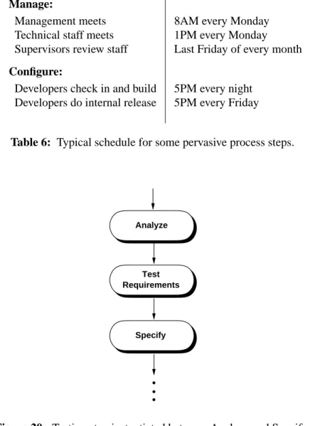
There are a variety of ways to depict a process. A typical graphical depiction uses a diagram with boxes and arrows, as shown in Figure 1. In this style of diagram, a process step is shown as a rounded box, and the order of steps is depicted with the arrowed lines. Process sub-steps are typically shown with a box expansion notation. For example, Figure 2 shows the expansion of the "Analyz e and Specify" step. The activities of the first sub-step include general aspects of requirements analysis, such as defining the overall problem, identifying personnel, and studying related products. The second sub-step defines functional requirements for the way the software actually works, i.e., what functions it performs. The last sub-step defines non-functional requirements, such as how much the product will cost to develop and how long it will take to dev elop. This expansion is an over-simplification for now, since there are more than three sub-steps in "Analyz e and Specify". A complete process expansion is coming up a bit later in this chapter. A more compact process notation uses mostly text, with indentation and small icons to depict sub-step expansion. Figure 3 shows a textual version of the general process, with the first step partially expanded, and other steps unexpanded. Right-pointing arrowheads depict an unexpanded process step.
Analyze and Specify Software Requirements Define Functional Requirements Define Non-Functional Requirements Perform General Requirements Analysis
Figure 2: Expansion of the ‘‘Analyze and Specify’’ Step.
Define Non-Functional Requirements Analyze and Specify Software Requirements
Perform General Requirements Analysis
Identify People Involved Analyze Operational Setting Analyze Impacts
Identify Positive Impacts Identify Negative Impacts
Analyze Feasibility Analyze Related Systems State Problem to be Solved
Define Functional Requirements
Design and Implement Software Product Test that Product Meets Requirements Deploy, Maintain, and Enhance the Product
Figure 3: Te xtual process depiction.
pointing arrowheads depict a process step with its sub-steps expanded immediately below. A round bullet depicts a process step that has no sub-steps.
Depending on the context, one or the other form of process depiction can be useful. When the emphasis is on the flow of the process, the graphical depiction can be most useful. To show complete process details, the textual depiction is generally more appropriate.
An important property of the textual depiction is that it can be considered unordered in terms of process step enactment. In the graphical process depiction, the directed lines connote a specific ordering of steps and sub-steps. The textual version can be considered more abstract, in that the top-to-bottom order of steps does not necessarily depict the specific order in which steps are enacted.
Given its abstractness, the textual depiction of a process can be considered the canonical form. Canonical form is a mathematical term meaning the standard or most basic form of something, for which other forms can exist. In the case of a software process, the canonical process form is the one most typically followed. The process can vary from its canonical form in terms of the order in which the steps are fol-lowed, and the number of times steps may be repeated.
Consider the three major sub-steps of underAnalyz e and Specifyin Figure 3. The normal order of these steps is as listed in the figure. This means that "Perfor m General Requirements Analysis", is normally performed before "Define Functional Requirements" and "Define Non-Functional Requirements". How-ev er in some cases, it may be appropriate to analyze the non-functional requirements before the other steps, or to iterate through all three of the steps in several passes. The important point is that in abstract-ing out a particular enactment order, the textual process depiction allows the basic structure of the process to be separated from the order of enactment.
2.1.3. Styles of Process Enactment
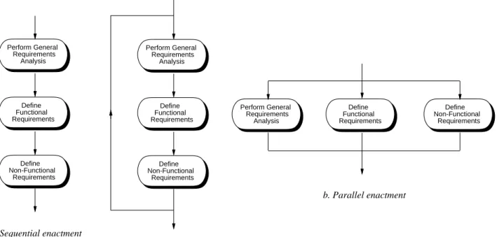
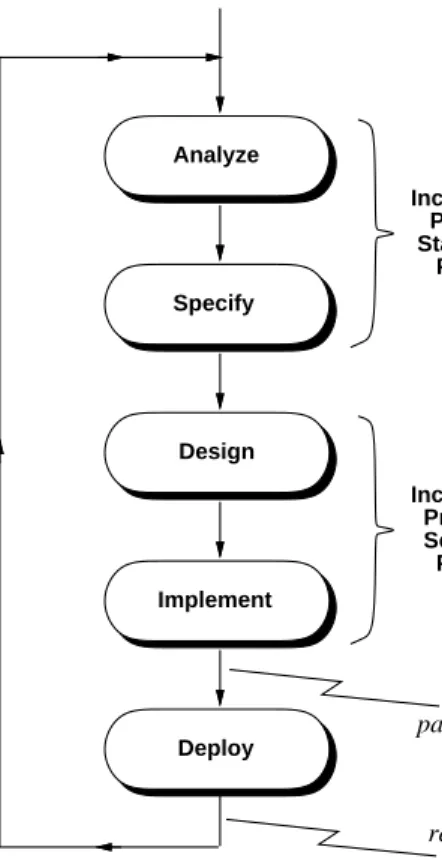
Once the steps of a software process are defined, they can be enacted in different ways. The three general forms of ordered enactment are sequential, iterative, and parallel. These are illustrated in Figure 4 for the three sub-steps of theAnalyz e and Specifystep.
Sequential enactment means that the steps are performed one after the other in a strictly sequential order. A preceding step must be completed before the following step begins. For the three steps in Figure a, this means that the general analysis is completed first, followed by functional requirements, followed by non-functional requirements. Perform General Requirements Analysis Define Functional Requirements Define Non-Functional Requirements a. Sequential enactment b. Parallel enactment Perform General Requirements Analysis Define Functional Requirements Define Non-Functional Requirements b. Iterative enactment Perform General Requirements Analysis Define Functional Requirements Define Non-Functional Requirements
Iterative enactment follows an underlying sequential order, but allows a step to be only partially com-pleted before the following step begins. Then at the end of a sequence, the steps can be re-enacted to complete some additional work. When each step is fully completed, the entire sequence is done. In Fig-ure b, some initial work on general analysis can be completed, enough to start the function requirements analysis. After some functional requirements are done, work on the non-functional requirements can begin. Then the three steps are repeated until each is complete.
Parallel enactment allows two ore more steps to be performed at the same time, independent of one another. When the work of each step is completed, the process moves on to the subsequent steps.
Which of these enactment styles to use is determined by the mutual dependencies among the steps. For some projects, the determination may be made that a complete understanding of the general requirements is necessary before the functional and non-functional requirements begin. In this case, a strictly sequen-tial order is followed. In other projects, it may be determined that general requirements need only be par-tially understood inipar-tially, in which case an in iterative order is appropriate.
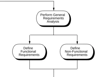
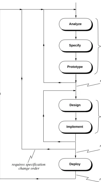
In this particular example that deals with analysis, a purely parallel order is probably not appropriate, since at least some understanding of the general requirements is necessary before functional and non-functional requirements are analyzed. Given this, a hybrid process order can be employed, such as shown in Figure 5. In this hybrid style of enactment, a first pass at general analysis is performed. Then the func-tional and non-funcfunc-tional analysis proceed in parallel. The process then iterates back to refine the general requirements and then proceed with further functional and non-functional refinements.
The three styles of process enactment discussed so far apply to process steps that are performed in some order relative to one another. A fourth kind of enactment is pervasive. A pervasive process step is per-formed continuously throughout the entire process, or at regularly scheduled points in time. A good example of pervasive process steps are those related to project management. A well managed project will have regularly-scheduled meetings that occur on specific scheduled dates, independent of what specific ordered step developers may be conducting. The steps of the process dealing with project supervision occur essentially continuously, as the supervisors oversee developer’s work, track progress, and ensure
Perform General Requirements Analysis Define Functional Requirements Define Non-Functional Requirements
that the process is on schedule.
Testing is another part of the software process that can be considered to be pervasive. In some traditional models of software process, testing is an ordered step that comes near the end, after the implementation is complete. The process used in this book considers testing to be a pervasive step that is conducted at regu-larly schedule intervals, throughout all phases of development.
The people who make the determination of a which style of enactment to use are those who define the process in the first place. Process definers are generally senior technical and management staff of the development team. These are the people who understand the type of software to be developed and the capabilities of the staff who will develop it. The remaining sections of this chapter contain further discus-sion on the rationale for choosing different styles of process enactment, as well as different overall process structures.
2.2. Defining a Software Process
This book presents and follows a specific software process. The purpose of presenting a particular process is three-fold:
a. to define a process that is useful for a broad class of end-user software, including the example soft-ware system presented in the book
b. to provide an organizational framework for presenting technical subject matter
c. to give a concrete example of process definition, that can be used for guidance in defining other software processes
Defining a software process entails the following major tasks: defining the process steps, defining process enactment, and defining the artifacts that the steps produce. Process steps and their enactment are defined here in Chapter 2. The structure of software artifacts is presented in Chapter 3.
An important point to make at the outset is that this is "a" software process, not "the" process. There is in fact no single process that is universally applicable to all software. The process employed in this book is useful for a reasonably wide range of end-user products. However, this process, as any other, must be adapted to suit the needs of a particular development team working on a particular project. A good way to regard the process is as a representative example of process definition. Further discussion of process adaptation appears later in the chapter.
One of the most important things to say about software process is "use one that works". This means that technical details of a process and its methodologies are often less important than how well the process suits the project at hand. Above all, the process should be one that everyone thoroughly understands and can be productive using. There is no sense having management dictate a process from on high that the customers and technical staff cannot live with. The management and technical leaders who define a soft-ware process must understand well the people who will use it, and consult with them as necessary before, during, and after the establishment of a process. In order for all this to happen, the process must be clearly defined, which is what this chapter is about.
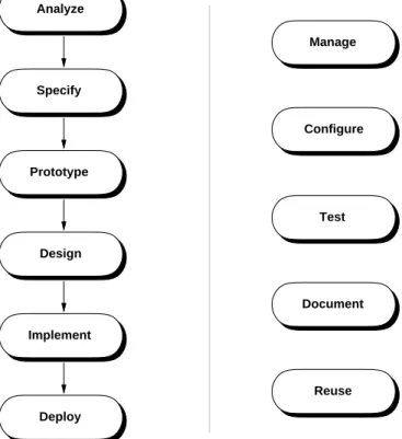
The top-level steps of the book’s process are shown in Figure 6. These steps are a refinement of the gen-eral software process presented at the beginning of the chapter in Figure 1. The refined process has the following enhancements compared to the more general one:
• the "Analyze and Specify" step has been broken down into two separate steps; • similarly, the "Design and Implement" step has been broken into two separate steps;
Analyze Specify Design Implement Prototype Deploy Manage Configure Document Reuse Test Ordered Steps: Pervasive Steps:
Figure 6: Top-level steps of the process used in the book.
• step names have been shortened to single words for convenient reference;
• prototyping and deployment steps have been added, details of which are discussed shortly;
• testing has been made a pervasive step of instead an ordered step following implementation; this sig-nifies that testing will be carried out at regularly scheduled points throughout the process, not just after the implementation is completed;
• additional pervasive steps have been added for the process activities that manage the software project, configure software artifacts, document the artifacts, and reuse existing artifacts.
From a problem solving perspective, theAnalyz eandSpecifysteps taken together constitute the problem definition phase; the Design and Implement steps together comprise the problem solution phase. The new Prototype step is a "pre-solution", where the developers rapidly produce a version of the product with reduced functionality. The purpose of the prototype is to investigate key product features before all of the details are finished. TheDeploystep elevates the process from one of plain problem solving to one that delivers a working product to the end users, once the implementation is completed.
The type of software for which the book’s process is specifically suited can be characterized as medium-scale information processing with a substantial end-user interface. This category of software covers a sig-nificant percentage of commercially available and public domain software that people use. The major characteristics of this type of software are the following:
• a substantial end-user interface, with a reasonably wide range of interface elements; the interface is typically a GUI (graphical user interface)
• information processing functionality that requires the following development techniques to be employed:
ο advanced techniques for data modeling and data design, including interface to external and remote databases
ο advanced techniques for functional modeling and functional design, including distributed pro-cessing, event-based propro-cessing, exception handling
• a sufficiently large size and scope to require the following process activities:
οdevelopment by multi-person teams
οthe use of techniques to develop non-trivial requirements specification artifacts, including large electronic documents and formal requirements models
ο the use of non-trivial design and implementation techniques, including use of multiple design patterns
οthe use of non-trivial testing techniques
οthe use of non-trivial project management, configuration control, and documentation practices The process is suitable for the development of software using general techniques of Computer Science. The process is not targeted to software that requires sophisticated specialized techniques, such as artificial intelligence or computer graphics. When knowledge in such fields is necessary, suitable experts need to be added to the development staff.
The process is not entirely suited to systems software, embedded software, highly experimental software, or small-scale software. In the case of systems and embedded software, aspects of the process that focus on human interface requirements are largely or wholly irrelevant. As explained in the introduction, sys-tems and embedded software have little or no requirements for human-computer interaction. There are also technical details of systems and embedded software that this process does not explicitly focus upon. These include steps to analyze operating system and computer hardware requirements that systems and embedded software must meet.
Highly experimental software is characterized by an incomplete understanding of what the software is going to do before it is built. Given this characterization, it is difficult or impossible to have a full set of requirements before implementation of experimental software begins. The process of developing experi-mental software can be thought of as turning the ordered process in Figure 6 on its head. The experimen-tal process starts with an implementation, which entails writing pieces of program to exhibit some sort of experimental behavior. When part of a working implementation is completed, the developers examine the experimental behavior to see what requirements can emerge, so that the experimental behavior can be refined and expanded. This iterative process continues until the developers are satisfied with the pro-gram’s behavior as implemented.
Very often, an experimental program is poorly designed, in terms of design standards that software engi-neers typically consider acceptable. Poor design can make a program difficult and expensive to maintain. In addition, experimental programs are often inefficient in terms of execution speed, since little considera-tion was given to engineering techniques that produce efficient programs. Given the deficiencies of exper-imental software, an experexper-imental development process can be followed by a traditional ordered process, if the developers believe that the experimental program forms a suitable basis for a production-quality product. The idea is that the experimental development leads to better understanding of product require-ments in an experimental domain. This understanding can then be applied in a traditional development
process, where the requirements are more fully analyzed, a maintainable design is developed, and an effi-cient implementation produced.
The other type of software to which the book’s process is not well suited is small-scale or medium-scale software with the following characteristics:
• dev elopment is conducted by one or a few people
• the roles of user, domain expert, analyst, and implementor are filled by the same person or a small number of persons
The development of computer game software can be a good example of this category. For this type of software, the developers are very often avid users themselves. They fully understand the application domain, and are able to transfer requirements ideas directly from their own imagination to a working pro-gram. For this type of development, the traditional process covered in this book may well be overkill. Despite the unique characteristics of different types of software, there are certain aspects of the book’s process that are nearly universally applicable. For example, the use of design patterns and the definition of program API are good practices for almost any type of software, except for the most highly experimen-tal. As later chapters of the book cover the process in detail, the issues of process applicability and adapt-ability will be discussed further.
As noted earlier, software engineers must always strive for a process that is well-suited to their develop-ment team and software product. Process definers must continually adapt what they hav e learned in gen-eral about processes to their specific projects at hand. For software projects that are similar to the book’s example, adapting the book’s process may only be a matter of changing a few details. For other projects, adapting the process may involve major changes, such as adding or deleting steps, or changing the order of the steps.
The way software process is presented and employed in this book is idealized. The presentation can be likened to the way a mathematician presents a complicated proof. Often, the process of conducting the proof is quite messy, with ideas coming from all directions. When the proof is finally published, the author lays things out in a nice neat order, so it can be clearly understood. In a similar manner, the author of this book has laid the software process out in a nice neat order, again for the purpose of clearly under-standing it.
Software engineers must be keenly aware that applying a software process in actual practice can indeed get messy. For this reason, those who oversee the project need to be flexible, and prepared to make adjustments to the process as a project is underway. Fine-tuning adjustments are almost always necessary, in response to normal occurrences like scheduling or staffing changes. Any major changes to a process midstream in a project must be more carefully considered, and the management staff must use good judg-ment when making such changes. Never the less, all project participants must be be prepared to change and adapt their process during the course of a project.
The next two sections of this chapter present an overview of the book’s software process, presenting all of its steps but without delving into details. Chapter 3 presents an overview of the artifacts produced by the process. Chapters 4 and beyond then focus on process and artifact details in the context of the technical discussion related all of the process steps. Chapter 25 includes coverage of process evaluation and improvement, as well as details that further formalize the process. In summary, the process definition in this chapter presents the "big picture", with further process details appearing throughout the book.
2.3. Ordered Process Steps
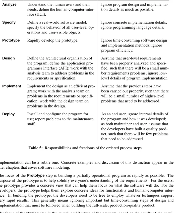
Figure 7 is a one-level expansion the ordered process steps. The ordered steps can be viewed as a process of successive refinement, from an initial idea through to a deployable software product. In this sense, the process is based on a divide and conquer strategy, where the focus of each step is a particular aspect of the overall development effort. At each step, the developers have the responsibility to focus on what is important at that level of refinement. They also have the freedom to ignore or give only limited consider-ation to what is important at other levels of refinement. Table 5 summarizes the responsibilities and free-doms for each top-level step of the ordered process.
The focus of theAnalyz estep is on user requirements. The needs of the user are the primary concern at this level. Concern with details of program design and implementation should be limited to what is feasi-ble to implement. For projects that are on a particularly tight budget or time line, requirements analysts may need to focus more on implementation feasibility. Also, it may be difficult to estimate implementa-tion feasibility if the analysis team is inexperienced in the type of software being built or in the applica-tion domain. In such cases, a more iterative dev elopment approach can be useful, as is discussed a bit later in this chapter.
The focus of the Specify step is on building a "real-world" software model. Real-world in this context means that the model defines the parts of the software that are directly relevant to the end user, without program implementation details. The distinction between a real-world model and program
Analyze
Perform General Requirements Analysis Define Functional Requirements Define Non-Functional Requirements Specify
Specify Structural Model Specify Behavioral Model Specify User Interface Model
Specify Non-Functional Requirements Iterate Back to Analyze Step as Necessary Prototype
Refine Scenario Storyboards into Working UI Sequence UI Screens
Sensitize UI Components Write Prototype Scripts
Iterate Back to Preceding Steps as Necessary
Design
Design High-Level Architecture Apply Design Patterns
Refine Model and Process Design Refine User Interface Design Formally Specify Design
Design for Non-Functional Requirements
Define SCOs, Iterate Back as Necessary Implement
Implement Data Design Implement Function Design Optimize Implementation Apply Design Heuristics
Iterate Back to Design Step as Necessary Define SCOs, Iterate Back as Necessary Deploy
Release Product Track Defects Define Enhancements
Iterate Back to Repair and Enhance
Step Responsibilities Freedoms Analyz e Understand the human users and their
needs; define the human-computer-inter-face (HCI).
Ignore program design and implementa-tion details as much as possible.
Specify Define a real-world software model; specify the behavior of all user-level op-erations and user-visible objects.
Ignore concrete implementation details; ignore programming language details.
Prototype Rapidly develop the prototype. Ignore time-consuming software design and implementation methods; ignore program efficiency.
Design Define the architectural organization of the program; define the application pro-grammer interface (API); work with the analysis team to address problems in the requirements or specification.
Assume that user-level requirements have been properly analyzed and speci-fied, such that there will be a small num-ber requirements problems; ignore low-level details of program implementation.
Implement Implement the design as an efficient pro-gram; work with the analysis team on problems in the requirements or specifi-cation; work with the design team on problems in the design.
Assume that the previous steps have been carried out properly, such that there will be a small number of higher-level problems that need to be addressed.
Deploy Install and configure the program for use; report problems to the maintenance staff.
As an end user, ignore internal details of the program and how it was developed; as both maintainer and user, assume that the developers have built a quality prod-uct, such that there will be few problems that need to be addressed.
Table 5: Responsibilities and freedoms of the ordered process steps.
implementation can be a subtle one. Concrete examples and discussion of this distinction appear in the later chapters that cover software modeling.
The focus of the Prototypestep is building a partially operational program as rapidly as possible. The purpose of the prototype is to help solidify everyone’s understanding of the requirements. For the users, the prototype provides a concrete view that can help them focus on what the software will do. For the developers, the prototype helps them explore concrete ideas for functionality and human-computer inter-face. In building the prototype, the developers need to be free to employ whatever techniques support very rapid results. This generally means ignoring important but time-consuming steps of design and implementation that must be followed when building the full-scale, production-quality product.
The focus of theDesignstep is the overall architecture of the program, based on the results of the previ-ous steps of the process. A high-level architecture defines large-grain program units and the
interconnection between the units. A lower-level architecture defines further details, down to the level of the application program interface (API). The designers do not to focus on lower-level implementation details, such as concrete data structuring and the procedural implementation of program functions. The later chapters of the book on design discuss the different levels of the design process, the specific defini-tion of an API, and what constitutes design versus implementadefini-tion detail.
The focus of theImplement step is the algorithmic and data detail of an efficient program. The imple-mentors assume that previous steps have been conducted properly, so there will be a small number or problems that need to be addressed at the previous levels while the implementation is under way. In terms of the original idea of a problem-solving process, the implementors are free to assume that the problem has been well defined before they implement its solution.
The focus of theDeploystep is to put the developed product to use. This entails distribution, installation and, as necessary, maintenance. The maintenance may be carried out by a separate post-develop team, by the original developers, or by some combination of these. Users and maintainers alike should have the freedom to assume that the developers have built a quality product, that will work correctly and meet the users’ needs. Some will say that users have more than the freedom to assume quality, but the right to assume it, particularly when they pay for a software product. The issues of societal rights and responsi-bilities related to software are addressed in a later chapter on software engineering ethics and law.
Throughout the software process, there can be a delicate balance between the freedoms and responsibili-ties of the different process steps. Questions can arise in particular about how free the developers are to employ a purely divide-and-conquer subdivision of efforts. For example, how thoroughly do the analysts need to understand implementation issues in order to specify a product that is feasible to implement? How well can the analysts define the HCI when they do not fully understand the difficulties of HCI imple-mentation? Such questions will be addressed continuously in the upcoming chapters of the book, as the details of the process steps are further explored.
The preceding questions about software process are much like questions that arise in other engineering efforts. For example, building contractors regularly question the ability of architects to design buildings that can be constructed in an efficient and cost-effective manner. Civil engineers can question the tect’s ability to design a building that will stand up to external forces of nature. For their part, the archi-tects want the engineers and contractors to appreciate the architectural aesthetic of a building, even when that aesthetic may be difficult to implement.
When people confront difficulties in other engineering efforts, they do not abandon an overall divide-and-conquer strategy. Rather, they recognize that the process must take into consideration the interaction between the different development steps to ensure that the final product is successfully built. Software engineers are by no means alone in having to deal with the intricacies of a workable development process.
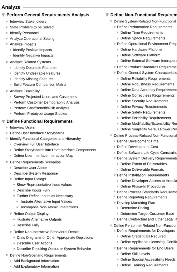
2.3.1. Analyz e
Figure 8 shows a full expansion of theAnalyz estep. This step starts by performing a general analysis of user requirements. The initial sub-step is to interview all participating stakeholders. After the initial interviews, communication with affected stakeholders will be an ongoing activity.
In keeping with the overall problem-solving process, the next sub-step of general analysis is to state the problem to be solved. This results in a succinct presentation of the specific problem(s) to be solved and the needs to be met by the software.
Analyze
Perform General Requirements Analysis Define Non-Functional Requirements
Define System-Related Non-Functional Requirements Define Performance Requirements
Define Time Requirements Define Space Requirements
Define Operational Environment Requirements Define Hardware Platform
Define Software Platform
Define External Software Interoperability Define Product Standards Requirements Define General System Characteristics
Define Reliability Requirements Define Robustness Requirements Define Data Accuracy Requirements Define Correctness Requirements Define Security Requirements Define Privacy Requirements Define Safety Requirements Define Portability Requirements
Define Modifiability/Extensibility Requirements Define Simplicity Versus Power Requirements Define Process-Related Non-Functional Requirements
Define Development Time Define Development Cost
Define Software Life Cycle Constraints Define System Delivery Requirements
Define Extent of Deliverables Define Deliverable Formats Define Installation Requirements
Define Developer Access to Installation Define Phase-In Procedures
Define Process Standards Requirements Define Reporting Requirements Develop Marketing Plan
Determine Pricing
Determine Target Customer Base
Define Contractual and Other Legal Requirements Define Personnel-Related Non-Functional Requirements
Define Requirements for Developers Define Credentials Required
Define Applicable Licensing, Certification Define Requirements for End Users
Define Skill Levels
Define Special Accessibility Needs Define Training Requirements Identify Personnel
Analyze Operational Setting Analyze Impacts
Identify Positive Impacts Identify Negative Impacts
Analyze Feasibility
Survey Projected Users and Customers Perform Customer Demographic Analysis Perform Cost/Benefit/Risk Analysis Perform Prototype Usage Studies Analyze Related Systems
Identify Desirable Features Identify Undesirable Features Identify Missing Features Build Feature Comparison Matrix
Define Functional Requirements
Interview Users
Define User Interface Storyboards
Identify Functional Categories and Hierarchy
Define Requirements Scenarios Overview Full User Interface
Refine Storyboards into User Interface Components
Describe User Action Describe System Response Refine Input Dialogs
Define User Interface Interaction Map
Show Representative Input Values Describe Inputs Fully
Further Refine Inputs as Necessary Illustrate Alternative Input Values Decompose Non-Atomic Interactions Refine Output Displays
Illustrate Alternative Outputs
Refine Non-Interactive Behavioral Details Draw Diagrams or Other Appropriate Depictions Describe User Actions
Describe Resulting Output or System Behavior State Problem to be Solved
Describe Fully
Define Non-Scenario Requirements Add Background Information Add Explanatory Information Interview Stakeholders
Following the general problem statement, the analysts identify the personnel involved with the project. These are all stakeholders who will be participating in the project. The specific list of stakeholders can be organized using the categories presented in Section 1.2 of the Introduction.
Analyzing the operational setting entails characterizing the human and computing environment in which the software is to be used. The human environment is the organization who will use custom software, or the general user community who will use an off-the-shelf product. The discussion of the setting includes how operations are conducted in the environment before and after the software is installed. The following questions are addressed:
a. What computer-based support is in use prior to installation of the new system?
b. Does the new system need to interface with existing software or is the existing software to be replaced entirely?
The impact analysis sub-step assesses the impacts of the software within its operational setting. Both pos-itive impacts (e.g., increased productivity, higher product sales) as well as negative impacts (e.g., job dis-placement, potential negative leg al impacts) are addressed.
The analysis of related software requires identification of existing software that provides functionality similar or related to the functionality of the software being proposed. The following issues are addressed: a. What is good about the related software, i.e., what features does it have that should be included in
the system software being proposed.
b. What is bad about the related software, i.e., what features should not be included in the proposed software, or what features should be included but done in a different or better way.
c. What is missing, i.e., what new features should be included in the proposed software that are not found in the related products.
If appropriate, related software can be overviewed in a feature comparison matrix. This is a table that lists all of the features of the related software, for the purposes of side-by-side comparison.
Feasibility analysis addresses issues related to the user community and, if appropriate, the commercial market for which the software is targeted. Some or all of the following sub-steps can be carried out;
a. surveys of projected users and customers, to determine their wants and needs
b. demographic analysis of customers, to determine the potential profitable market for an off-the-shelf product
c. cost/benefit/risk analysis to determine if the a profit can be made in the target market, and if the risks associated with the project are outweighed by the benefits
d. prototype usage studies, where potential customers use a system prototype to test their reactions Chapter 4 of the book covers the general analysis step in complete detail.
Following general analysis, the next major analysis sub-step is devoted to functional requirements. This is typically the part of the analysis that consumes the most time and energy.
Functional requirements define the specific functions that the software performs, along with the data oper-ated on by the functions. In the process defined here, the primary form for presenting functional require-ments is scenarios that depict an operational software system from the perspective of its end users. Included are one or more examples of all system features and an enumeration of all the specific require-ments associated with these features.
When formulating the initial ideas for a product, analysts use storyboards to work out the way a program will appear to its end users. Storyboarding is a practice borrowed from the movie industry, where a
director sketches out the scenes of a movie before it is filmed. In a similar way, a software analyst sketches out the user interface of a program before it is implemented.
Following the initial storyboarding, an overall functional hierarchy is dev eloped. In concrete terms, this is the top-level user interface to the software. In current practice, the top-level UI is very typically menu-based, but other forms are widely used, such as toolbars and control panels. As the functional hierarchy is developed, the initial sketched storyboards are refined into concrete user interface components, so that the user can view the requirements in explicitly user-centered terms, namely through the interface that the user will employ to communicate with the software.
A UI interaction map may be defined in this sub-step. An interaction map shows a thumbnail view of each interaction screen. The thumbnails are connected with directed arrows that describe the form of user interaction that leads from one screen to the next.
The specific methodology presents scenarios using action/response sequences. The action is performed by the user, the response is generated by the software system. The key steps of the scenario process are the following:
a. Describe an action performed by the user, such as selecting a menu item or typing in some data value.
b. Describe the the system response, such as displaying an information window or adding a value to some data collection.
c. When a system response is a request for user input, illustrate a representative set of sample input values, and define new scenarios around subsequent user actions.
d. When a system response is an output display, describe the output precisely and illustrate a repre-sentative set of alternative output forms, adding new scenarios for major output alternatives. To establish a complete definition of all functional requirements, the interaction scenarios are augmented with descriptions of the non-interactive system behavior. Non-interactive behavior is computation per-formed by the system that generates no immediate interactive response, such as internal computation or communicating with external programs.
To present a complete set of requirements, scenarios are augmented with additional content that is not in the action/response style . This portion of the requirements provides necessary background information and other explanatory details to make the requirements completely clear to all readers.
All system behavior is defined strictly in user-level terms, never in terms of an underlying program imple-mentation. The overriding rule is "If a user sees it , define it", otherwise consider it an implementation detail. What it means for a user to "see" a particular behavior or data value is that the user either sees it explicitly in visual form, or is aware of it based on computation performed by the system. Chapter 5 describes the functional requirements process in full detail, augmented with many concrete examples. The third sub-step of theAnalyz eis devoted to non-functional requirements. These requirements address aspects of the system other than the specific functions it performs. Aspects include system performance, costs, and such general system characteristics as reliability, security, and portability. The non-functional requirements also address aspects of the system development process and operational personnel.
There are three major categories of non-functional requirements, corresponding to the three sub-steps of the non-functional process:
• system-related -- these are non-functional requirements related to the software itself, such as perfor-mance, operational environment requirements, product standards, and general system characteristics • process-related -- these are requirements for the software development process, including how long
it will take, how much it will cost, and other relevant matters
• personnel-related -- these are requirements related to the people involved with software develop-ment and its use
There are a number of details shown Figure 8 that have not been fully enumerated in the preceding over-view. Complete details of the non-functional process are covered in Chapter 6.
In comparing theAnalyz estep of the process to the other major steps that follow, it has more details, par-ticularly in the area of non-functional requirements. The reason for this is that the requirements phase defines general project goals and product requirements that are broadly applicable to most types of soft-ware. Once these goals are established, they apply to the overall process and product being developed, throughout the subsequent development steps. In effect, the subsequent steps carry forward the goals established in the definition of the requirements.
2.3.2. Specify
Figure 9 shows a full expansion of theSpecifystep. The Specify step of the process involves the devel-opment of a formal model of the requirements. The purpose of the model is two-fold:
• it helps the analysts uncover flaws and omissions in the requirements;
• it defines the formal specification that can be used as a contract with implementors.
In the process of this book, the formal model is defined in a language that can be mechanically analyzed. The analyzer checks the model in basically the same way that a compiler checks a program. Namely, it checks the syntax and some aspects of the semantics of the model. This mechanical analyzer helps the human analyst find flaws and omissions in the model.
The idea of the specification forming a contract with the implementors is extremely important when it comes time to verify that a delivered software product meets its requirements. When the requirements are distilled into a formal specification, then the process of testing the implementation against its specification is much more rigorous then when requirements are defined in a less formal form, such as only English and pictures.
The two main sub-steps ofSpecifyinvolve the construction of structural and behavioral software models. The structural model defines the static structure of the software. The behavioral model defines precisely the way the software behaves in terms of the inputs it receives and the outputs it produces.
The structural model is derived initially from the requirements scenarios using some general derivation heuristics. A heuristic is a "rule of thumb" that defines in general terms how to perform some task. The heuristics for model derivation define how model objects, operations, and attributes are derived from the user-centered requirements scenarios. An object is the formal definition of a user-visible piece of data. An operation is the formal definition of an action performed by the software using the objects. In particu-lar, operations take objects as inputs and produces objects as outputs. A model attribute is a general char-acteristic of the software.
Once model objects, operations, and attributes are derived from scenarios, they are refined further based on the detailed scenario narrative. This part of the process very typically involves a significant amount of iteration with theAnalyz estep, that proceeds in high-level terms like this:
a. Define a requirements scenario.
b. Derive objects, operations, and attributes, leading to the discovery of flaws or omissions in the sce-narios.
Specify
Specify Structural Model
Derive Input Objects from Data-Entry Dialogs Derive Output Objects from Data Output Displays Derive Objects from Requirements Scenarios
Derive Operations from Scenarios
Derive Operations from Menus and Buttons Derive Other Operations from Narrative Verbs
Refine Operations
Specify Inputs and Outputs Identify Default Inputs
Add Descriptions Based on Narrative Refine Objects
Define Component Details to Atomic Level Identify Underlying Collection Objects Define Inheritance from Generic Objects Add Descriptions Based on Narrative Derive Other Objects from Narrative Nouns
Specify Behavioral Model Define Predicative Specification
Derive Preconditions and Postconditions
Define Inter-Operation Specification Refine Conditions into Formal Logic
Refine Object and Operation Definitions as Necessary
Refine Preconditions and Postconditions Define Inter-Operation Dataflow Define Auxiliary Functions as Necessary
Define Equational Specification Define Object Equations
Define Auxiliary Functions as Necessary Define Axiomatic Specification
Define Global Variables Define Axioms
Sketch Conditions as Prose Comments
Modularize Structural Model Define Module Packaging
Specify Module Imports Define Auxiliary Functions as Necessary
Specify Non-Functional Requirements Iterate Back to Analyze Step as Necessary
Define User Interface Behavior Define User Interface Structure Specify User Interface Model
Define Attribute Grammar Specification Define Attributes
Define Rules
Define Attribute Equations
Define Constructive Functional Specification
Define Auxiliary Functions as Necessary Define Operations Functionally
Define Auxiliary Functions as Necessary Derive Model Attributes from Scenarios
Refine Attributes
Figure 9: The Specify step fully expanded.
new scenarios for the omitted functionality.
The final sub-step of structural modeling is the modularization of the model into functionally-related packages of objects and operations. This model packaging is used subsequently in the design step to derive the initial program architecture.
Specifying the behavioral model is where the specification becomes fully formal. In the process shown in Figure 9, the main form of behavioral specification is called predicative. A "predicate" is a boolean expression, of the type familiar to all programmers. There are some additional details to the language of predicates used in formal specification, but fundamentally a predicate simply states a condition that must be true or false.
A predicative specification defines two types of conditions for program behavior. A precondition must be true before an operation executes, and a postcondition must be true after an operation completes its execu-tion. Using just these two forms of condition, a formal definition can be specified for most of a program’s behavior. The specification can be further refined by enacting one or more additional process steps. These additional steps address the following aspects of specification:
• inter-operation behavior -- this is the definition of the way in which operations interact with one another; a dataflow diagram can be used to specify the way the outputs of operations feed into the inputs of other operations
• equational specification -- this defines specific constraints on objects in terms of what the operations are allowed to do with and to the objects
• axiomatic specification -- this defines formal rules, i.e., axioms, that can be particularly useful in specifying the behavior of distributed and concurrent software
• attribute grammar specification -- this defines a model in terms a formal language definition that is part of the software; for example, a query language that is part of a database software system can be defined using an attribute grammar
• constructive functional specification -- this form of specification is useful when certain details of behavior are most easily specified in operational terms; a constructive specification is a form of very high-level program
There are other forms of behavior specification not explicitly cited in this process. These include behav-ioral specifications based on state machines, stochastic techniques, and temporal logic. These forms of specification are explained and discussed in a later chapter, but not employed in the book.
The third sub-step ofSpecifyis devoted to the specification of a user interface model. It is important in software specification and design to separate the details of abstract functionality from concrete user inter-face. For this reason, the specification of user interface structure and behavior is separated from the speci-fication of the underlying functional model. This separation is reflected significantly in theDesignstep of the process, as will be explained shortly.
The fourthSpecifystep is the definition of those non-functional requirements that can be formally mod-eled. This includes the specification of such model properties as the size of data objects, and the speed at which operations must execute. Such formal model attributes form a bridge between functional and non-functional requirements. In general, non-functional requirements can be specified fully formally, whereas non-functional requirements may be specified only partially formally.
The last step ofSpecifyshown in Figure 9 is not an actual operative step, but an indication that the Spec-ifystep is likely to be part of an iterative process involving the Analyz e step. While the iteration may occur at any point duringSpecify, it is listed at the end as a general indication that iteration is a normal part of the combinedAnalyz eandSpecifyphase of the process. Further details of ordered process enact-ment are discussed in Section 2.5.1.
2.3.3. Prototype
The full expansion of thePrototypestep appears in Figure 7 since it does not expand beyond one level. As outlined earlier in Chapter 2, prototyping involves the rapid creation of a partially operational pro-gram. The prototyping process begins by refining scenario pictures into a working user interface. This entails using a prototyping tool or user-interface builder to create operational interface screens.
To create a very basic form of prototype, the interface screens can be presented in a step-by-step sequence, illustrating a particular set of prototypical interactions. This form of prototype is a "slide show"
of user interaction, that does not allow the user to interact dynamically with the prototype.
To create a more dynamically interactive prototype, the components in the interface screens can be
sensi-tized, such that the user may treat them like operating elements of the user interface. Certain prototyping
tools allow plain interface pictures to be sensitized. For example, the drawn picture of a button in an interface screen can be sensitized to behave like an actual clickable button. Alternatively, the prototype developer can use an interface building tool, where an operational prototype interface is created to have the same appearance as the screens drawn in the scenarios. In either case, the result is an interface with which end users can directly interact.
To define actual program behavior, the prototype developer writes action scripts that are associated with particular interface components. For example, suppose prototype interface contains a button labeled "Find" that when pressed displays the result of some search operation. The script for Findbutton can be defined to display an interface screen that shows a prototypical search result, thereby simulating a pro-totypical behavior. This type of prototype presents completely "canned" behavior. That is, the prototype responds to user interaction by displaying only pre-defined results, without performing any actual compu-tation.
To define a prototype with uncanned behavior, the scripts can extended to perform actual computation. In the case of search example, the script for the Find button is written to search some form of prototype data store, and present the results of the actual search. The representation of the prototype data store is some form that can be rapidly developed, without regard for storage efficiency or other data storage requirements that cannot be rapidly implemented.
For some types of software, it may be possible to evolve a prototype into a production product by reusing some or all of the prototype interface and scripting. This is an evolutionary style of prototyping. When little or none of a prototype can be reused in the production software, the prototype is considered a
throw-away. Once a throw-away prototype has served its purpose, that is to clarify the requirements, the
proto-type is discarded.
Whether the prototype evolves or is discarded, its use in requirements clarification is primary. For this reason, the last step of thePrototypeprocess is to iterate back to theAnalyz eandSpecifysteps, so that what is learned from the prototype can be integrated into the requirements and specification.
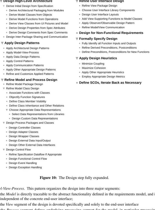
2.3.4. Design
Figure 10 is a full expansion of theDesignstep. The step starts by deriving the high-level architecture of the program from the abstract model constructed in theSpecifystep. The modularization defined for the structural model is carried forward into the packaging of the program design. This enforces traceability between the abstract specification and the corresponding architectural program design.
The high level architecture of a program is defined in terms of data classes and computational functions. These are derived, respectively, from the objects and operations of the specification. The classes and functions derived directly from the specification constitute the model portion of the design. The classes derived from concrete user interface and UI model are the view portion of the design. Other properties of the design are derived from attribute definitions in the specification. In addition, the commentary in the specification is used as the basis for design comments.
Once the top-level design elements are derived from the requirements specification, software design pat-terns are applied. A design pattern is a pre-packaged piece of design, based on experience that has been gained over the years by software engineers. A widely-used design pattern for end-user software is
Design
Design High-Level Architecture
Derive Architectural Packaging from Modules Derive Model Classes from Objects Derive Initial Design from Specification
Design Inter-Package Sharing and Communication Derive Model Functions from Operations
Apply Communication Patterns
Apply Other Appropriate Design Patterns Refine and Customize Applied Patterns Apply Architectural Design Patterns Apply Model-View-Process Apply Data Design Patterns Apply Control Patterns
Apply Design Patterns
Refine Model and Process Design
Derive View Classes from UI Pictures and Model
Choose Appropriate Data Representations Associate Functions with Classes Objectify Function Signatures Define Class Member Visibility
Define Class Inheritance and Other Relations
Select Data Representations from Libraries Design Custom Data Representations
Design Controller Classes Design Adaptor Classes Design Wrapper Classes Design External Data Input/Output
Refine Specification Dataflow If Appropriate Design Functional Control Flow
Design Event Handling Design Exception Handling
Design Process Packages and Classes
Design Control Flow Refine Model Class Design
Design Other External Data Interfaces
Refine User Interface Design
Choose User Interface Library Components
Minimize Coupling Maximize Cohesion
Apply Other Appropriate Heuristics Employ Appropriate Design Metrics Fully Identify all Function Inputs and Outputs Refine Derived Preconditions, Postconditions
Define Preconditions, Postconditions for New Functions Design User Interface Layouts
Add View-Supporting Functions to Model Classes Apply Observer/Observable Design Pattern
Formally Specify Design
Apply Design Heuristics
Refine Model Package Design
Refine View Package Design
Define SCOs, Iterate Back as Necessary
Derive Design Properties from Spec Attributes
Derive Design Comments from Spec Comments Design for Non-Functional Requirements
Refine Model/View Communication
Figure 10: The Design step fully expanded. Model-View-Process. This pattern organizes the design into three major segments:
• the Model is directly traceable to the abstract functionality defined in the requirements model, and is independent of the concrete end-user interface;
• the View segment of the design is devoted specifically and solely to the end-user interface
that encapsulates platform-dependent aspects of the design.
Other patterns are employed to assist with design of program data, control, and communication.
The derived, pattern-based design produced by the first two steps must be refined into a concrete, object-oriented program design. This is accomplished in the next two design steps. At the high-level design, derived packages must be refined. At the class level, derived functions must be associated with specific model classes. This step is necessary since the operations of the functional specification do not necessar-ily belong to specific objects. Functions associated with classes become class methods, with appropriate adjustment to method signatures based on object-oriented design concepts. Other necessary design refinements are in the areas of class member visibility, inheritance, and the selection of concrete data rep-resentations. In a modern program design, data representations are typically selected from reusable pro-gram libraries.
Process class design entails determining the underlying processing support that is necessary to produce an efficient program. To encapsulate platform-dependent data processing, process classes are interfaced with model classes via controller, adaptor, and wrapper classes. These model/process interface classes encap-sulate aspects of the program that are specific to specific operating systems, hardware platforms, and external data stores.
An important part of model and process refinement is detailed control flow design. This includes the design of inter-class data flow, functional control flow, event handling, and exception handling.
The fourth step of design is devoted to refining the end-user interface. In the current state of the art, user interface design typically relies heavily on libraries of reusable interface classes. The class libraries define commonly-used interface elements and layouts. In a Model-View design, the model classes must be refined to support the view classes, based on the specifics of the user interface. A particularly useful design pattern in this regard is called "Observer/Observable". This pattern defines the way in which mul-tiple view classes can be systematically updated in response to data changes made by the user. Additional work in this design step involves refining the communication between model and view classes. This level of refinement focuses on how input data are sent from view classes into model classes, and how output data are sent from the model to the view.
The fifth design step focuses on system-related non-functional requirements. Non-functional require-ments that were formally modeled will already have been incorporated into the design as a result of the initial design derivation step. Also, certain design patterns may be oriented to the design of non-func-tional requirements, such as security. Any other non-funcnon-func-tional requirements that were not modeled in the specification or are not yet incorporated in the design are dealt with in this step. The purpose of this step is therefore to ensure that all system-related non-functional requirements are fully addressed in the design.
Once a detailed program design is established, the design is formally specified. This entails the precise definition of function (i.e., method) input/output signatures, followed by the specification of preconditions and postconditions for all functions. For the model functions derived directly from the specification, the function conditions are derived directly from the preconditions and postconditions defined in the derived-from operations. For other model and process functions, preconditions and postconditions are defined with the same methodology used in the abstract specification model. Namely, preconditions are expres-sions that must be true before function invocation; postconditions must be true after function executions. Various design heuristics (i.e., general guidelines) can be applied throughout the process of design. Mini-mizing coupling among program elements aims to reduce the dependency and communication to only that which is essential Maximizing cohesion means that program elements that are functionally related are
grouped together, without extraneous unrelated elements. Other heuristics can be applied, such as con-trolling the size of various program units.
During the course of program design, the developer may discover aspects of the requirements specifica-tion that need to be modified or enhanced. In such cases, the designer defines a specificaspecifica-tion change
order that clearly states the necessary modifications or enhancements. This formalized change order is in
keeping with the high-level process decomposition into problem definition and problem solution phases. As discussed earlier in this chapter, theAnalyz eandSpecifyprocess steps comprise the problem defini-tion phase. TheDesignandImplementsteps then comprise the problem solution phase. In this software process, as in a traditional problem-solving process, changing the problem definition while the solution is underway requires careful consideration. The specification change order codifies this careful considera-tion in a precise way.
2.3.5. Implement
Figure 11 shows a full expansion of the Implement step. The Implement step fills in the operational details of the program by fully refining program data and functions. Implementing the data design requires the selection of fully concrete data structures for the representation of the data in all classes. This may in turn lead to the definition of new inheritance relations, and the design of lower-level classes to support an efficient implementation.
The implementation of the functional design involves the coding of all function bodies. This is the most concrete aspect of software programming. This typically leads to the definition of additional low-level
Implement
Implement Data Design
Define New Inheritance Relationships
Design and Implement Low-Level Support Classes Fully Refine Class Data Representations
Code Function Bodies
Define and Code New Functions
Refine Function Calling Hierarchy
Implement Function Design
Optimize Implementation
Subvert Information Hiding for Efficiency Apply Other Optimizing Transformations Inline Functions Where Appropriate
Formally Specify New Functions
Iterate Back to Design Step as Necessary Define SCOs, Iterate Back as Necessary
Formally Specify New Functions Code New Function Bodies
functions and classes, as the implementation details evolve.
As new functions are defined during implementation, they must be formally specified in same manner as during the design process. In general, as the refinement of the implementation leads to the definition of new classes and functions, the implementation process iterates back to design, where the appropriate design steps are applied to the newly-defined classes and functions.
A key aspect of function implementation is the refinement of the function calling hierarchy. As function implementations expand, it may well be necessary to subdivide the functions into additional sub-func-tions, and refine data implementations accordingly.
Techniques for optimizing the implementation include the use of inline functions, and partial subversion of information hiding where necessary for efficiency. Other optimizing techniques can be applied based on how strong the requirements are for implementation efficiency. Modern compilers can be relied on to perform a variety of optimizing transformation to improve program execution efficiency.
Iteration between design and implementation steps is a normal part of the process. As noted above, the iteration occurs as new classes and functions are defined during implementation. In addition, implemen-tation may reveal incompleteness of flaws in the higher-level design, requiring iteration back to the design.
If the need arises to modify or enhance the requirements specification during implementation, a specifica-tion change order is defined. The process then iterates back to an appropriate pre-design step.
The number of specific substeps within Implement is relatively smaller than any of the preceding ordered steps, particularlyDesign. The reason for this is that the design substeps can in effect be con-sidered implementation substeps as well. The implementation is the concrete realization of the design. Hence, the general steps of the implementation are applied to each specific element of the program cre-ated in theDesignstep.
2.3.6. Deploy
Figure 12 is a full expansion of Deploy. Deployment is the post-development phase of the ordered
Deploy
Release Product
Define Enhancements Track Defects
Report Bugs
Assign Repair Personnel
Determine Steps Needed for Repair, If Any
Iterate Back to Repair and Enhance
Notify Users Distribute Product Install Product