sigma-aldrich.com 595 North Harrison Road, Bellefonte, PA 16823-0048 USA Tel: (800) 247-6628 (814) 359-3441 Fax: (800) 447-3044 (814) 359-3044
Bulletin 826E
HPLC Troubleshooting Guide
How to identify, isolate, and correct the most common HPLC problems
CONTENTS:
Isolating HPLC Problems ... 2
How to Prevent Mobile Phase Problems ... 2
Isolating Pump Problems ... 3
Injector and Injection Solvents ... 3
Column Protection ... 3
Getting the Most from Your Analytical Column ... 3
Solving Detector Problems ... 4
Column Heater, Recorder ... 4
Keeping Accurate Records ... 4
Problem Index ... 4
HPLC Problems, Causes and Remedies ... 5-13 Restoring Your Column's Performance ... 14-15 Preventing and Solving Common Fitting Problems ... 16 A Selection of Column Protection Products ... 17-20
E000648
Although HPLC method development has been
im-proved by advances in column technology and
instru-mentation, problems still arise. In this guide we offer
you a systematic means of isolating, identifying, and
correcting many typical problems.
The important segments of an HPLC system are the
same, whether you use a modular system or a more
sophisticated unit. Problems affecting overall system
performance can arise in each component. Some
com-mon problems are discussed here. Solutions to these
problems are presented in easy-to-use tables.
Debubbler
Pump
Solvent Reservoir and Inlet Filters
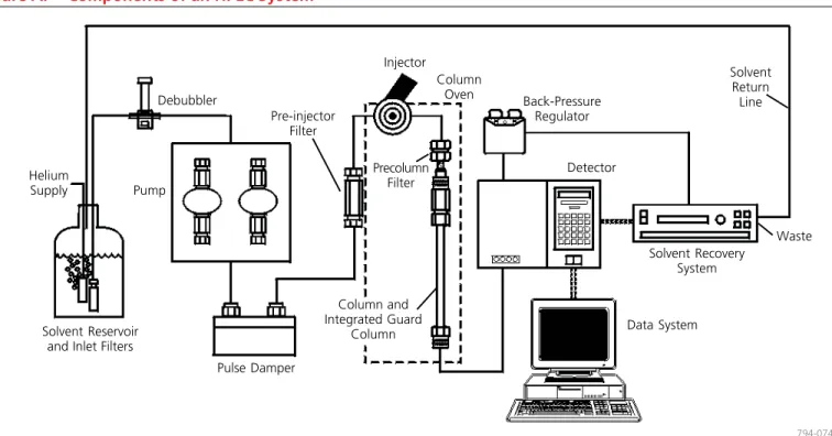
Pre-injector Filter Pulse Damper Column Oven Back-Pressure Regulator Detector Solvent Recovery System Data System Precolumn Filter Helium Supply Injector Waste 794-0746
Figure A.
Components of an HPLC System
Column and Integrated Guard Column Solvent Return Line
In an HPLC system, problems can arise from many sources. First define the problem, then isolate the source.
Use Table 1 (page 5) to determine which component(s) may be causing the trouble. A process of elimination will usually enable you to pinpoint the specific cause and correct the problem.
How to Prevent Mobile Phase Problems
Low sensitivity and rising baselines, noise, or spikes on the chro-matogram can often be attributed to the mobile phase. Contami-nants in the mobile phase are especially troublesome in gradient elution. The baseline may rise, and spurious peaks can appear as the level of the contaminated component increases.
Water is the most common source of contamination in reversed phase analyses. You should use only high purity distilled or deion-ized water when formulating mobile phases. However, several common deionizers introduce organic contaminants into the water. To remove these contaminants, pass the deionized water through activated charcoal or a preparative C18 column.
Use only HPLC grade solvents, salts, ion pair reagents, and base and acid modifiers. Cleaning lower quality solvents is time consuming, and trace levels of contaminants often remain. These trace contami-nants can cause problems when you use a high sensitivity ultraviolet or fluorescence detector.
Because many aqueous buffers promote the growth of bacteria or algae, you should prepare these solutions fresh, and filter them (0.2 μm or 0.45 μm filter) before use. Filtering also will remove particles that could produce a noisy baseline, or plug the column. Prevent microorganism growth by adding about 100 ppm of sodium azide to aqueous buffers. Alternatively, these buffers may also be mixed with 20% or more of an organic solvent such as ethanol or acetonitrile.
ally an in-line degasser is a first choice, but sparging with helium can be an alternative if the mobile phase does not contain any volatile components.
Use ion pair reagents carefully. The optimum chain length and concentration of the reagent must be determined for each analysis. Concentrations can be as low as 0.2 mM, or as high as 150 mM, or more. In general, increasing the concentration or chain length increases retention times. High concentrations (>50%) of acetoni-trile or some other organic solvents can precipitate ion pair re-agents. Also, some salts of ion pair reagents are insoluble in water and will precipitate. Avoid this by using sodium-containing buffers in the presence of long chain sulfonic acids (e.g., sodium dodecyl sulfate), instead of potassium-containing buffers.
Volatile basic and acidic modifiers, such as triethylamine (TEA) and trifluoracetic acid (TFA), are useful when you wish to recover a compound for further analysis. These modifiers also let you avoid problems associated with ion pair reagents. They can be added to the buffer at concentrations of 0.1 to 1.0% TEA or 0.01 to 0.15% TFA. Increasing the concentration may improve peak shape for certain compounds, but can alter retention times.
Recycling the mobile phase used for isocratic separations has become more popular in recent years as a means of reducing the cost of solvents, their disposal, and mobile phase preparation time. An apparatus such as the Supelco SRS-3000 or SRS-1000 Solvent Recovery System uses a microprocessor controlled switching valve to direct the solvent stream to waste when a peak is detected. When the baseline falls under the selected threshold, uncontaminated solvent is directed back to the solvent reservoir.
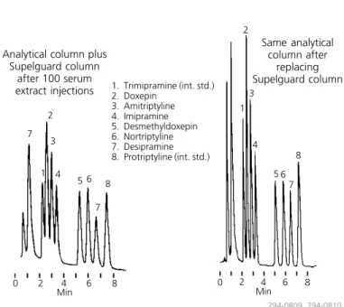
Figure B.
Supelguard Columns Prolong the Lifespan
of Your Analytical Columns
column: SUPELCOSIL LC-PCN, 25 cm x 4.6 mm I.D., 5 μm particles (with Supelguard LC-PCN guard column) (58378)
mobile phase: 25:60:15, 0.01 M potassium phosphate (pH to 7 w/85% phosphoric acid):acetronitrile:methanol
flow rate: 2 mL/min. temp.: 30 °C
det.: UV, 215 nm
injection: 100 μL reconstituted SPE eluant (20 ng/mL each analyte and int. std. in serum) Same analytical column after replacing Supelguard column 1 3 5 8 7 4 2 6 2 1 3 4 8 5 7 6 7 Analytical column plus
Supelguard column after 100 serum extract injections
794-0809, 794-0810
Isolating Pump Problems
The pump must deliver a constant flow of solvent to the column over a wide range of conditions. Modern HPLC pumps incorpor-ate single or dual piston, syringe, or diaphragm pump designs. Pumping system problems are usually easy to spot and correct. Some of the more common symptoms are erratic retention times, noisy baselines, or spikes in the chromatogram. Leaks at pump fittings or seals will result in poor chromatography. A sure sign of a leak is a buildup of salts at a pump connection. Buffer salts should be flushed from the system daily with fresh deionized water. To isolate and repair specific problems related to your apparatus, use the troubleshooting and maintenance sections of the operation manual. Pump seals require periodic replacement. You should perform regular maintenance rather than waiting for a problem to occur.
Injector and Injection Solvents
The injector rapidly introduces the sample into the system with minimal disruption of the solvent flow. HPLC systems currently use variable loop, fixed loop, and syringe-type injectors. These are activated manually, pneumatically, or electrically.
Mechanical problems involving the injector (e.g., leaks, plugged capillary tubing, worn seals) are easy to spot and correct. Use a pre-column filter to prevent plugging of the pre-column frit due to physical degradation of the injector seal. Other problems, such as irreproducible injections, are more difficult to solve.
Variable peak heights, split peaks, and broad peaks can be caused by incompletely filled sample loops, incompatibility of the injection solvent with the mobile phase, or poor sample solubility. Whenever possible, dissolve and inject samples in mobile phase. Otherwise, be sure the injection solvent is of lower eluting strength than the mobile phase (Table 3). Be aware that some autosamplers use separate syringe washing solutions. Make sure that the wash solution is compatible with and weaker than the mobile phase. This is especially important when switching between reversed and normal phase analyses.
Column Protection
Although not an integral part of most equipment, mobile phase inlet filters, pre-injector and pre-column filters, and guard columns greatly reduce problems associated with complex separations. We recommend that all samples be filtered through 0.45 μm or 0.2 μm syringe filters. We strongly recommend the use of guard columns. Filters and guard columns prevent particles and strongly retained compounds from accumulating on the analytical column. The useful life of these disposable products depends on mobile phase composition, sample purity, pH, etc. As these devices become contaminated or plugged with particles, pressure increases and peaks broaden or split. As an example, Figure B presents a clear case for the use of guard columns. For more about column protection, see the product pages of this guide and request Bulletin 781.
Getting the Most from Your Analytical Column
Regardless of whether the column contains a bonded reversed or normal phase, ion exchange, affinity, hydrophobic interaction, size exclusion, or resin/silica based packing, the most common problem associated with analytical columns is deterioration. Symptoms of deterioration are poor peak shape, split peaks, shoulders, loss of resolution, decreased retention times, and high back pressure. These symptoms indicate contaminants have accumulated on the frit or column inlet, or there are voids, channels, or a depression in the packing bed.
Deterioration is more evident in higher efficiency columns. For example, a 3 micron packing retained by 0.5 micron frits is more susceptible to plugging than a 5 or 10 micron packing retained by 2 micron or larger frits. Proper column protection and sample preparation are essential to getting the most from each column. Overloading a column can cause poor peak shapes and other problems. Column capacity depends on many factors, but typical values for total amounts of analytes on a column are:
Analytical column (25 cm x 4.6 mm) <500 μg Semi-preparative column (25 cm x 10 mm) <100 mg Preparative column (25 cm x 21.mm) <500 mg Min 0 2 4 6 8 Min 0 2 4 6 8 1. Trimipramine (int. std.) 2. Doxepin 3. Amitriptyline 4. Imipramine 5. Desmethyldoxepin 6. Nortriptyline 7. Desipramine 8. Protriptyline (int. std.)
Problem Problem No. Baseline
drift 12
noise, irregular 14
noise, regular 13
Column back pressure
higher than usual 4
lower than usual 3
Ghost peaks 19
Peak shapes, incorrect
broad 15 fronting 10 rounded 11 split 7 tailing 8, 9 Peaks height change 16 missing 2 negative 18 no peaks 1 unresolved 6
Retention times, variable 5
Selectivity change 17
Trademarks
FPLC — Amersham Pharmacia Biotech Iso-Disc, Pelliguard, Sigma-Aldrich, Supelco,
SUPELCOSIL, Supelguard, Trizma — Sigma-Aldrich Co. LO-Pulse — Scientific Systems, Inc.
Rheodyne — Rheodyne, Inc. Swagelok — Crawford Fitting Co.
Teflon — E.I. du Pont de Nemours & Co., Inc. Detector problems fall into two categories — electrical and
me-chanical/optical. For electrical problems, you should contact the instrument manufacturer. Mechanical or optical problems usually can be traced to the flow cell. Detector-related problems include leaks, air bubbles, and cell contamination. These usually produce spikes or baseline noise on the chromatograms or low sensitivity. Some cells — especially those used in refractive index detectors — are sensitive to pressure. Flow rates or back pressures that exceed the manufacturer’s recommendation will break the cell window. Old or defective lamps as well as incorrect detector rise time, gain, or attenuation will reduce sensitivity and peak height. Faulty or reversed cable connections can also be the source of problems.
Column Heater, Recorder
These components seldom cause problems with the system. They will be discussed in the troubleshooting table (Table 1).
Keeping Accurate Records
Most problems don’t occur overnight, but develop gradually. Accurate record keeping, then, is vital to detecting and solving many problems.
Evaluate every column you receive, when you receive it and at regular intervals thereafter. By keeping a written history of column efficiency, mobile phases used, lamp current, pump performance, etc., you can monitor your system’s performance.
Records also help prevent mistakes, such as introducing water into a silica column, or precipitating buffer in the system by adding too much organic solvent. Many analysts modify their HPLC systems in some way. Reliable records are the best way to ensure that a modification does not introduce problems. For problems relating to pumps, detectors, automatic samplers, and data systems, consult your instrument manual’s troubleshooting guide.
Table 1.
HPLC Problems, Probable Causes, and Remedies
Problem Probable Cause Remedy/Comments
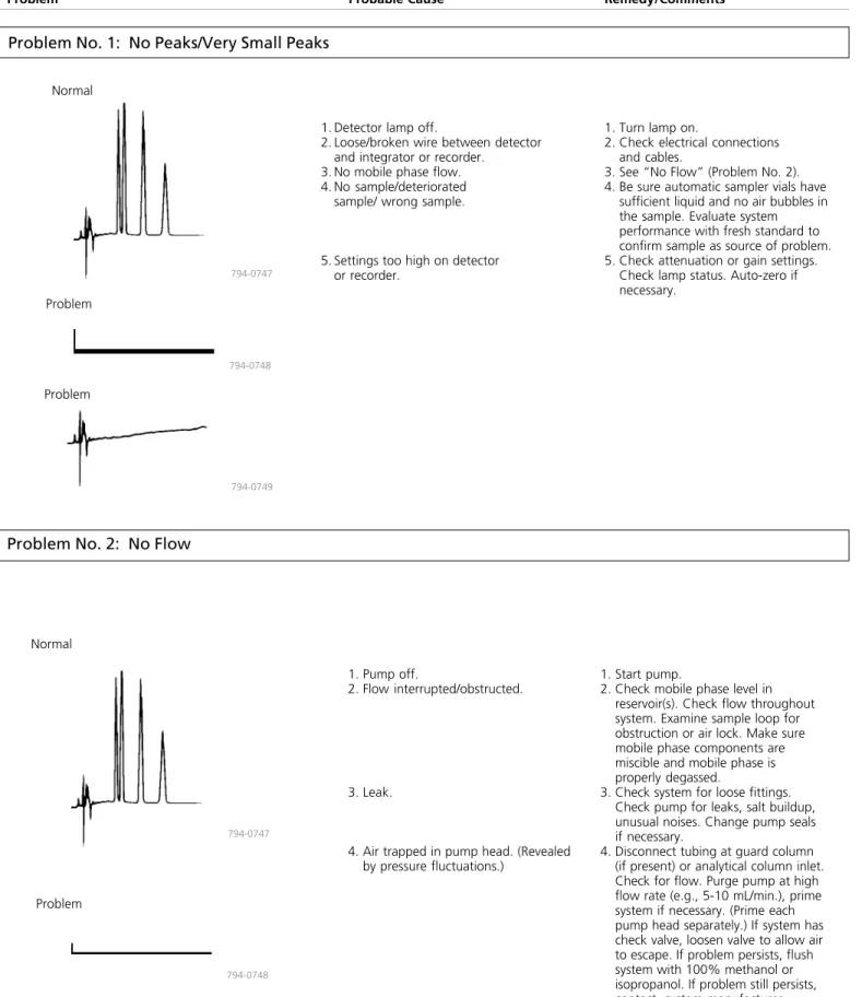
Problem No. 1: No Peaks/Very Small Peaks
Normal Normal 794-0748 794-0747 1. Pump off. 2. Flow interrupted/obstructed. 3. Leak.4. Air trapped in pump head. (Revealed by pressure fluctuations.)
1. Start pump.
2. Check mobile phase level in reservoir(s). Check flow throughout system. Examine sample loop for obstruction or air lock. Make sure mobile phase components are miscible and mobile phase is properly degassed.
3. Check system for loose fittings. Check pump for leaks, salt buildup, unusual noises. Change pump seals if necessary.
4. Disconnect tubing at guard column (if present) or analytical column inlet. Check for flow. Purge pump at high flow rate (e.g., 5-10 mL/min.), prime system if necessary. (Prime each pump head separately.) If system has check valve, loosen valve to allow air to escape. If problem persists, flush system with 100% methanol or isopropanol. If problem still persists, contact system manufacturer.
Problem No. 2: No Flow
794-0747 794-0748 794-0749 Problem Problem Problem
1. Detector lamp off.
2. Loose/broken wire between detector and integrator or recorder.
3. No mobile phase flow. 4. No sample/deteriorated
sample/ wrong sample.
5. Settings too high on detector or recorder.
1. Turn lamp on.
2. Check electrical connections and cables.
3. See “No Flow” (Problem No. 2). 4. Be sure automatic sampler vials have
sufficient liquid and no air bubbles in the sample. Evaluate system performance with fresh standard to confirm sample as source of problem. 5. Check attenuation or gain settings.
Check lamp status. Auto-zero if necessary.
Problem Normal
794-0751 794-0750
1. Leak.
2. Mobile phase flow interrupted/ obstructed.
3. Air trapped in pump head. (Revealed by pressure fluctuations.)
4. Leak at column inlet end fitting.
5. Air trapped elsewhere in system.
6. Worn pump seal causing leaks around pump head.
7. Faulty check valve. 8. Faulty pump seals.
1. Check system for loose fittings. Check pump for leaks, salt buildup, unusual noises. Change pump seals if necessary.
2. Check mobile phase level in reservoir(s). Check flow throughout system. Examine sample loop for obstruction or air lock. Make sure mobile phase components are miscible and mobile phase is properly degassed.
3. Disconnect tubing at guard column (if present) or analytical column inlet. Check for flow. Purge pump at high flow rate (e.g., 10 mL/min.), prime system if necessary. (Prime each pump head separately.) If system has check valve, loosen valve to allow air to escape.
4. Reconnect column and pump solvent at double the flow rate. If pressure is still low, check for leaks at inlet fitting or column end fitting.
5. Disconnect guard and analytical column and purge system. Recon-nect column(s). If problem persists, flush system with 100% methanol or isopropanol.
6. Replace seal. If problem persists, replace piston and seal. 7. Rebuild or replace valve. 8. Replace seals.
Problem No. 4: Pressure Higher Than Usual
794-0752 794-0750
Problem
Normal 1. Remove guard column and analyticalcolumn from system. Replace with
unions and 0.010'' I.D. or larger tubing to reconnect injector to detector. Run pump at 2-5 mL/ min. If pressure is minimal, see Cause 2. If not, isolate cause by systematically eliminating system components, starting with detector, then in-line filter, and working back to pump. Replace filter in pump if present. 2. Remove guard column (if present)
and check pressure. Replace guard column if necessary. If analytical column is obstructed, reverse and flush the column, while disconnected from the detector (page 14). If problem persists, column may be clogged with strongly retained contaminants. Use appropriate restoration procedure (Table 2, page 14). If problem still persists, change inlet frit (page 16) or replace column.
1. Problem in pump, injector, in-line filter, or tubing.
Problem No. 3: No Pressure/Pressure Lower Than Usual
2. Obstructed guard column or analytical column.
Problem Probable Cause Remedy/Comments
Problem No. 5: Variable Retention Times
1. Check system for loose fittings. Check pump for leaks, salt buildup, unusual noises. Change pump seals if necessary.
2. Check make-up of mobile phase. If mobile phase is machine mixed using proportioning values, hand mix and supply from one reservoir.
3. Purge air from pump head or check valves. Change pump seals if necessary. Be sure mobile phase is degassed.
4. Use reliable column oven. (Note: higher column temperatures increase column efficiency. For optimum results, heat eluant before introducing it onto column.) 5. Inject smaller volume (e.g., 10 μL vs.
100 μL) or inject the same volume after 1:10 or 1:100 dilutions of sample.
6. Adjust solvent. Whenever possible, inject samples in mobile phase. 7. Substitute new column of same type
to confirm column as cause. Discard old column if restoration procedures fail (see page 14).
1. Leak.
2. Change in mobile phase composition. (Small changes can lead to large changes in retention times.)
3. Air trapped in pump. (Retention times increase and decrease at random times.)
4. Column temperature fluctuations (especially evident in ion exchange systems).
5. Column overloading. (Retention times usually decrease as mass of solute injected on column exceeds column capacity.)
6. Sample solvent incompatible with mobile phase.
7. Column problem. (Not a common cause of erratic retention. As a column ages, retention times gradually decrease.) 794-0753 794-0747 Normal Problem Problem 794-0754
Problem No. 6: Loss of Resolution
Normal
794-0755
Problem
794-0756
1. Prepare fresh mobile phase (page 2).
2. Remove guard column (if present) and attempt analysis. Replace guard column if necessary. If analytical column is obstructed, reverse and flush (page 14). If problem persists, column may be clogged with strongly retained contaminants. Use appropriate restoration procedure (Table 2, page 14). If problem still persists, change inlet frit (page 16) or replace column.
1. Mobile phase contaminated/deterio-rated (causing retention times and/or selectivity to change).
Problem No. 7: Split Peaks
1. Remove guard column (if present) and attempt analysis. Replace guard column if necessary. If analytical column is obstructed, reverse and flush (page 14). If problem persists, column may be clogged with strongly retained contaminants. Use appropri-ate restoration procedure (Table 2, page 14). If problem still persists, inlet frit is probably (partially) plugged. Change frit (page 16) or replace column.
2. Replace frit (see above)
3. Repack top of column with pellicular particles of same bonded phase functionality. Continue using the column in reverse flow direction. 4. Adjust solvent. Whenever possible,
inject samples in mobile phase.
794-0757
Normal
Problem
Problem No. 8: Peaks Tail on Initial and Later Injections
NormalProblem
794-0759 794-0747
Problem No. 9: Tailing Peaks
Problem Normal
794-0747
794-0759
1. Remove guard column (if present) and attempt analysis. Replace guard column if necessary. If analytical column is source of problem, use appropriate restoration procedure (Table 2, page 14). If problem persists, replace column. 2. Check make-up of mobile phase
(page 2).
3. Check column performance with standards.
1. Guard or analytical column contamin-ated/worn out.
2. Mobile phase contaminated/ deteriorated.
3. Interfering components in sample.
1. First check column performance with standard column test mixture. If results for test mix are good, add ion pair reagent or competing base or acid modifier (page 2).
2. Adjust pH. For basic compounds, lower pH usually provides more symmetric peaks.
3. Try another column type (e.g., deactivated column for basic compounds).
4. See Problem No. 7.
5. Peaks can tail when sample is injected in stronger solvent than mobile phase. Dissolve sample in mobile phase.
2. Partially blocked frit.
3. Small (uneven) void at column inlet.
4. Sample solvent incompatible with mobile phase.
794-0758
1. Sample reacting with active sites.
4. Small (uneven) void at column inlet. 2. Wrong mobile phase pH.
3. Wrong column type.
5. Wrong injection solvent.
1. Contamination on guard or analytical column inlet.
Problem Probable Cause Remedy/Comments
Problem No. 10: Fronting Peaks
Problem No. 11: Rounded Peaks
794-0761 794-0760
794-0763 794-0762
Normal 1. Column overloaded.
2. Sample solvent incompatible with mobile phase.
3. Shoulder or gradual baseline rise before a main peak may be another sample component.
1. Inject smaller volume (e.g., 10 μL vs. 100 μL). Dilute the sample 1:10 or 1:100 fold in case of mass overload. 2. Adjust solvent. Whenever possible,
inject samples in mobile phase. Flush polar bonded phase column with 50 column volumes HPLC grade ethyl acetate at 2-3 times the standard flow rate, then with intermediate polarity solvent prior to analysis.
3. Increase efficiency or change selectivity of system to improve resolution. Try another column type if necessary (e.g., switch from nonpolar C18 to polar cyano phase).
Normal 1. Detector operating outside linear
dynamic range.
2. Recorder gain set too low. 3. Column overloaded.
4. Sample-column interaction.
5. Detector and/or recorder time constants are set too high.
1. Reduce sample volume and/or concentration.
2. Adjust gain.
3. Inject smaller volume (e.g., 10 μL vs. 100 μL) or 1:10 or 1:100 dilution of sample.
4. Change buffer strength, pH, or mobile phase composition. If necessary, raise column temperature or change column type. (Analysis of solute structure may help predict interaction.)
5. Reduce settings to lowest values or values at which no further improve-ments are seen.
Problem
Problem No. 12: Baseline Drift
Problem No. 13: Baseline Noise (regular)
1. Control column and mobile phase temperature, use heat exchanger before detector.
2. Use HPLC grade solvents, high purity salts, and additives. Degas mobile phase before use, sparge with helium during use. 3. Flush cell with methanol or other
strong solvent. If necessary, clean cell with 1N HNO3 (never with HCl and never use nitric acid with PEEK tubing or fittings.) 4. Unplug or replace line. Refer to
detector manual to replace window. 5. Correct composition/flow rate. To
avoid problem, routinely monitor composition and flow rate. 6. Flush column with intermediate
strength solvent, run 10-20 column volumes of new mobile phase through column before analysis. 7. Check make-up of mobile phase
(page 2).
8. Use guard column. If necessary, flush column with strong solvent between injections or periodically during analysis.
9. Change wavelength to UV absor-bance maximum.
1. Column temperature fluctuation. (Even small changes cause cyclic baseline rise and fall. Most often affects refractive index and conductivity detectors, UV detectors at high sensitivity or in indirect photometric mode.)
2. Nonhomogeneous mobile phase. (Drift usually to higher absorbance, rather than cyclic pattern from temperature fluctuation.)
3. Contaminant or air buildup in detector cell.
4. Plugged outlet line after detector. (High pressure cracks cell window, producing noisy baseline.) 5. Mobile phase mixing problem or
change in flow rate.
6. Slow column equilibration, especially when changing mobile phase. 7. Mobile phase contaminated,
dete-riorated, or not prepared from high quality chemicals.
8. Strongly retained materials in sample (high k’) can elute as very broad peaks and appear to be a rising baseline. (Gradient analyses can aggravate problem.)
9. Detector (UV) not set at absorbance maximum but at slope of curve.
794-0748
Normal
Problem
794-0764
1. Degas mobile phase. Flush system to remove air from detector cell or pump.
2. Incorporate pulse damper into system.
3. Mix mobile phase by hand or use less viscous solvent.
4. Reduce differential or add heat exchanger.
5. Isolate LC, detector, recorder to determine if source of problem is external. Correct as necessary. 6. Check system for loose fittings.
Check pump for leaks, salt buildup, unusual noises. Change pump seals if necessary.
1. Air in mobile phase, detector cell, or pump.
2. Pump pulsations.
3. Incomplete mobile phase mixing. 4. Temperature effect (column at high
temperature, detector unheated). 5. Other electronic equipment on same
line. 6. Leak. 794-0765 794-0748 Normal Problem
Problem Probable Cause Remedy/Comments
Problem No. 14: Baseline Noise (irregular)
Problem No. 15: Broad Peaks
1. Check system for loose fittings. Check pump for leaks, salt buildup, unusual noises. Change pump seals if necessary.
2. Check make-up of mobile phase. (page 2).
3. Isolate detector and recorder electronically. Refer to instruction manual to correct problem. 4. Flush system with strong solvent. 5. Purge detector. Install
back-pressure regulator after detector. Check the instrument manual, particularly for RI detectors (exces-sive backpressure can cause the flow cell to crack).
6. Clean cell. 7. Replace lamp.
8. Replace column and clean system. 1. Leak.
2. Mobile phase contaminated, deterio-rated, or prepared from low quality materials.
3. Detector/recorder electronics. 4. Air trapped in system. 5. Air bubbles in detector. Normal Problem 794-0748 794-0766 Normal Problem 794-0767 794-0768
1. Prepare new mobile phase. 2. Adjust flow rate.
3. Check system for loose fittings. Check pump for leaks, salt buildup, and unusual noises. Change pump seals if necessary.
4. Adjust settings.
5. a. Inject smaller volume (e.g., 10 μL vs. 100 μL) or 1:10 and 1:100 dilutions of sample.
b. Reduce response time or use smaller cell.
c. Use as short a piece of 0.007-0.010" I.D. tubing as practical.
d. Reduce response time. 6. Increase concentration. 7. Replace guard column.
8. Replace column with new one of same type. If new column does not provide narrow peaks, flush old column (Table 2, page 14), then retest.
9. Replace column or open inlet end and fill void (page 16).
10. Change column type to improve separation.
11. Increase temperature. Do not exceed 75 °C unless higher temperatures are acceptable to column manufacturer. 1. Mobile phase composition changed.
2. Mobile phase flow rate too low. 3. Leak (especially between column and
detector).
4. Detector settings incorrect. 5. Extra-column effects:
a. Column overloaded
b. Detector response time or cell volume too large.
c. Tubing between column and detector too long or I.D. too large. d. Recorder response time too high. 6. Buffer concentration too low. 6. Detector cell contaminated. (Even
small amounts of contaminants can cause noise.)
7. Weak detector lamp.
8. Column leaking silica or packing material.
7. Guard column contaminated/worn out. 8. Column contaminated/worn out.
9. Void at column inlet.
10. Peak represents two or more poorly resolved compounds.
Problem No. 16: Change in Peak Height (one or more peaks)
Problem No. 17: Change in Selectivity
Normal Problem 794-0770 794-0769 Normal 794-0771 794-0772 Problem1. Check make-up of mobile phase (page 2).
2. Confirm identity of column packing. For reproducible analyses, use same column type. Establish whether change took place gradu-ally. If so, bonded phase may have stripped. Column activity may have changed, or column may be contaminated.
3. Adjust solvent. Whenever possible, inject sample in mobile phase. 4. Adjust temperature. If needed, use
column oven to maintain constant temperature.
1. Use fresh sample or standard to confirm sample as source of problem. If some or all peaks are still smaller than expected, replace column. If new column improves analysis, try to restore the old column, following appropriate procedure (Table 2, page 14). If performance does not improve, discard old column. 2. Check system for loose fittings.
Check pump for leaks, salt buildup, unusual noises. Change pump seals if necessary.
3. Be sure samples are consistent. For fixed volume sample loop, use 2-3 times loop volume to ensure loop is completely filled. Be sure automatic sampler vials contain sufficient sample and no air bubbles. Check syringe-type injectors for air. In systems with wash or flushing step, be sure wash solution does not precipitate sample components. 4. Check settings.
5. Replace lamp. 6. Clean cell.
1. Increase or decrease solvent ionic strength, pH, or additive concentration (especially affects ionic solutes). 2. Column changed, new column has
different selectivity from that of old column.
3. Sample injected in incorrect solvent or excessive amount (100-200 μL) of strong solvent.
4. Column temperature change. 1. One or more sample components
deteriorated or column activity changed.
2. Leak, especially between injection port and column inlet. (Retention also would change.)
3. Inconsistent sample volume.
4. Detector or recorder setting changed. 5. Weak detector lamp.
Problem Probable Cause Remedy/Comments
Problem No. 18: Negative Peak(s)
Normal
794-0747
Problem
794-0773
Problem No. 19: Ghost Peak
1. Contamination in injector or column.
2. Late eluting peak (usually broad) present in sample.
1. Flush injector between analyses (a good routine practice). If necessary, run strong solvent through column to remove late eluters. Include final wash step in gradient analyses, to remove strongly retained compounds. 2. a. Check sample preparation.
b. Include (step) gradient to quickly elute component.
794-0774 794-0760
(solvent injected after sample)
794-0775
1. Check polarity.
2. Use mobile phase with lower refractive index, or reverse recorder leads.
3. Adjust or change sample solvent. Dilute sample in mobile phase whenever possible.
4. a. Change polarity when using indirect UV detection, or b. Change UV wavelength or use
mobile phase that does not adsorb chosen wavelength. 1. Recorder leads reversed.
2. Refractive index of solute less than that of mobile phase (RI detector). 3. Sample solvent and mobile phase
differ greatly in composition (vacancy peaks).
4. Mobile phase more absorptive than sample components to UV wavelength.
(solvent injected after sample)
Further Recommendations
We also suggest referring to the maintenance and troubleshooting sections of your instrument manual. Modern HPLC systems often have self-diagnostic capabilities that help isolate the problem area within the instrument. For persistent problems relating to the column or your particular analysis, please contact Supelco’s Technical Service Department.
selectivity (pages 14-15), suggestions on how to prevent and solve column hardware problems (page 16), and a selection of column protection products from the Supelco catalog. Please refer to our catalog for our complete line of accessories that prolong column life and, in general, simplify or improve your HPLC or FPLC® analysis. Finally, phone us to request additional literature about our HPLC
Previous Sample
Normal
Silica Column
Flush with the following: 1. 50 mL hexane 2. 50 mL methylene chloride 3. 50 mL 2-propanol 4. 50 mL methanol 5. 25 mL methylene chloride 6. 25 mL mobile phase
Evaluate column performance according to conditions specified by the manufacturer.
Note: See also the Silica Column Regeneration Solution listed on page 15 for rejuvenating a deactivated silica column.
Silica-Based Reversed Phase Column (alkyl●●●●●, phenyl, or diphenyl column, SUPELCOSIL LC-PAH column)
A. Water Soluble Samples Flush with the following:
1. Flush with warm (60 °C) distilled water 2. 50 mL methanol
3. 50 mL acetonitrile 4. 25 mL methanol 5. 25 mL mobile phase Evaluate column performance. B. Samples Not Soluble in Water
Flush with the following: 1. 50 mL 2-propanol 2. 50 mL methylene chloride 3. 50 mL hexane
4. 25 mL isopropanol 5. 25 mL mobile phase Evaluate column performance.
Silica-Based Ion Exchange Columns (strong or weak anion or cation exchange)
Most analyses involving ion exchange systems use ionic mobile phases. Compounds that may affect column performance are usually insoluble or only slightly soluble in water. The following procedure should be sufficient to remove these compounds.
Flush with the following:
1. 50 mL hot (40-60 °) distilled water 2. 50 mL methanol
3. 50 mL acetonitrile 4. 25 mL methylene chloride 5. 25 mL methanol 6. 25 mL mobile phase Evaluate column performance.
Silica-Based Columns for RPLC of Proteins and Peptides Follow the protocol for silica-based reversed phase columns. Alternatively, make one or more 100 μL injections of
trifluoroethanol (determine the number of injections by evaluating column performance after each injection).
Evaluate column performance. Polar-Bonded Phase Column
(amino, cyano, or diol column or Pirkle-type chiral columns). For a column used in the reversed phase mode
(e.g., organic solvent/aqueous buffer mobile phase), follow the same cleanup procedure as for silica-based reversed phase columns. For a column used with nonaqueous mobile phases, use the following scheme:
Flush with the following: 1. 50 mL chloroform 2. 50 mL methanol 3. 50 mL acetonitrile 4. 25 mL methylene chloride 5. 25 mL methanol 6. 25 mL mobile phase Evaluate column performance.
●C8, C18, etc.
The following procedures should rejuvenate a column whose performance has deteriorated due to sample contamination. Disconnect and reverse the column. Connect it to the pump, but not the detector. Follow the appropriate flushing procedure in this table, using a flow rate that results in column back pressure of 1500-4500 psi, but never higher than the maximum recommended pressure in the manufacturer’s instruction manual. If you have a SUPELCOSIL column, analyze with the test mix and the conditions listed on the data sheet. Efficiency, symmetry, and capacity should be within 10-15% of the test sheet values. If not, repack the column inlet (page 16) or replace the column.
Note: Volumes listed in Table 2 are for 25 cm x 4.6 mm I.D. columns, which have a column volume of 4.15 mL. When restoring a 4.6 mm I.D. column shorter or longer than 25 cm, multiply all volumes in Table 2 by the ratio of the column length to 25 (e.g., for a 15 cm column: 15/25, or 0.6 times the volumes in Table 2). When restoring a column of internal diameter other than 4.6 mm, multiply all volumes in Table 2 by the ratio of the square of the column I.D. to (4.6)2 (e.g., for a 3.2 mm I.D. column: (3.2)2/(4.6)2 = 10.24/21.16 = 0.48 times the values in Table 2).
SUPELCOSIL LC-PCN Column A. To Remove Protein
Flush with 10 column volumes of acetonitrile:water, 50:50, containing 0.1% trifluoroacetic acid.
B. To Remove TCA
Flush with 10 column volumes of distilled water (adjust pH to 2.5 with H3PO4), then with 10 column volumes each of:
1. water (to remove salts) 2. methanol (to remove water)
3. methanol/methylene chloride, 50:50 (a general clean-up solution)
4. methanol
If column performance still is not acceptable, prepare the mobile phase buffer at 10X the concentration used for the analysis and recycle through the column overnight.* Reequilibrate the column with mobile phase at the normal buffer concentration and reevaluate.
*Use caution: with some buffer types and/or concentrations a 10-fold increase in concentration can cause precipitation.
Table 3.
Properties of Organic Solvents Commonly Used in HPLC
Polarity
Miscible with Water? UV
Cutoff● Refractive Indexat 20 °C at 20 °C, cPViscosity
nonpolar no no no no no yes no yes poorly yes yes yes yes yes 200 200 263 245 235 215 215 330 260 215 190 210 205 –– 1.3750 1.3910 1.4595 1.4460 1.4240 1.4070 1.3530 1.3590 1.3720 1.4220 1.3440 1.3770 1.3290 1.3328 0.00 0.01 0.14 0.31 0.32 0.35 0.29 0.43 0.45 0.49 0.50 0.63 0.73 >0.73 0.33 0.50 0.97 0.57 0.44 0.55 0.23 0.32 0.45 1.54 0.37 2.30 0.60 1.00
C2 – Same Column Exposed to Water and Alcohol
Min 6 Min 794-0787, -0788, -0789 1 3
C1 – Properly Performing Column 2
3 2 1
1 2
C3 – Same Column Treated with Regeneration Solution
3 1. Benzene 2. Benzanilide 3. Acetanilide Solvent Solvent Strength, ∈o (silica) polar Hexane Isooctane Carbon tetrachloride Chloroform Methylene chloride Tetrahydrofuran Diethyl ether Acetone Ethyl acetate Dioxane Acetonitrile 2-Propanol Methanol Water ●Typical values
Column Test Mixes
Performance evaluation mixes for HPLC columns.
Well defined test mixes enable you to troubleshoot chromato-graphic problems, optimize system efficiency, and evaluate col-umns under conditions where their performance is understood. We ship our test mixes in amber ampuls to prevent photodegradation, and we include instructions for proper use and interpretation of results.
Choose from column-specific or application-specific mixes. Refer to our catalog for our extensive selection of test mixes, or call our Technical Service Department.
Nonbonded Silica Columns Exposed to Polar Solvent
Samples and mobile phases containing very strongly polar solvents, such as water or alcohols, can deactivate uncoated silica HPLC columns. This can drastically affect column performance, particu-larly solute retention and selectivity. (Figure C2). Even prolonged column flushing with a nonpolar solvent only partially restores column performance, while wasting chemicals.
A silica regeneration solution quickly and inexpensively restores silica column performance by removing trapped polar material. Pump the solution through the affected column for 10 minutes at a rate of 4 mL/minute, then flush with mobile phase for 10 minutes at a rate of 2 mL/minute. Evaluate column performance by using the test mixture for evaluating silica columns (Cat. No. 58281). Perfor-mance should be virtually the same as before the polar solvent was introduced (Figure C3).
Silica Column Regeneration Solution, 200 mL 33175
Figure C.
Regeneration Solution Restores
Silica Column Performance
column: SUPELCOSIL LC-Si, 15 cm x 4.6 mm I.D., 3 μm packing (58981) mobile phase: 50:50, methylene chloride:methanol:water, 99.4:0.5:0.1 (Fig.
C1) 2-propanol:water, (Fig. C2)
99.4:0.5:0.1, Silica Column Regeneration Solution, 4 mL/min. for 10 min., then methylene chloride:methanol:water, 2 mL/ min. for 10 min. (Fig. C3)
flow rate: 2 mL/min. temp.: ambient
det.: UV, 254 nm
injection: 10 μL (Fig. C3 obtained after equilibration).
6 4 2 0 2 0 Min 0 2 4
Column Packing Porous Frit 1/16" Nut 1/16" Ferrule 794-0785 isolated the column as the problem source, and other restorative procedures have failed, a void in the packing or a persistent obstruction on the inlet frit may exist.
As a last resort, open the inlet end of the column. Caution: opening the inlet end, and more so opening the outlet end, can permanently damage the packing bed. Before opening columns, consult the manufacturer’s literature. (Never open either end of a resin-filled column).
Use the following procedure to open a column.
1. Disconnect the column from the system. To prevent the packing from oozing out of the column, perform subsequent steps as quickly as possible.
2. Using a vise and wrench, or two wrenches, carefully remove the inlet end fitting (see Figure D). If the frit remains in the fitting, dislodge it by tapping the fitting on a hard surface. If the frit stays on the column, slide it off rather than lift it off. This will help preserve the integrity of the packing bed.
Modular columns may require a special tool (e.g., Cat. No. 55216), to remove the frit cap.
3. Examine the old frit. Compression of the frit against the stainless steel tubing will leave a ring around the edge on the column side of a properly seated frit. No ring can mean the ferrule is seated too near the tubing end. The resulting loose connection can leak silica or act as a mixing chamber. 4. Examine the packing bed. If it is depressed or fractured,
you need a new column. 5. Replace the frit.
6. Replace the end fitting. Screw it down fingertight, then tighten 1/4 turn with a wrench.
Preventing Leaks
Leaks are a common problem in HPLC analyses. To minimize leaks in your system, avoid interchanging hardware and fittings from different manufacturers. Incompatible fittings can be forced to fit initially, but the separation may show problems and repeated connections may eventually cause the fitting to leak. If interchang-ing is absolutely necessary, use appropriate adapters and check all connections for leaks before proceeding.
Highly concentrated salts (>0.2 M) and caustic mobile phases can reduce pump seal efficiency. The lifetime of injector rotor seals also depends on mobile phase conditions, particularly operation at high pH. In some cases, prolonged use of ion pair reagents has a lubricating effect on pump pistons that may produce small leaks at the seal. Some seals do not perform well with certain solvents. Before using a pump under adverse conditions, read the instrument manufacturer’s specifications. To replace seals, refer to the mainte-nance section of the pump manual.
Unclogging the Column Frit
A clogged column frit is another common HPLC problem. To minimize this problem from the start, use a precolumn filter and guard column.
To clean the inlet, first disconnect and reverse the column. Connect it to the pump (but not to the detector), and pump solvent through at twice the standard flow rate. About 5-10 column volumes of solvent should be sufficient to dislodge small amounts of particulate material on the inlet frit. Evaluate the performance of the cleaned column using a standard test mixture.
Replacing a Frit at the Column Inlet
Sometimes neither solvent flushing (see above) nor restoration procedures (see Table 2) restore a column’s performance. If you’ve
Column
Endfitting
B. Modular Column with Reusable Endfittings
794-0786
Figure D.
Typical HPLC Column Designs
A Selection of Column Protection Products
910-0113 250 mL ReservoirFiltration Apparatus 2
Cap 1000 mL Flask Clamp Funnel BaseProtect your instrument and columns by removing particles and gases from solvents and other mobile phase components. Nylon 66 membrane filters are compatible with all solvents commonly used in HPLC.
Description Cat. No.
Supelco Mobile Phase Filtration Apparatus
Filtration Apparatus 1 58061
Filtration Apparatus 2 58062-U
Replacement Glass Parts For Filtration Apparatus 1
Reservoir, 250 mL 58063
Reservoir, 500 mL 58074
Funnel Base and Stopper 58064
For Filtration Apparatus 2
Tapered Funnel Base 58068
Tapered Flask, 1000 mL for Apparatus 2 58070-U
Tapered Flask, 2000 mL for Apparatus 2 58075
Cap for Flask for Apparatus 2 58071
Replacement Filter Parts for Both Apparatus
Filter Holder and Screen, SS 58065
Gaskets, Teflon (pk. of 10) 58066
Filter, Nylon 66, 47 mm (pk. of 50)
0.45 μm pores 58067
0.20 μm pores 58060-U
Clamp, Spring Action 58053
Filtration Apparatus 1 (connects to 1000 mL sidearm flask) Includes 250 mL glass reservoir, funnel base and stopper, clamp, stainless steel holder and screen, 10 Teflon gaskets, 50 Nylon 66 filters (47 mm, 0.45 μm pores).
Filtration Apparatus 2 (connects to aspiration line) Includes 250 mL glass reservoir, 34/45 tapered funnel base, 34/45 tapered 1000 mL flask and glass cap, clamp, stainless steel holder and screen, 10 Teflon gaskets, 50 Nylon 66 filters (47 mm, 0.45 μm pores).
Supelco Mobile Phase Degassing System
●4 Channel●0-5 mL/min. Flow Range
●Validation output satisfies system compliance
●Smart sensor detects leaks and communicates with vacuum pump
●LED indicates degassing status ●Unprecedented 4 year warranty
The Supelco Mobile Phase Degassing system with its smart sensor not only detects and alerts you to leaks, it also communicates with the vacuum pump. If a change in vacuum is detected due to mobile phase flow rate changes, the pump can compensate by changing its speed. The validation output records vacuum level to satisfy system compliance and validation requirements. The degassing system has a Teflon® AF membrane, with NO-OX™ fittings and tubing.
Description Cat. No.
Supelco Mobile Phase Degassing System 55018-U
E000923
Supelco
™Mobile Phase Filtration Apparatus
(connect to aspiration line)A precolumn filter is essential for protecting HPLC columns against particulate matter which can accumulate on the column frit, leading to split peaks and high back pressure. Sources of particles include mobile phases (especially when buffers are mixed with organic solvents), pump and injector seals, and samples. Use a 2.0 μm frit to protect columns containing 5 μm or larger particles, or a 0.5 μm frit for columns with particles smaller than 5 μm.
SSI High Pressure Precolumn Filter
In-line installation. The 316 stainless steel filter disc (0.5 μm pores) is easily replaced without removing the column end fitting. Maxi-mum operating pressure: 15,000 psi (1054 kg/cm²). For 1/16" tubing.
Description Cat. No.
SSI High Pressure Precolumn Filter
10-32 Threads2 59269
Waters Threads 59271
Filter Elements and Seals (pk. of 10)
0.5 μm pores 59273
2 μm pores 59272
2Most HPLC fittings, except SSI and some Waters fittings, have 10-32 threads.
Description Cat. No.
Upchurch Precolumn Filter
0.5 μm frit 55079
2 μm frit 55078
Frits (pk. of 10)
0.5 μm 55080-U
2 μm 55081
Description Cat. No.
Isolation Technologies Precolumn Filter
with 3 mm frit (4.6 mm columns) 57675-U
with 1.5 mm frit (2.1 mm columns) 57676-U
Frits (pk. of 5)
3 mm 57677
1.5 mm 57678
Description Cat. No.
Valco Precolumn Filters
Frit Filter 58420-U
Screen Filter 58279-U
Frits (pk. of 10)
0.5 μm pores 59037
2.0 μm pores 59129
Screens (pk. of 10) 58284
3Frits and screens should not be interchanged in these filters.
Description Cat. No.
SSI High Pressure Preinjector Filter 59262-U
Replacement Filter Elements and Seals (pk. of 2)
0.5 μm pores 59264
2 μm pores 59265
2Most HPLC fittings, except SSI and some Waters fittings, have 10-32 threads.
P000551
Description Cat. No.
Supelco Precolumn Filter Z22732-3
Frits (pk. of 5) 0.5 μm pores Z29087-4 2 μm pore Z22733-1 PEEK/Teflon, 2 μm1 57430-U 1Biocompatible, metal-free.
Supelco Filter
Direct-connect; protects analytical and guard columns. Our precolumn filter can be connected directly, hand-tight, into any HPLC column or guard column listed in our current catalog, or with any other column that has Valco-compatible endfittings. PEEK cap and body, 2 μm stainless steel frit. For a metal-free system, order PEEK/Teflon replacement frits (Cat. No. 57430-U).
P000548
Place between the pump and injector to provide fi-nal filtration for the mo-bile phase. Easily replaced 316 stainless steel filter
element (0.5 μm pores). Maximum operating pressure: 15,000 psi (105MPa). For 1/16" O.D. tubing, 10-32 threads2.
SSI High Pressure
Preinjector Filter
P000547
Valco Precolumn Frit and
Screen Filters
3In-line installation. Efficient, low dead volume filters protect your columns from particles without reducing column per-formance. The replaceable 1/8" frit has 0.5 μm pores to
protect 3 μm or 5 μm column packings, the replaceable screen has 2 μm pores. Choose the frit filter for higher filtration capacity (most applications) or the screen filter for less dead volume (e.g., with microbore columns). Use with 1/16" O.D. tubing; 1/16" fittings included. P000550
Isolation
Technologies
Precolumn Filter
In-line installation. High capacity inletfil-ter minimizes dead volume and band broadening, to prevent loss of column efficiency while protecting your column. Frit porosity: 0.5 μm. Complete as shown.
P000549
Upchurch Precolumn Filter
In-line installation. Stainless steel body with inert polyetherether-ketone (PEEK) endfittings and a 0.5 μm or 2 μm PEEK frit in one2 3 4 5 1 6 From Pump To Column MBB Passage MBB Port From Loop To Loop
Rheodyne Model 7725 and 7725i Injectors
The Rheodyne Model 7725 injector allows you to inject 1 μL-5 mL samples with accuracy and precision. The rugged, easily maintained design offers many advanced features:
●Patented continuous flow design (see figure) – flow is uninterrupted when you switch from LOAD to INJECT ●Easy seal adjustment using pressure screw on front of injector
●Wide port angle (30 °), for easy access to fittings
Injector includes a 20 μL sample loop and is supplied with a VESPEL rotor seal that can be replaced with a Tefzel rotor seal for operation at pH 0-14. Factory set at 5000 psi (345 bar), adjustable to 7000 psi (483 bar). Model 7725i has an internal position sensing switch.
A Model 7725 Injector Reduces Wear
and Tear on Your Columns
Description Cat. No.Model 7725 Injector 57620-U
Model 7725i Injector 57621
Replacement Components
VESPEL Rotor Seal 58830-U
Tefzel Rotor Seal 57633
Stator Face Assembly 57634
Needle Port Cleaner 57635
Valve Angle Bracket
(for all metal Rheodyne valves) 57636
RheBuild Kit for 7725/7725i/7726 55049
Sample Loops (wide-angle ports; fittings included)
2 μL 57622 5 μL 57623 10 μL 57624 20 μL 57625 50 μL 57626 100 μL 57627 200 μL 57628-U 500 μL 57629-U 1 mL 57630 2 mL 57631 5 mL 57632
Note: Use VESPEL seals to pH 10, Tefzel seals to pH 14. Supelco is an authorized Rheodyne dealer.
A conventional HPLC valve momentarily interrupts flow during sample injection, subjecting your column to repetitive pressure shocks. Rheodyne’s patented MBB (make-before-break) design makes the new connection before breaking the old one, providing uninterrupted flow. 796-0423
Optimize
Technologies Pump
Replacement Parts
A preventative mainte-nance program that in-cludes routine replacement of pump parts that are sub-ject to wear will help youavoid costly downtime. Our extensive selection of Optimize Tech-nologies check valves, seals, and pistons meet or exceed pump manufacturers' specifications. For the most up-to-date selection of pump parts, refer to the current Supelco catalog, or call our Technical Service Department.
P000583
SSI LO-Pulse Damper
A pulse damper controls pump pulsations for a more stable baseline. The SSI LO-Pulse damper is a patented unit compatible with single piston reciprocating HPLC pumps (Altex 110A, Eldex pumps, LDC Mini-Pump VS, SSI Models 200 and 300, etc.). At pressures from 500 psi to 6000 psi (35-420 kg/cm²), it improves precision of quantitative analyses and detection limits for trace sample compo-nents. Fittings and instructions included.
Description Cat. No.
Pulse Damper 58455
995-0148, 897-0035
SRS-3000 SRS-1000
Recover and reuse clean mobile phase, dispose of only contaminated mobile phase.
●Reduce solvent purchase and disposal costs ●Save money, mobile phase preparation time,
and the environment
Supelco SRS-3000 and SRS-1000 Solvent Recovery Systems can save money and time in any isocratic analysis. A microprocessor-controlled solvent switching valve monitors detector output and directs the solvent to the waste reservoir only when a peak is detected. When the baseline falls below the threshold you select, the uncon-taminated solvent is directed back to the mobile phase reservoir. In a typical isocratic analysis, 80-90% of the mobile phase is uncontami-nated and can be recycled. Settings for threshold, detection range, and delay time enable you to precisely control the switching valve. In addition to the basic features mentioned above, the SRS-3000 unit offers validation output (included), an Autoclean option (see below), and storage for up to 10 method files. The validation output provides a continuous, auditable data trail of the solvent recycling valve position, for GMP, GLP, or ISO-9000 protocols. The valve position is recorded by superimposing tick marks over a separate copy of the chromatographic signal.
Autoclean Valve - The SRS-3000 system also is available with a valve that enables you to select a different solvent to flush the HPLC system. The Autoclean valve is especially useful if you are using a single pump with mobile phases containing buffer or other salts. The Autoclean valve installs between the mobile phase reservoir and the pump. It has two inlet lines, one for the mobile phase and one for the wash solvent. The valve can be factory installed, or you can order it separately and install it yourself.
Economy-Priced Unit - The economically priced SRS-1000 includes the same solvent-saving features as the SRS-3000 unit. A simpler display and no advanced features (no validation output, Autoclean option, or method storage memory) allow us to keep the price substantially lower. Both Systems are Ready to Use - Both systems include a control unit with switching valve, a power cord, a 2-lead signal cable (+/–), Teflon tubing and fittings, and an instruction manual. In addition to these components, the SRS-3000 system with the Autoclean valve has the wash valve, additional tubing and fittings, a wash start cable, and a pump remote stop cable.
The SRS-3000 and SRS-1000 units meet all CE requirements. The SRS-1000 units also meet UL and CSA requirements.
Autoclean Valve (option with SRS-3000) Flush Solvent Mobile Phase Reservoir Pump Injector Column Data System Detector Valve in SRS-3000/ SRS-1000 Recycle Waste Waste Reservoir SRS 3000 or SRS-1000 Solvent Recovery System
1. Connect SRS-3000 or SRS-1000 unit to detector signal output (cable is included). 2. Connect SRS-3000 or SRS-1000 unit to mobile phase and waste reservoirs and
detector (Teflon tubing is included).
3. Set the threshold value and begin saving time and money.
795-0506 1. Uracil 2. Phenol 3. Benzaldehyde 4. N,N-Diethyl-m-toluamide 5. Toluene 6. Ethylbenzene Solvent Recycled Solvent to Waste Threshold 0 1 2 3 4 5 6 Min 1 2 3 4 5 6
Recover 80% or More of the Mobile Phase
Used In an Isocratic Analysis
713-0516
Description Cat. No.
SRS-3000 Solvent Recovery System1 57431
SRS-3000 System with Autoclean1 57432
Switching valve assembly for SRS-3000 unit 57435 SRS-1000 Solvent Recovery System1
110 VAC 506125
220 VAC 506133
1CE approved.
Accelerating Customers’ Success through Innovation and
Leadership in Life Science,
High Technology and Service World Headquarters
3050 Spruce St., St. Louis, MO 63103 (314) 771-5765
sigma-aldrich.com
Order/Customer Service (800) 325-3010 • Fax (800) 325-5052
Technical Service (800) 325-5832 • sigma-aldrich.com/techservice
Development/Custom Manufacturing Inquiries (800) 244-1173
©2009 Sigma-Aldrich Co. All rights reserved. SIGMA, , SAFC, , SIGMA-ALDRICH, ALDRICH, , FLUKA, , and SUPELCO, are trademarks belonging to Sigma-Aldrich Co. and its affiliate Sigma-Aldrich Biotechnology, L.P. Sigma brand products are sold through Sigma-Aldrich, Inc. Sigma-Aldrich, Inc. warrants that its products conform to the information contained in this and other Sigma-Aldrich publications. Purchaser must determine the suitability of the product(s) for their particular use. Additional terms and conditions may apply. Please see reverse side of the invoice or packing slip.