A Tag - Reader Authentication Scheme
for RFID Systems
Hakim Singh
(Roll No: 213CS2173)
Department of Computer Science and Engineering
National Institute of Technology, Rourkela
Rourkela-769 008, Odisha, India
A Tag - Reader Authentication Scheme
for RFID Systems
Thesis submitted in partial fulfillment of the requirements for the degree of
Master of Technology
inInformation Security
byHakim Singh
(Roll No: 213CS2173)under the guidance of
Dr. Ashok Kumar Turuk
Department of Computer Science and Engineering
National Institute of Technology, Rourkela
Rourkela-769 008, Odisha, India
Department of Computer Science and Engineering
National Institute of Technology Rourkela
Rourkela-769 008, Odisha, India.
Certificate
This is to certify that the work in the thesis entitled ”A Tag-Reader Authentication Scheme for RFID Systems ” submitted byHakim Singh is a record of an original re-search work carried out by him under our supervision and guidance in partial fulfillment of the requirements for the award of the degree of Master of Technology in Computer Science and Engineering, National Institute of Technology, Rourkela. Neither this thesis nor any part of it has been submitted for any degree or academic award elsewhere.
Dr.Ashok Kumar Turuk
Assistant Professor Department of CSE Place: NIT,Rourkela-769008 National Institute of Technology
Acknowledgment
First of all, I would like to express my deep sense of respect and gratitude towards my supervisor Prof Ashok Kumar Turuk, who has been the guiding force behind this work. I want to thank him for introducing me to the field of RFID Systems and giving me the opportunity to work under him. His undivided faith in this topic and ability to bring out the best of analytical and practical skills in people has been invaluable in tough periods. Without his invaluable advice and assistance it would not have been possible for me to complete this thesis. I am greatly indebted to him for his constant encouragement and invaluable advice in every aspect of my academic life. I consider it my good fortune to have got an opportunity to work with such a wonderful person.
I wish to thank all faculty members and secretarial staff of the CSE Department for their sympathetic cooperation.
During my studies at N.I.T. Rourkela, I made many friends. I would like to thank them all, for all the great moments I had with them.
When I look back at my accomplishments in life, I can see a clear trace of my family’s concerns and devotion everywhere. My dearest mother, whom I owe everything I have achieved and whatever I have become; my beloved father, for always believing in me and inspiring me to dream big even at the toughest moments of my life; and my brother and sister; who were always my silent support during all the hardships of this endeavor and beyond.
Abstract
Radio frequency Identification(RFID) system is latest a technology. It has been used in various application in the world. Radio frequency identification(RFID) can be used in supply chain management, automated payment systems and other daily application as essential technology to enhance lives of human beings. RFID systems are vulnerable for many malicious attacks against privacy and security. To solve these problems, many authentication protocols based on cryptography scheme have been developed in order to ensure preservation of privacy. However, many of the these approaches cannot fully pro-tect privacy in the presence of malicious readers or insider attacks. Our research work in thesis mainly focuses on designing secure RFID authentication schemes with untrace-ability. We observe a number of recent proposed RFID authentication scheme as well as related. Cryptography techniques, and then define the security and privacy require-ment for our RFID systems. Our main contribution in this thesis consist proposed RFID authentication.
Generally, the weakness of RFID technology is authentication systems between a reader and a tag become weak. In this thesis, we introduced RFID tag - reader authentica-tion scheme for use under the electronic product code global frame work . Which is more efficient for possible privacy and security threats in RFID system. This scheme is based on 16-bit random number. Random number is generated by 16-bit linear feedback shift register(LFSR). 16-bit Linear feedback shift register(LFSR) is based on polynomial feed-backX16+X14+X13+X11+1. We further analysed the RFID system’s security strength against various attacking scenarios, such that man in middle attack, eavesdropping, replay attack and mutual authentication.
Contents
Certificate i
Acknowledgment ii
Abstracst iii
List of Figures vi
List of Tables vii
List of Acronyms viii
1 Introduction 2 1.1 RFID Technology . . . 2 1.1.1 RFID Tags . . . 3 1.1.2 RFID Readers . . . 6 1.2 RFID Applications . . . 7 1.3 Motivation . . . 9 1.4 Objectives of Research . . . 9 1.5 Organisation of Thesis . . . 10 2 Literature Survey 12 3 Authentication Scheme 15 3.1 EPC class-1 generation-2 standard . . . 15
3.2 Authentication using Diffie Hellman Algorithm . . . 15
3.3 Proposed Authentication Scheme . . . 18
3.3.1 Proposed Scheme . . . 18
3.3.2 Reader Operation . . . 19
3.3.3 Tag Operation . . . 22
CONTENTS CONTENTS
4 Simulation & Results 26
4.1 Simulation and Implementation . . . 26 4.2 Security Analysis . . . 34
5 Conclusion and Future Work 36
Bibliography 37
Dissemination 40
List of Figures
1.1 RFID Systems Components . . . 3
1.2 RFID Passive and Active Tag Process . . . 6
3.1 Authentication Approach Proposed by EPC Global . . . 16
3.2 Authentication Approach Proposed by EPC Global . . . 16
3.3 Authentication using Diffie Hellman Algorithm . . . 17
3.4 Authentication using Diffie Hellman Algorithm . . . 17
3.5 Proposed RFID Authentication Scheme . . . 19
3.6 Proposed RFID Authentication Scheme . . . 20
3.7 Reader Operation . . . 21
3.8 Tag Operation . . . 23
3.9 16-bit Linear Feedback Shift Register with Maximum Length Feedback PolynomialX16+X14+X13+X11+1 . . . 24
List of Tables
4.1 RNR1 generate by Reader . . . 28
4.2 EPWDLR compute by Reader . . . 28
4.3 RNT1 generate by Tag . . . 29
4.4 EPWDLR compute by Tag . . . 30
4.5 Reader Authentication . . . 30
4.6 RNT2 generate by Tag . . . 31
4.7 EPWDMT compute by Tag . . . 31
4.8 RNR2 generate by Reader . . . 32
4.9 EPWDLR compute by Tag . . . 33
4.10 Tag Authentication . . . 33
4.11 Comparison between Existing Scheme and Proposed Scheme . . . 34
List of Acronyms
Acronym Description
R Reader
T Tag
RR Reader Request
RFID Radio Frequency Identification EPC Electronic Product Code LFSR Linear Feedback Shift Register SV Seed Value
RNR1 Random Number Reader First RNT1 Random Number Tag First PWDL Password Lower Bits
PWDM Password Most Significant Bits RNT2 Random Number Tag Second RNR2 Random Number Reader second EPWDLT Encrypted Password Lower Bits Tag
EPWDMT Encrypted Password Most Significant Bits Tag EPWDLR Encrypted Password Lower Bits Reader
Chapter 1
Introduction
RFID Technology
RFID Application
Motivation
Objective of Research
Organization of Thesis
Chapter 1
Introduction
In This chapter describes the overview of the thesis. Part 1.1 describes the background of RFID technology and part 1.2 describes the application of RFID technology. Part 1.3 explains the research issues in RFID sysetms and describes the motivation of my research in part 1.4. The contribution of this thesis gives in part 1.5, and describes the organisation of the thesis in part 1.6.
1.1
RFID Technology
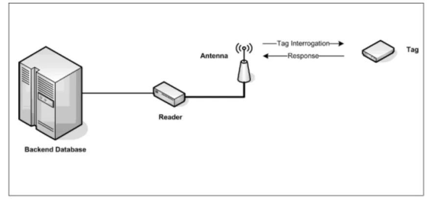
RFID systems is new technology. It is used in identify and track objects automatically through radio waves. It has been considered as a replacement of barcode and given some attractive features (12) (13). RFID systems have three main parts : reader, tags and back-end server. It is called as transponders. Transmitter or receiver is part of a transponder. That is contemplated to gets a needed radio signal and automatically send a response. In its easier implementing, the transponder listens via a radio beacon, and transmits a beacon of its itself as a response. As active tags do not hold to respond on being powered through the reader, active tag are not limited to operating inside the near field. Active tag can be interrogated and reply at forward distances away by the reader, its means that active tags (at a minimum) are able to sending and taking over larger distances Semi-passive tags hold a battery to power the memory circuitry, but depend on the near Field for power the radio circuits during the getting and transmitting of data. As active tags do not hold to respond on being powered through the reader, active tag are not limited to operating inside the near field. Passive tag is called as dead tag. Because passive tag do not have battery. Passive tag have only EPC, 32-bit password and common random number procedure. Battery or other power sources does not in RFID passive tags. In order to passive tags for work, the
1.1. RFID TECHNOLOGY CHAPTER 1. INTRODUCTION
antenna and the tag must be near impendency for the reader, as the tags keep an interior power source, and derive itself power to send by coupling for the near field of the antenna. So, passive tags must waiting to a signal by a reader. Getting power by the reader device is completed by an electromagnetic properties . Passive Tag do not keep internal power source, such as batteries. So, they are cheap and small. The microchip inside the tag is able to get power from the reader’s interrogation radio signals. All are shown in figure 1.1 (20).
Figure 1.1: RFID Systems Components
1.1.1
RFID Tags
Class of radio devices have units of RFID. It is called as transponders. Transmitter or receiver is part of a transponder. That is contemplated to gets a needed radio signal and automatically send a response. In its easier implementing, the transponder listens via a radio beacon, and transmits a beacon of its itself as a response. The transponder listen signal by beacon and after send by beacon of its self. Very difficult process may send a one alphabets or numbers back through the sources, or transmit many characters of numbers and letters. Lastly, blooming process can do a compute or checking system and combined encrypted radio broadcasting to finished eavesdroppers via finding the information being sending class of radio devices have units of RFID. It is called as transponders. Transmitter or receiver is part of a transponder. That is contemplated to gets a needed radio signal and automatically send a response. In its easier implementing, the transponder listens via a radio beacon, and transmits a beacon of its itself as a response. As active tags do not hold to respond on being powered through the reader, active tag are not limited to operating inside the near field. Active tag can be interrogated and reply at forward distances away
1.1. RFID TECHNOLOGY CHAPTER 1. INTRODUCTION
by the reader, its means that active tags (at a minimum) are able to sending and taking over larger distances Semi-passive tags hold a battery to power the memory circuitry, but depend on the near field for power the radio circuits during the getting and transmitting of data. As active tags do not hold to respond on being powered through the reader, active tag are not limited to operating inside the near field.Passive tag is called as dead tag. Because passive tag do not have battery. Passive tag have only EPC, 32-bit password and common random number procedure. Battery or other power sources does not in RFID passive tags. In order to passive tags for work, the antenna and the tag must be near independency for the reader, as the tags keep an interior power source, and derive itself power to send by coupling for the near field of the antenna. So, passive tags must waiting to a signal by a reader. Getting power by the reader device is completed by an electromagnetic properties. Passive tag do not keep internal power source, such as batteries. So, they are cheap and small.The microchip inside the tag is able to get power from the reader’s interrogation radio signals. A communication session can only be initiated by a reader range between a passive tag and a reader is limited. It called as the near field. While the name implies, the device must be comparatively near the reader in order for work. The near field in brief supplies sufficient power to the tag because it can transmits a reply(15) (17).
•Firstoneisencoding/decodingcircuitry
•Secondoneismemory
•T hirdoneisantenna
•Lastispowersupplycommunicationsprocess
Passive Tag
Passive tag is called as dead tag. Because passive tag do not have battery. Passive tag have only EPC, 32-bit password and common random number procedure. Battery or other power sources does not in RFID passive tags. In order to passive tags for work, the antenna and the tag must be near impendency for the reader, as the tags keep an interior power source, and derive itself power to send by coupling for the near field of the antenna. So, passive tags must waiting to a signal by a reader. The tag hold a echoic circuit competent of tempting power via the reader’s antenna. Getting power by the reader device is completed by an electromagnetic properties . Passive tag do not keep internal power
1.1. RFID TECHNOLOGY CHAPTER 1. INTRODUCTION
source, such as batteries. So, they are cheap and small. The microchip inside the tag is able to get power from the reader’s interrogation radio signals. A communication session can only be initiated by a reader range between a passive tag and a reader is limited. It called as the near field. While the name implies, the device must be comparatively near the reader in order for work. The near field in brief supplies sufficient power to the tag because it can transmits a reply (6) (16).
In order to passive tags for work, the antenna and the tag must be near impendency for the reader, as the tags keep an interior power source, and derive itself power to send by coupling for the near field of the antenna. The near field gets benefits of electromagnetic cretic and generates a small, less-lived electrical pulse with the passive tag that can power a tag large enough for it to reply.
passive tag do not keep internal power source, such as batteries. So, they are cheap and small. The microchip inside the tag is able to get power from the reader’s interrogation radio signals. A communication session can only be initiated by a reader range between a passive tag and a reader is limited (19) (20).
Semi-passive tag and Active Tag
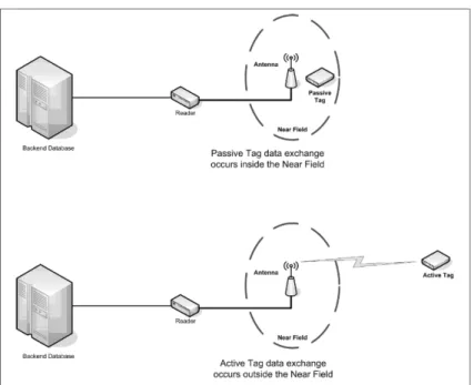
The successively for a passive tag is an active tag. Active tags keep their itself power source, commonly an interior battery. So, active tag hold a battery for power the radio circuitry, active tag can actively send and gets on their itself, without hold to be powered through the near field of the reader’s antenna . As active tags do not hold to respond on being powered through the reader, active tag are not limited to operating inside the near field. Active tag can be interrogated and reply at forward distances away by the reader, its means that active tags (at a minimum) are able to sending and taking over larger distances Semi-passive tags hold a battery to power the memory circuitry, but depend on the near field for power the radio circuits during the getting and transmitting of data. As active tags do not hold to respond on being powered through the reader, active tag are not limited to operating inside the near field. Passive tag is called as dead tag. Because passive tag do not have battery. Passive tag have only EPC, 32-bit password and common random number procedure. Battery or other power sources does not in RFID passive tags. In order to passive tags for work, the antenna and the tag must be near impendency for the reader,
1.1. RFID TECHNOLOGY CHAPTER 1. INTRODUCTION
as the tags keep an interior power source, and derive itself power to send by coupling for the near field of the antenna. So, passive tags must waiting to a signal by a reader. Getting power by the reader device is completed by an electromagnetic properties . Passive tag do not keep internal power source, such as batteries. So, they are cheap and small. The microchip inside the tag is able to get power from the reader’s interrogation radio signals. A communication session can only be initiated by a reader range between a passive tag and a reader is limited. It called as the near field. While the name implies, the device must be comparatively near the reader in order for work. The near field in brief supplies sufficient power to the tag because it can transmits a reply(1) (14).
Figure 1.2: RFID Passive and Active Tag Process
1.1.2
RFID Readers
The second component of RFID system is reader. Reader is read the information from the tags and then store in server or database. Reader is depends on distance because when distance is large then we are used high frequency reader and while distance is sort then we are used low frequency reader. As active tags do not hold to respond on being powered through the reader, active tag are not limited to operating inside the near field. Active tag can be interrogated and reply at forward distances away by the reader, its means that active tags (at a minimum) are able to sending and taking over larger distances Semi-passive tags hold a battery to power the memory circuitry, but depend on the near field
1.2. RFID APPLICATIONS CHAPTER 1. INTRODUCTION
for power the radio circuits during the getting and transmitting of data. As active tags do not hold to respond on being powered through the reader, active tag are not limited to operating inside the near field. Passive tag is called as dead tag. Because passive tag do not have battery. Passive tag have only EPC, 32-bit password and common random number procedure. Battery or other power sources does not in RFID passive tags. In order to passive tags for work, the antenna and the tag must be near impendency for the reader, as the tags keep an interior power source, and derive itself power to send by coupling for the Near Field of the antenna. So, Passive tags must waiting to a signal by a reader. Getting power by the reader device is completed by an electromagnetic properties . Passive tag do not keep internal power source, such as batteries. So they are cheap and small. The microchip inside the tag is able to get power from the reader’s interrogation radio signals. A communication session can only be initiated by a reader range between a passive tag and a reader is limited. It called as the Near Field. While the name implies, the device must be comparatively near the reader in order for work. The near field in brief supplies sufficient power to the tag because it can transmits a reply.
1.2
RFID Applications
Beginning from the 90s, RFID technology has launched in a variety of commercial prod-ucts. For example, Wal-Mart has started to require their suppliers to adopt RFID technol-ogy in their own smart cards after year 2000. This initiative has been the biggest push for commercial usage of this technology in the recent years. Beside, the massive com-mercial adoption in the marketplace, such technology has also been applied in military in the United States. In the following section, we presented some common applications for RFID tags and highlighting their security concerns. RFID tags can also store personal in-formation for security check-ins. Another common RFID application is the RFID-enabled vehicle immobilizer in the auto- motive industry. There is an embedded chip in each key that sends out out an 32-bit encrypted radio-frequency signal forming a particular code. With this code, the driver is able to start the car and activate the fuel pump with ease. As a result, this technology has increased anti-theft capability in the automotive industry. For example, an employee carries an ID card, embedded with a RFID chip, could authenticate
1.2. RFID APPLICATIONS CHAPTER 1. INTRODUCTION
his or her identity at the security entry in a facility within a very short period of time. The embedded chips in the new passports store the same personal information as those in the old printed document, including names, nationalities, sex, dates of birth, places of birth, ngerprints, and photos of the passport holders.
1. For instance, pharmaceutical industries in the United States, capturing ten percent of the global market, makes 32 billion dollars. The recent increase of counterfeit or diluted drugs has caught the attention of Food and Drug Administration (FDA). FDA considered this as a threat to public health. Implementation of the RFID technology could immediately improve pharmaceutical supply chain safety through real-time, oine, and item-level authentication, from the initial point of manufacturing to the nal stage of dispensing drugs to consumers in the pharmacies.This touch-free payment system speeds up transactions, when customers only need to place their credit cards in close proximity to an RFID reader. (7).
2. Many RFID-based payment systems are widely used in our daily life, including RFID- capable credit cards from major credit card association and companies and pay-ment cards in mass transit systems. This touch-free paypay-ment system speeds up transac-tions, when customers only need to place their credit cards in close proximity to an RFID reader. RFID tags can also store personal information for security check-ins. For exam-ple, an employee carries an ID card, embedded with a RFID chip, could authenticate his or her identity at the security entry in a facility within a very short period of time. The embedded chips in the new passports store the same personal information as those in the old printed document, including names, nationalities, sex, dates of birth, places of birth, ngerprints, and photos of the passport holders.
3. Another common RFID application is the RFID-enabled vehicle immobilizer in the auto- motive industry. There is an embedded chip in each key that sends out out an 32-bit encrypted radio-frequency signal forming a particular code. With this code, the driver is able to start the car and activate the fuel pump with ease. As a result, this technology has increased anti-theft capability in the automotive industry.
4. RFID tags can also store personal information for security check-ins. For example, an employee carries an ID card, embedded with a RFID chip, could authenticate his or her
1.3. MOTIVATION CHAPTER 1. INTRODUCTION
identity at the security entry in a facility within a very short period of time. The embedded chips in the new passports store the same personal information as those in the old printed document, including names, nationalities, sex, dates of birth, places of birth, ngerprints, and photos of the passport holders (4) (6) (8).
1.3
Motivation
To address all these objective mentioned below,The research should concern many prop-erties about RFID security and privacy.
Tag authentication is called a tag prove its validity for a reader, while reader authen-tication is in the opposite way. Mutual authenauthen-tication is used for tag and reader authenti-cation. In especially, tag authentication is more important because tags are very easier to counterfeit than readers. Authentication is an more effective approach to prevent attacks. Untraceability means that a tag is both anonymous and indistinguishable to an adver-sary. Although an RFID tag is vulnerable to compromise, an malicious reader should not identify the communication records of this tag in the past or future session. Thus,a protocol should not leak the identity or internal secret of RFID tags in communication processes.
Performance requirements should be satisfied. Considering the limited storage and computational ability of low-cost tags, cryptographic techniques used in the schemes should be basic and restricted. Besides, a back-end server may deal with a plenty of tags in one RFID system in real world scenarios. Thus,an RFID scheme should also be scalable and especially easy for a server to search the information of a tag in the database for these issues, the thesis focuses on designing secure and untraceable authentication schemes for RFID systems.
1.4
Objectives of Research
The weakness of RFID systems technology, it is high cost. Mutual authentication between a tag and a reader is less.
• To provide more security between reader and tag. • To prevention Man-in-the-middle attack.
1.5. ORGANISATION OF THESIS CHAPTER 1. INTRODUCTION
• To prevention Mutual Authentication.
1.5
Organisation of Thesis
The rest of Thesis is organized as follow:
Chapter 2: In this chapter A survey of Tag-reader authentication for RFID systems as reported in the literature is mentioned.
Chapter 3:In this chapter we have shown Proposed authentication scheme and Exist-ing Authentication scheme.
Chapter 4:In this chapter we have shown simulation result and implementation.
Chapter 2
Chapter 2
Literature Survey
Konidala et at. (1) proposed a scheme which is taken large time to mutual authenti-cation.Which is more secure than other scheme.It is not implemented in hardware.It is process completely depend kill passwords and access password.
However, due to the wireless nature of communication in RFID, identity theft can be achieve more easily without proper security measurement. Personal information is ex-posed for hackers, who would break into the devices, snap personal information, and then walk away with it. Unauthorized duplication of passports not only jeopardizes millions of Americans privacy, it also threatens national security (13).
Peris-Lopez et al. (2) required a Mix Bits function,which need more iterations to complete. This scheme is take more time for authentication between tag’s and reader.
In addition, many public transportation systems are also RFID-ready in major cities around the world, such as Massachusetts Bay Transportation Authority system in Boston, the Easy Card for Taipei Metro system, and Octopus Card in Hong Kong. The adoption of the RFID technology in these markets has made the mass transit systems transforming from a slow cash collection process to a speedy fare scan-and-go process. Vending ma-chines or many marketplaces in the cities can dispense the transit cards providing riders convenient sale methods and locations.
Li et al. (10) proposed a EX-OR approach for an fast implementation of protocol. It is take less time in computation to EX-OR operation. And this scheme is completely depend on EX-OR and random number.
Schulte et al. (14) This scheme is completely based on truncated multipliers. Trun-cated multiplier is take less time for authentication between tags and reader.
CHAPTER 2. LITERATURE SURVEY
secure than konidala approach because some modification in the previous approach. Ko and and Hsiao. (13) proposed an efficient array based truncated multiplier. This scheme is implemented in hardware. This is take less time other approach.
Active tags and passive tags hold batteries. The difference both of them is that. Active tags are able to power their memory circuitry and radio circuits. Semi passive tags still need the reader’s radio-frequency signals to power their radio circuits. So, Both contain their itself power source. Both of them can communicate with reader in a larger distance compared to passive tags.
Chapter 3
Authentication Scheme
EPC class-1 generation-2 standard
Authentication using Diffie Hellman Algorithm
Proposed Authentication Scheme
Reader Operation
Tag Operation
Chapter 3
Authentication Scheme
3.1
EPC class-1 generation-2 standard
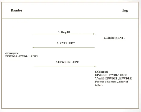
32-bit secure password is kept in the tag’s reserved memory if this password is true, then data transmit will be build between tag and reader. Firstly reader send a requests to tag. Tag is created a random number after transmit for reader.The reader computes encrypted password using performing a bit wise exclusive-or between actual password and random number. The encrypted password is send for the tag. The tag calculates encrypted password using performing a bit wise exclusive-or between actual password and random number. The encrypted password using performing a bit wise EX-OR of the gets encrypted password with the original as shown in Fig.3.1 and Fig.3.2. In this approach , both random number transmit in unencrypted form. Man in middle attack is possible to happen by takes exclusive-or operation between the encrypted passwords and random number, that gives actual password and their via unauthorized reader get the tags data. 32-bit secure password is kept in the tag’s reserved memory if this password is true, then data transmit will be build between tag and reader. Firstly reader send a requests to tag. Tag is created a random number after transmit for reader.The reader computes encrypted password using performing a bit wise exclusive-or between actual password and random number. The encrypted password is send for the tag.(10).
3.2
Authentication using Diffie Hellman Algorithm
Fig.3.3 and Fig.3.4 explain the proposed scheme communication step between a tag and a reader and the detailed classification of the proposed scheme is as follow.
Step 1: Firstly, reader send a request data for tag.
Step 2: The tag compute the value of R1 by P, Q and PWDL. 15
3.2. AUTHENTICATION USING DIFFIE HELLMAN ALGORITHMCHAPTER 3. AUTHENTICATION SCHEME
Figure 3.1: Authentication Approach Proposed by EPC Global
Figure 3.2: Authentication Approach Proposed by EPC Global
Step 3: The tag responds by generating R1 and EPC.
Step 4: EPC and R1 information is send for the server by the reader. Step 5: The server compute the value of R2 by P, Q and PWDL.
3.2. AUTHENTICATION USING DIFFIE HELLMAN ALGORITHMCHAPTER 3. AUTHENTICATION SCHEME
else communication is finished.
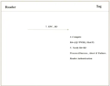
Step 7: The server calculate the value of R3 by P, Q and PWDM. Step 8: The server responds by R3 and EPC to reader.
Step 9: The reader responds by R3 and EPC to tag.
Step 10: The tag compute the value of R4 by P, Q and PWDM.
Step 11: Checking of R4=R3 is done. If it is true the process continues else commu-nication is finished.
Figure 3.3: Authentication using Diffie Hellman Algorithm
Figure 3.4: Authentication using Diffie Hellman Algorithm
3.3. PROPOSED AUTHENTICATION SCHEMECHAPTER 3. AUTHENTICATION SCHEME
3.3
Proposed Authentication Scheme
3.3.1
Proposed Scheme
There are three main component of proposed scheme. First is tag and Second is reader and third one is database or server. In the proposed scheme, each tag have an unique Electronic Product Code(EPC), Password(PWD) and Linear Feedback Shift Register(LFSR) given by manufacturer to encrypted Password(PWD). The database hold the information about Electronic Product Code(EPC) and Password(PWD) for all tags. It also keep a same protocol architecture. It is given in all tags (5) (12).
Fig.3.5 and Fig.3.6 shown the proposed scheme communication step between a reader and a tag and the detailed classification of the proposed scheme is as follow.
Step 1: Firstly, Reader transmits a request message for Tag.
Step 2: Tag transmits the response to reader with EPC and Seed value.
Step 3: Reader generate Random Number Reader One(RNR1) using Seed Value(SV). Step 4: Reader compute Encrypted Password Lower Reader(EPWDLR) using Ran-dom Number Reader One(RNR1) and Password Lower(PWDL).
Step 5: Reader transmits Encrypted Password Lower Reader(EPWDLR) and Elec-tronic product Code(EPC) to Tag.
Step 6: Tag generate Random number using Seed value.
Step 7: Tag compute Encrypted Password Lower Tag(EPWDLT) using Random Num-ber Tag One(RNT1) and Password Lower (PWDL).
Step 8: Checking of Encrypted Password Lower Tag(EPWDLT)=Encrypted Password Lower Reader(EPWDLR) is completed. Whether it is true the process continues else communication is finished.
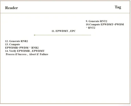
Step 9: Tag generate Random Number Tag Two(RNT2) using Random Number Tag One(RNT1).
Step 10: Tag compute Encrypted Password Most Tag (EPWDMT) using Random Number Tag Two(RNT2) and Password Most(PWDM).
Step 11: Tag send Encrypted Password Most Tag(EPWDMT) and Electronic Product Code(EPC) to Reader.
Num-3.3. PROPOSED AUTHENTICATION SCHEMECHAPTER 3. AUTHENTICATION SCHEME
ber Reader One(RNR1).
Step 13: Reader compute Encrypted Password Most Reader(EPWDMR) using Ran-dom Number Reader(RNR2) and Password Most(PWDM).
Step 14:Checking of Encrypted Password Most Reader(EPWDMR)=Encrypted Pass-word Most Tag(EPWDMT )is completed. whether it is true the process continues else communication is finished.
Figure 3.5: Proposed RFID Authentication Scheme
3.3.2
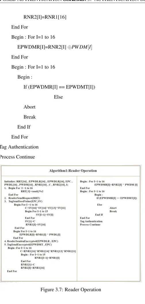
Reader Operation
Reader is read the information from the tags after store in database. Rearder operation is shown in Fig. 3.6.
Initialize: RRT[16] , EPWDLR[16] , EPWDLR[16] , EPC , PWDL[16] , PWDM[16] RNR1[16] , C , RNR2[16] , I; 1. Begin For I = 1 to 16 RRT[ I]=rand()÷2 End For 2. ReaderSendRequest(RRT) 3. TagSendSeedValue(EPC,SV) Begin For I =1 to 16 19
3.3. PROPOSED AUTHENTICATION SCHEMECHAPTER 3. AUTHENTICATION SCHEME
Figure 3.6: Proposed RFID Authentication Scheme
C=SV[16]⊕SV[14]⊕SV[13]⊕SV[11]
Begin For I=1 to 15 SV[I+1]=SV[I] End For
SV[1]=C
RNR1[I]=SV[16] End For
Begin For I=1 to 16
EPWDLR[I]=RNR1[I]⊕PW DL[I]
End For
4. ReaderSendenEncrypted(EPWDLR , EPC) 5. TagSendEncrypted(EPWDMT , EPC)
Begin :For I=1 to 16
C=RNR1[16]⊕RNR1[14]⊕RNR1[13]⊕RNR1[11]
Begin : For I=1 to 15 RNR1[I+1]=RNR1[I] End For
3.3. PROPOSED AUTHENTICATION SCHEMECHAPTER 3. AUTHENTICATION SCHEME
RNR2[I]=RNR1[16] End For
Begin : For I=1 to 16
EPWDMR[I]=RNR2[I]⊕PW DM[I]
End For
Begin : For I=1 to 16 Begin : If (EPWDMR[I] == EPWDMT[I]) Else Abort Break End If End For Tag Authentication Process Continue
Figure 3.7: Reader Operation
3.3. PROPOSED AUTHENTICATION SCHEMECHAPTER 3. AUTHENTICATION SCHEME
3.3.3
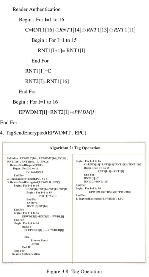
Tag Operation
Tag hold information about that things. That information is store in barcode. Tag hold a unique Electronic product code. Tag operation is shown in Fig.3.7.
Initialize: EPWDLT[16] , EPWDMT[16] ,SV[16] , RNT1[16] , RNT2[16] , I , EPC , C
1. ReaderSendRequest(RRT) Begin : For I=1 to 16
SV=rand()÷2 End For
2.TagSendSeedValue(EPC , SV )
3. ReaderSendEncrypted(EPWDLR , EPC) Begin : For I=1 to 16
C=SV[16]⊕SV[14]⊕SV[13]⊕SV[11]
Begin : For I=1 to 15 SV[I+1]=SV[I] End For
SV[1]=C
RNT1[I]=SV[16] End For
Begin : For I=1 to 16
EPWDLT[I]=RNT1[I]⊕PW DL[I]
End For
Begin :For I=1 to 16 Begin :
If( EPEDLT[I] = = EPWDLR[I]) Else
Process Abort Break End If End For
3.3. PROPOSED AUTHENTICATION SCHEMECHAPTER 3. AUTHENTICATION SCHEME
Reader Authentication Begin : For I=1 to 16
C=RNT1[16]⊕RNT1[14]⊕RNT1[13]⊕RNT1[11]
Begin : For I=1 to 15 RNT1[I+1]= RNT1[I] End For
RNT1[1]=C
RNT2[I]=RNT1[16] End For
Begin : For I=1 to 16
EPWDMT[I]=RNT2[I]⊕PW DM[I]
o cm End For
4. TagSendEncrypted(EPWDMT , EPC)
Figure 3.8: Tag Operation
3.3.4
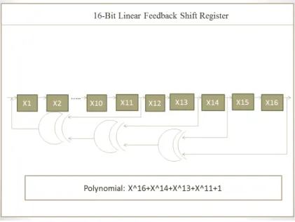
Linear Feedback Shift Register
Linear Feedback Shift Register(LFSR) is a shift register its input bit is a linear function of its previous state. The most commonly used linear function of single bits is
3.3. PROPOSED AUTHENTICATION SCHEMECHAPTER 3. AUTHENTICATION SCHEME
or. An Linear Feedback Shift Register(LFSR)is most often a shift register its input bit is driven by the exclusive or (EXOR) of the whole shift register value. The initial value of the Linear Feedback Shift Register(LFSR) is called Seed Value. So the register has a definite number of possible states. Though, an Linear Feedback Shift Register(LFSR)with a select feedback function can be produced a order of bits that appeared random number (20) (15).
16-bit Linear Feedback Shift Register(LFSR) as maximum length feedback polyno-mialX16+X14+X13+X11+1 creates 216−1=65535 random outputs (11) (13).
The diagram for 16-bit linear feedback shift register(LFSR) with maximum length polynomial is shown in Fig.3.8.
Figure 3.9: 16-bit Linear Feedback Shift Register with Maximum Length Feedback Poly-nomialX16+X14+X13+X11+1
Chapter 4
Simulation & Results
Simulation and Implementation
Chapter 4
Simulation & Results
This chapter gives overview about simulation and security analysis.Section 4.1 explain about simulation and implementation. Section 4.2 explain about security analysis.
4.1
Simulation and Implementation
Linear feedback shift register is used to described the proposed RFID authentication scheme. This approach is simulated in C language.
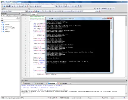
Fig 4.1 shows simulation output of the propose scheme. Where SV=001110111100101. RR=1011011011110111. PWDL=1001011010110011. PEDM=1100110011001100. RNT1=110100111011110. RNT2=1011110111100101. RNR1=1101001111011110. RNR2=1011110111100101. EPWDLT=0100010101101101. EPWDLR=0100010101101101. EPWDMT=0111000100101001. EPWDMR=0111000100101001.
Whenever the EPWDLR and EPWDMR mathces with the value of EPWDLT and EP-WDMT respectively mutual authentication becomes high.
R:Generate RR
4.1. SIMULATION AND IMPLEMENTATIONCHAPTER 4. SIMULATION & RESULTS
Figure 4.1: Simulation Results of Proposed Scheme
RR=1011011011110111
R send request to T: RR=101101110111 T:Generate SV
16 Times SV=rand()%2 SV=001110111100101
T send SV and EPC to R: SV=0011110111100101 EPC=ACE14789BD105612 R: Generate RNR1
16 Times C=SV[16] XOR SV[14] XOR SV[13] XOR SV[11] SV[I+1]=SV[I] SV[I]=C RNR1[I]=SV[16] RNR1=1101001111011110 PWDL=1001011010110011 R : Compute EPWDLR
16 Times EPWDLR[I]=RNR1[I] XOR PWDL[I]
EPWDLR=0100010101101101
Reader send EPC and EPWDLR to Tag: EPC=ACE14789BD105612 EPWDLR=0100010101101101 T : Generate RNT1
4.1. SIMULATION AND IMPLEMENTATIONCHAPTER 4. SIMULATION & RESULTS
RNR1[I]=SV[16] SV[I+1]=SV[I] SV[I]=C C=SV[16] XOR SV[14] XOR SV[13] XOR SV[11] SV 001111011110010 1 1 0 011110111100101 1 1 2 1 111101111001011 0 0 3 1 111011110010110 0 0 4 1 110111100101100 1 1 5 1 101111001011001 1 1 6 0 011110010110011 0 0 7 1 111100101100110 0 0 8 1 111001011001100 1 1 9 1 110010110011001 1 1 10 1 100101100110011 1 1 11 0 001011001100111 1 1 12 0 010110011001111 0 0 13 1 101100110011110 1 1 14 0 011001100111101 1 1 15 1 110011001111011 0 0 16 1 100110011110110 0 0
Table 4.1: RNR1 generate by Reader
RNR1[I] PWDL[I] EPWDLR[I] = RNR1[I] XOR PWDL[I]
1 0 1 1 2 1 1 0 3 1 0 1 4 1 0 1 5 1 1 0 6 0 1 1 7 1 0 1 8 1 1 0 9 1 0 1 10 1 1 0 11 0 1 1 12 0 0 0 13 1 1 0 14 0 0 0 15 1 0 1 16 1 1 0
Table 4.2: EPWDLR compute by Reader
16 times C=SV[16] XOR SV[14] XOR SV[13] XOR SV[11] SV [I+1] = SV[I]
4.1. SIMULATION AND IMPLEMENTATIONCHAPTER 4. SIMULATION & RESULTS
RNT1[I]=SV[16]
RNRT1[I]=SV[16] SV[I+1]=SV[I] SV[I]=C C=SV[16] XOR SV[14] XOR SV[13] XOR SV[11] SV 001111011110010 1 1 0 011110111100101 1 1 2 1 111101111001011 0 0 3 1 111011110010110 0 0 4 1 110111100101100 1 1 5 1 101111001011001 1 1 6 0 011110010110011 0 0 7 1 111100101100110 0 0 8 1 111001011001100 1 1 9 1 110010110011001 1 1 10 1 100101100110011 1 1 11 0 001011001100111 1 1 12 0 010110011001111 0 0 13 1 101100110011110 1 1 14 0 011001100111101 1 1 15 1 110011001111011 0 0 16 1 100110011110110 0 0
Table 4.3: RNT1 generate by Tag
RNT1=110100111011110 PWDL=1001011010110011 T : Compute EPWDLT
16 Times EPWDLT[I]=RNT1[I] XOR PWDL[I] T : Verify EPWDLT , EPWDLR
EPWDLT= 0100010101101101 EPWDLR=0100010101101101 Process If Success, Abort if failure
Reader Authentication T : Generate RNT2
RNT1=1101001111011110
16 times C=RNT1[16] XOR RNT1[14] XOR RNT1[13] XOR RNT1[11] RNT1 [I+1] = RNT1[I]
RNT1[I]=C
4.1. SIMULATION AND IMPLEMENTATIONCHAPTER 4. SIMULATION & RESULTS
RNT1[I] PWDL[I] EPWDLT[I] = RNT1[I] XOR PWDL[I]
1 0 1 1 2 1 1 0 3 1 0 1 4 1 0 1 5 1 1 0 6 0 1 1 7 1 0 1 8 1 1 0 9 1 0 1 10 1 1 0 11 0 1 1 12 0 0 0 13 1 1 0 14 0 0 0 15 1 0 1 16 1 1 0
Table 4.4: EPWDLR compute by Tag
EPWDLT[I] EPWDLR[I] EPWDLT[I] = EPWDLR[I]
1 1 1 T 2 0 0 T 3 1 1 T 4 1 1 T 5 0 0 T 6 1 1 T 7 1 1 T 8 0 0 T 9 1 1 T 10 0 0 T 11 1 1 T 12 0 0 T 13 0 0 T 14 0 0 T 15 1 1 T 16 0 0 T
Table 4.5: Reader Authentication
RNT2[I]=RNT1[16] RNT2=1011110111100101 PWDM=1100110011001100 T : Compute EPWDMT
4.1. SIMULATION AND IMPLEMENTATIONCHAPTER 4. SIMULATION & RESULTS
RNT2[I]=RNT1[16] RNT1[I+1]=RNT1[I] RNT1[I]=C C=RNT1[16] XOR
RNT1[14] XOR RNT1[13] XOR RNT1[11] RNT1 110100111101111 0 1 1 101001111011110 0 0 2 0 010011110111100 1 1 3 1 100111101111001 1 1 4 0 001111011110011 1 1 5 0 011110111100111 1 1 6 1 111101111001111 0 0 7 1 111011110011110 0 0 8 1 110111100111100 1 1 9 1 101111001111001 1 1 10 0 011110011110011 1 0 11 1 111100111100110 1 1 12 1 111001111001101 0 1 13 1 110011110011011 1 0 14 1 100111100110110 1 1 15 0 001111001101101 0 1 16 1 011110011011011 0 0
Table 4.6: RNT2 generate by Tag
RNT2[I] PWDM[I] EPWDMT[I] = RNT2[I] XOR PWDM[I]
1 1 0 1 2 0 0 0 3 1 1 0 4 0 1 1 5 0 0 0 6 1 0 1 7 1 1 0 8 1 1 0 9 1 0 1 10 0 0 0 11 1 1 0 12 1 1 0 13 1 0 1 14 1 0 1 15 0 1 1 16 1 1 1
Table 4.7: EPWDMT compute by Tag
EPWDMT=0111000100101001
Tag send EPWDMT and EPC to Reader: EPWDMT = 0111000100101001. EPC
4.1. SIMULATION AND IMPLEMENTATIONCHAPTER 4. SIMULATION & RESULTS
= ACE14789BD105612 R : Generate RNR2
RNR1=1101001111011110
16 times C=RNR1[16] XOR RNR1[14] XOR RNR1[13] XOR RNR1[11] RNR1 [I+1] = RNR1[I]
RNR1[I]=C
RNR2[I]=RNR1[16]
RNR2[I]=RNR1[16] RNR1[I+1]=RNR1[I] RNR1[I]=C C=RNR1[16] XOR
RNR1[14] XOR RNR1[13] XOR RNR1[11] RNR1 110100111101111 0 1 1 101001111011110 0 0 2 0 010011110111100 1 1 3 1 100111101111001 1 1 4 0 001111011110011 1 1 5 0 011110111100111 1 1 6 1 111101111001111 0 0 7 1 111011110011110 0 0 8 1 110111100111100 1 1 9 1 101111001111001 1 1 10 0 011110011110011 1 0 11 1 111100111100110 1 1 12 1 111001111001101 0 1 13 1 110011110011011 1 0 14 1 100111100110110 1 1 15 0 001111001101101 0 1 16 1 011110011011011 0 0
Table 4.8: RNR2 generate by Reader
R:Compute EPWDMR
RNR2=1011110111100101 PWDM=1100110011001100
16 times EPWDMR[I]=RNR2[I] XOR PWDM[I] EPWDMR=0111000100101001
R : Verify EPWDMR , EPWDMT
EPWDMR = 0111000100101001 EPWDMT=0111000100101001
4.1. SIMULATION AND IMPLEMENTATIONCHAPTER 4. SIMULATION & RESULTS
RNR2[I] PWDM[I] EPWDLT[I] = RNR2[I] XOR PWDM[I]
1 1 0 1 2 0 0 0 3 1 1 0 4 0 1 1 5 0 0 0 6 1 0 1 7 1 1 0 8 1 1 0 9 1 0 1 10 0 0 0 11 1 1 0 12 1 1 0 13 1 0 1 14 1 0 1 15 0 1 1 16 1 1 1
Table 4.9: EPWDLR compute by Tag
EPWDMT[I] EPWDMR[I] EPWDMT[I] = EPWDMR[I]
1 1 1 T 2 0 0 T 3 0 0 T 4 1 1 T 5 0 0 T 6 1 1 T 7 0 0 T 8 0 0 T 9 1 1 T 10 0 0 T 11 0 0 T 12 0 0 T 13 1 1 T 14 1 1 T 15 1 1 T 16 0 0 T
Table 4.10: Tag Authentication
Process If Success, Abort if failure Tag Authentication
4.2. SECURITY ANALYSIS CHAPTER 4. SIMULATION & RESULTS
Parameters EPC Global Au-thentication Proposed Scheme based on 8-Bit LFSR Proposed Scheme based on 16-Bit LFSR Proposed Scheme based on Diffie Hellman Algo-rithm
Man in middle at-tack
low moderate High High
Mutual Authenti-cation
low moderate High High
Cost less expensive less expensive Medium expen-sive
More expensive Operation used XOR
Opera-tion, Random() function XOR Operation 8-bits LFSR, Seed value, rand() function, EXOR Opera-tion, Random() function EXOR Operation 16-bits LFSR, Seed value, rand() function Mod operation, Power Operation, Public value P and Q
Table 4.11: Comparison between Existing Scheme and Proposed Scheme
4.2
Security Analysis
Man-in-the-middle attack prevention: In this approach a man-in-the-middle attack is pre-vented. So, this is depend on a mutual authentication. Proposed scheme share only Seed value(SV), not random number (18).
Mutual authentication :Authentication for Reader and tag is checking through
EP-WDLR=EPWDLT and Authentication for Tag to reader is checking from EPWDMR=EPWDMT. Authentication is fail. And it finishes the connection else connection has been established between tag and reader. So, mutual authentication is hold in this given scheme (3) (9).
Chapter 5
Conclusion and Future Work
Conclusion
Chapter 5
Conclusion and Future Work
In this thesis, an efficient Radio Frequency Identification mutual authentication scheme is proposed using 16-bits Linear feedback shift register.16-bit random number is find using 16-bit linear feedback shift register. This proposed scheme is improving drawback of EPC global class-1 generation-2 standard(C1G2) communication authentication scheme. Using this scheme mutual authentication and man-in-middle attack are prevention.
The debate around technology and privacy has been going on to many years. Such that technologies have become increasingly sophisticated for intercepting messages, the ability of other people to see what we are doing has endangered an individual’s privacy in our society. Inevitably, users place high priority on privacy and security in every RFID application.
Bibliography
[1] D.M. Konidala and Z.Kim and K.Kim. ”A Simple and Cost Effective RFID Tag–Reader Mutual Authenticati on Scheme”, In: Proceedings International Con-ference on RFID Security, vol.4, 2007, pp.141-152.
[2] P.Peris-Lopez and T.-L.Lim and T.Li, ”Providing Stronger Authentication at a Low Cost to RFID Tags Operating under the EPCglobal Framework”, Proceedings of IEEE/IFIP International Conference on Evolutionary Computation, vol.2, Dec.17-20, 2008, pp.159-166.
[3] M. R. Rieback, B. Crispo, and A. S. ”Tanenbaum, RFID Guardian: A Battery-Powered Mobile Device for RFID Privacy Management”, IEEE Transactions on Industrial Electronics, 2005, pp.184-194.
[4] A. Juels, D. Molner and D. Wagner, ”Security and Privacy Issues in EPassports”, Proceedings of the First International Conference on Security and Privacy for Emerging Areas in Communications Networks, vol.24, 2005, pp.74-88.
[5] S. A. Weis, S. E. Sarma, R. L. Rivest, and D. W. Engels. ”Security and Privacy aspects of Low-cost Radio Frequency Identifcation Systems”, 2004, pp.201-212. [6] L. Bolotnyy, and G. Robins, ”Multi-Tag RFID Systems Security in RFID and Sensor
Networks”, Auerbach Publications, CRC, Press, Taylor and Francis Group, 2009, pp.3-28.
[7] L. Bolotnyy, and G. Robins. ”The Case for Multi-Tag RFID Systems”, IEEE In-ternational Conference on Wireless Algorithms, Systems and Applications, 2007, pp.174-186.
BIBLIOGRAPHY BIBLIOGRAPHY
[8] H. Chae, and K. Han. ”Combination of RFID and Vision for Mobile Robot Local-ization”, IEEE International Conference Intelligent Sensors, Sensor Networks and Information Processing, 2005, pp.75-80.
[9] Yu-Jung Huang and Wei-Cheng Lin and Hung-Lin Li. ”Efficient Implementation of RFID Mutual Authentication Protocol”, IEEE Transactions on Industrial Electron-ics, 2011.
[10] Kaoutr Elkhiyaoui, Erik-Oliver Blass, and Refik Molva. CHECKER:”On-site Checking in RFID-based Supply Chains”, Proceeding of the fifth ACM Conference on Security and Privacy in Wireless and Mobile Netwoks, 2012, pp.173-184. [11] Yu-Jung Huang , Ching-ChienYuan , Ming-KunChen , Wei-ChengLin and
Hsien-Chiao Teng, ”Hardware Implementation of RFID Mutual Authentication Protocol”, IEEE Transactions on Industrial Electronic, 2010, pp.1573-1582.
[12] Hou-Jen Ko and Shen-Fu Hsiao. ”Design and Application of Faith Fully Rounded and Truncated Multipliers with Combined Deletion”, Reduction, Truncation, and Rounding, IEEE/ACM Transaction on Networking, vol.8, 2011, pp.304-308. [13] M.J. Schulte, J.G.Hansen and J.E.Stine, ”Reduced Power Dissipation Through
Trun-cated Multiplication”, Proceedings IEEE International Workshop Low Power De-sign, 1999, pp.61-69.
[14] J. Bringer, H. Chabanne and E. Dottax, ”A Lightweight Authentication Protocol Se-cure against Some Attacks”, International workshop on Security, Privacy and Trust in Pervasive and Ubiquitous Computing, 2006, pp.28-33.
[15] H.Y. Chien and SASI. ”A New Ultralightweight RFID Authentication Protocol Pro-viding Strong Authentication and Strong Integrity”, IEEE Transactions on Depend-able and Secure Computing,vol.4, 2007, pp.337-340.
[16] H.Y. Chien and C.W. Huang. ”Security of Ultra-Lightweight RFID Authentication Protocols and Its Improvements”, ACM Operating System Review, vol.41, 2007, pp.83-86.
BIBLIOGRAPHY BIBLIOGRAPHY
[17] M. David and N.R. Prasad. ”Providing Strong Security and High Privacy in Low-Cost RFID Networks”, Procedings of Security and Privacy in Mobile Information and Communication Systems, 2009, pp.172-179.
[18] T. Li and G. Wang. ”Security Analysis of Two Ultra-Lightweight RFID Authen-tication Protocols”, Proceedings of International Information Security Conference, 2007, pp.59-66.
[19] R. Want. ”RFID – A Key to Automating Everything”, 2004, pp.56-65.
[20] A. Juels. ”RFID Security and Privacy: A Research Survey”, The IEEE Journal on the Selected Areas in Communications, 2006, pp.381-384. .
BIBLIOGRAPHY BIBLIOGRAPHY
Dissemination of Work
1. Hakim Singh and Ashok Kumar Turuk. ”A Tag- Reader Authentication Scheme for RFID Systems”, Proceedings of IFERP International Conference on Emerging Trends in Engineering and Technology, 10th May 2015, pp.18-23.