2017 П Р И К Л А Д Н А Я М Е Х А Н И К А Том 53, № 3
H . M . S i l v a , C . D . C a r v a l h o , N . R . P e i x i n h o
ELASTO-PLASTIC BEHAVIOR OF ALUMINUM FOAMS SUBJECTED TO COMPRESSION LOADING
Department of Mechanical Engineering, University of Minho,
Campus of Azurém,4800-058 Guimarães, Portugal; email:[email protected]
Abstract. The non-linear behavior of uniform-size cellular foams made of aluminum is investigated when subjected to compressive loads while comparing numerical results obtained in the Finite Element Method software (FEM) ANSYS workbench and ANSYS Mechanical APDL (ANSYS Parametric Design Language). The numerical model is built on AUTODESK INVENTOR, being imported into ANSYS and solved by the Newton – Raph-son iterative method. The most similar conditions were used in ANSYS mechanical and ANSYS workbench, as possible. The obtained numerical results and the differences be-tween the two programs are presented and discussed.
Key words: plasticity, finite element method, cellular material, non-linear analysis, alu-minium foam.
1. Introduction.
Engineers make efforts to reduce the pores from casted parts, welded joints, or coatings, because there is a common idea that pores always act as a defect. With this common think-ing, it is hard to accept that metallic structures that include pores can be quite effective for structural applications. Cellular structures are structures that have pores. Some struc-tures don’t have a regular pattern (Eg. Foams), but some do have a regular pattern (Eg. Honeycombs, Hollow Sphere agglomerates). Cellular materials have advantages, such as the high specific strength, and the associated reduction of cost that is inherent to its use. In fact, and as it is logical, a cellular material has a fraction of its weight in comparison with the bulk base cell. One can then achieve a reduction of material cost. The mechanical properties and the mechanical behavior of cellular materials depend significantly on the porosity [4]. The influence of geometric variables related to the pores on the mechanical behavior is not fully understood at present. Some types of regular cellular solids, such as spherical inclusions, have already been studied by [8].The authors studied the influence of parameters related to the pores on the global behavior of those solids. The authors proved that the studied variables are relevant for the mechanical behavior and determined the most relevant variables to be used on optimization processes [8]. Gibson and Ashby have found that, on cellular solids, the main factor governing the mechanical behavior in comparison to the bulk solid is the relative density [5]. Nieh et al. investigated the mechanical properties of open-cell 6101 aluminum foams with different densities (5 – 10%) and morphologies (4 – 16 cells cm-1) subjected to compression loadings. The authors concluded that the relative density is the main variable controlling the modulus and yield strength of foams. The cell size appears to have no significant effect on the strength of foams at a fixed density. However, it is found that the cell shape has effect on the strength of foams [6]. Rakow and Wass [7] investigated size effects on the shear response of alu-minium foams having manufactured foam samples and subjected them to static and quasi-static low-rate shear deformation using a loading fixture designed for the produced materials. The authors have found that for the range of densities examined, the shear
modulus shows a linear dependence on relative density, while the ultimate strength follows a non-linear power law. [7] The effect of strut geometry on the yielding behavior of open-cell foams has been studied by Xie and Chan. The authors performed a micromechanical analysis with the aim to investigate the effect of strut geometry on the Yielding behavior of open-cell foams. The authors tested different cross-sections: rectangular, circular, and equi-lateral triangular shapes. The authors found that the shape of the plastic-yield surface is de-pendent on the relative density and the cross-sectional shape of the structure. The authors also concluded, by means of numerical results, that open-cell foams with asymmetrical sec-tional struts have different tensile and compressive collapse strength [9]. Andrews et. Al [1] tested the compressive and tensile behavior of Al foams having compared the uniaxial compressive modulus, tensile modulus and strength of several aluminum foams with models for cellular solids. The authors have found that the foam experimental results regarding open cell have good correlation with the model. The closed cell foams have modulus and strengths that are quite lower than the models predicted values. The authors concluded that the discrepancy is due to micro defects which cause bending instead of stretching of the cell walls [1].The effects of cell size on compressive properties of aluminum foams were stud-ied by Cao et al [2]. The authors studstud-ied the effects of cell size on the quasi-static and dy-namic compressive properties of open cell aluminum foams. The authors found that the elastic moduli and compressive strengths of the studied aluminum foam are not only dependent on the relative density but also dependent on the cell size of the foam under both quasi-static loading and dynamic loading [2].
2. Numerical procedure.
A cellular solid, shown in the fig. 1 was tested in compression. A metallic foam of uni-form cell size is characterized by two parameters: the distance between two adjacent hole centers, with the value of 1,38 mm, and by the radius of the larger holes, with the value of 7,5 mm [3]. The cellular solid has a regular pattern and has a wall around it having a thick-ness of 0,4 mm. The outer diameter of the model is 16,36 mm. The CAD model for the studied geometry with wall and the real geometry are presented in the fig. 1.
Fig. 1. Studied geometry: real (left) and CAD model (right) [3].
In this work, the model was solved used the Newton – Raphson iterative method. On the «Newton – Raphson» method, the load is subdivided into a series of load incre-ments. The load increments can be applied over several load steps. Each load step can have several substeps. The load is incremented on each substep. The aim is to obtain conver-gence. Convergence may be obtained, when the solution sat-isfies the convergence norm, which has several parameters, being the tolerance an important parameter for conver-gence. The lower the tolerance, the more accurate the so-lution is, but usually more iterations are needed in order to achieve a converged solution. The chosen element in AN-SYS APDL is Solid Tetragonal with 4 nodes, known as Fig. 2. Geometry of the
cel-lular solid, taken from Auto-desk Inventor [3].
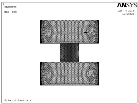
SOLID285. Both cylinders and cellular solid are meshed with the same parameters. In AN-SYS workbench, the solid elements used are SOLID186 for the foam and walls and SOLID187 for the cylinders. Other elements were used in ANSYS Workbench, such as the contact element CONTA174. In order to model contact, the element TARGE170 was used to assign the contact surfaces. The element SURF154 was also applied to allow related sur-face effects. It is applied a distributed compressive load on the top area of the top cylinder, and DOF constraints on the bottom area of the bottom cylinder. All 3 translation DOF and 3 rotation DOF were constrained. The applied pressure is:1,17 MPa. The FEM model is com-posed by a cellular solid and by two cylinders. The cylinders have 50 mm diameter and 10 mm height, and are located at the bottom and top of the model. Fig. 3 shows the mesh of the FEM model. The cellular solid is represented in red, while the cylinders are shown in green. The mesh is a tetragonal free mesh, and has an average element length of 0,0012 m.
Fig. 3. Cellular solid between two cylinders
The used material for the foam is pure Aluminum. Steel was only used for the cylin-ders, in order to ensure the less influence possible of the cylindrical plates on the behav-ior of the cellular solid. The Young’s modulus of the aluminum was determined by tensile test. Table 1 presents the aluminum and steel properties used on the ANSYS analysis. The material is assumed to be isotropic:
Table 1. Elastic properties of steel and Aluminum used in the FEM simulation.
Table 1
Aluminum Steel
Young Modulus 57 10 9 [Pa] 210 10 9 [Pa]
Poisson coefficient 0,33 0,29
Density 2700 [kg / m ] 3 7800 [kg / m ] 3
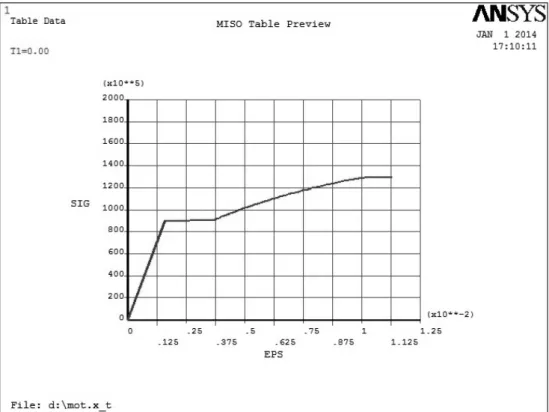
A multilinear isotropic hardening model was used, using Mises model, in order to simulate plasticity behavior of the cellular solid. The plasticity model was used only for aluminum. Figure 4 presents the stress-strain curve used in the software, which includes plasticity behaviour.
Fig. 4. Stress-Strain curve used for nonlinear material modeling.
Solution converges on every substep. The convergence criterion force based with con-vergence settings as presented in table 2:
Table 2. Force convergence criterion settings
Table 2 Parameter Value
Reference value Calculated
Tolerance 1*10-3
Norm L2
Minimum reference value 1*10-5
The solution parameters are shown in the table 3: Table 3. Nonlinear solution parameters
Table 3 Analysis type Large displacement Static
Solution Method Newton-Raphson
Number of load steps 1
Number of substeps 50
Automatic step time OFF
3. Results.
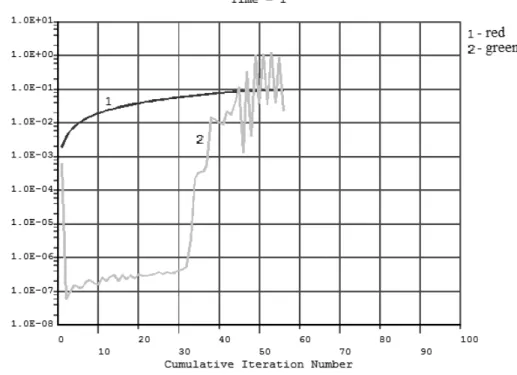
Figure 5 shows the absolute convergence norm of the force (red), and the crite-rion (green) on all iterations, as presented by ANSYS APDL.
Fig. 5. Absolute convergence norm value on each iteration on ANSYS mechanical APDL.
Based on the fig. 5, one can say that the convergence criterion increased during the analysis and that convergence was observed on every substep. The program was able to ob-
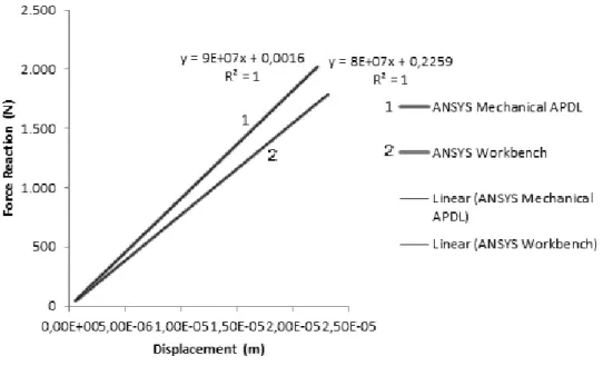
Fig. 6. Force reaction-Displacement curve for ANSYS workbench and ANSYS me-chanical
tain a solution quite easily, given the simulation conditions. On 50 substeps, only 56 iterations were performed.The mechanical behavior of these geometries has been already studied [3], being presented in fig. 6 the Force-Displacement curve obtained for the same geometry and conditions with ANSYS workbench [3]. A simulation, using similar condi-tions was done on ANSYS Mechanical APDL in the present work. The maximum Z dis-placement result UZ was taken from the top area, where the load is applied, and the sum of all FZ reaction forces were taken from the bottom area, where the model is constrained. The maximum absolute value of the displacement UZ is plotted with the total force reaction in the Z direction, which is the sum of the force reaction values for all nodes. The chart of the fig. 6 shows the displacement-force reaction for every one of the 50 substeps.
The chart contains 50 points, being each point the result of the last iteration of each substep, when the solution converges. One can see that there are differences between the curves, mainly the slope of the elastic domain, which is higher for ANSYS mechanical and the strain energy which is clearly higher on ANSYS workbench.
The stiffness K can be defined from the linear relation between load ( )P and dis-placement ( ) within the elastic region: KP . Another measure of the stiffness is the stiffness per mass unit (Km), which is given by: Km K m, where is he mass. In graphical
terms, the stiffness can be determined by the slope of the elastic part of the Force-Displacement chart, which is a straight line. The Fig. 7 shows the graphical determination of stiffness for the obtained results. The corresponding values of stiffness and mass are pre-sented in the table 4.
Fig. 7. Determination of the stiffness.
Table 4. Values of the stiffness and of the stiffness per mass unit.
Table 4 Stiffness (N/m) Mass (kg) Specific Stiffness(N/m*kg)
Workbench 8*107 1,64*10-3 4,88*1010
4. Discussion of results.
From the analysis of load-displacement curves one can observe that there is a non-linear relation between force reaction and displacement after reaching yield point, therefore the applied load was high enough for the cellular solid to go beyond yield. One can then conclude that the simulation conditions, namely, mesh parameters, load intensity, and element type were reasonable and adequate for the studied problem. The converged force value strictly increases in absolute value with the displacement, as shown in the fig. 5 which concurs that the higher the displacement, the higher the load needed for the solution to converge. The Force-displacement curve has a typical behavior, having a linear part, for the lower displacements, and a non-linear part for the post-yielding (plastic) zone. The slope of the elastic part of the curve is higher in ANSYS workbench than in ANSYS mechanical. This can be explained by the fact that in ANSYS workbench it is possible to disable non-linear effects on the cylinders and other options that make the displacement on the cyl-inders equal to 0. This is not possible in ANSYS mechanical. It was made an effort to emu-late as much as possible the simulation conditions on both ANSYS programs. Although the curves presented in figure 7 show differences in terms of slope: 8*1010 to 9*1010, which are the values of the stiffness, the values of stiffness per mass unit are quite similar. The differences obtained in the stiffness values can be due to differences in internal recogni-tion of the mass in ANSYS workbench and ANSYS mechanical APDL. In fact, and as the geometry was imported from Inventor to ANSYS mechanical, some details are hard to re-produce, such as the minimum mesh size, and the elements used in ANSYS workbench did not work well on ANSYS mechanical. It is found however, that the mesh used in ANSYS APDL was fine enough to obtain converged results. The difference between the definition of contacts, i.e., the contacts between the steel cylinders and the foam were defined on ANSYS workbench, while they were not defined in ANSYS mechanical APDL. On AN-SYS workbench, the contact element CONTA174 was used. TARGE170 was also used to assign the contact surfaces to the associated contact element. The surface element SURF154 was used to allow associated surfact effects. The elements used: SOLID 186 and SOLID 187 in ANSYS workbench lead to difficulties in meshing in ANSYS APDL. As such, SOLID285 elements were used. Also quadrilateral mesh was used in ANSYS work-bench for the steel cylinders, and due to that impossibility in ANSYS mechanical, tetrago-nal mesh was used. The difference between the elements and mesh is the main explanation for the observed differences in numerical results.
5. Conclusions.
It is possible to conclude that it was easy to achieve convergence for this particular problem. This may suggest that the simulation conditions were adequate. The load was high enough to pass yield point and enter the plastic domain. Some differences in software op-tions are present between the two programs used which limits the aim of reproducing exact simulation conditions, despite the best efforts. The most significant differences were associ-ated to element type and mesh details. Also the internal recognition of geometry from CAD import might explain some result variation. Despite that fact, a reasonable agreement was established for the modeling conditions, and consequently, also for the stiffness values.
Р Е З Ю М Е. Досліджено нелінійну поведінку одноріднихкліткоподібних пін, зроблених з алюмініюіпідданихстиску. Прицьомупорівнюютьсячисловірезультати, отриманідвомапрограм -нимипакетами: Finite Element Method software (FEM) ANSYS workbench і ANSYS Mechanical APDL (ANSYS Parametric Design Language). Числовамодельпобудованав AUTODESK INVENTOR ідалі імпортуєтьсяв ANSYS ірозв‘язуєтьсяметодомНьютона – Рафсона. Використано якомогаближчі умовиувказанихпакетах. Представленоіпрокоментованоотриманічисловірезультатиіспостере -женівідмінностіміждвомапакетами.
1. Andrews E., Sanders W., Gibson L.J. Compressive and tensile behaviour of aluminum foams // Materials Science and Engineering. – 1999. – A270. – P. 113 – 124.
2. Cao X.Q., Wang Z.H., Ma H.W., Zhao L.M., Yang G.T. Effects of cell size on compressive properties of aluminum foam // Trans. Nonferrous Met. SOC. China. – 2006. – 16. – P . 351 – 356.
3. Carvalho C.D. Simulação numérica e verificação experimental do comportamento elástoplástico de espumas metálicas, MSc. Thesis,University of Minho (2012) [In Portuguese].
4. Degischer H.P, Kriszt B. Handbook of Cellular Metals: Production, Processing, Applications, Wiley-VCH Verlag GmbH & Co. KGaA (2002).
5. Gibson L.J., Ashby M.F. Cellular S olids. Structure and P roperties. 2nd edition. – Cam.:Cambridge
Uni-versity Press, 1997. – 532p.
6. Nieh T.G, Higashi K., Wadsworth J. Effect of cell morphology on the compressive properties of open-cell aluminum foams // Materials Science and Engineering. – 2000. – A283. – P. 105 – 110.
7. Rakow J.F., Waas A.M. Size effects and the shear response of aluminum foam // Mechanics of Materi-als. – 2005. – 37. – P. 69 – 82.
8. Silva H.M., Peixinho N.R., Silva F.S. Numerical study on the sensitivity analysis for strength and stiff-ness of regular cellular solids // Int. J. of Applied Research in Mechanical Engineering. – 2013. – 3, № 1. – P. 93 – 98.
9. Xie L.S., Chan K.C. The effect of strut geometry on the yielding behavior of open- cell foams // Int. J. of Mech. Sci. – 2006. – 48. – P. 249 – 255.
From the Editorial Board: The article corresponds completely to submitted manuscript.
![Fig. 1. Studied geometry: real (left) and CAD model (right) [3].](https://thumb-us.123doks.com/thumbv2/123dok_us/11032586.2990521/2.892.192.702.634.831/fig-studied-geometry-real-left-cad-model-right.webp)