A Framework for Agile Development of
Simulation-Based System Design Tools
Ralph Maschotta, Sven J¨ager, Tino Jungebloud, and Armin Zimmermann
System and Software Engineering GroupFaculty of Computer Science and Automation Ilmenau University of Technology
Ilmenau, Germany
Email: see http://www.tu-ilmenau.de/sse/
Abstract—Analysis and validation using simulation is a helpful tool in systems engineering, but requires in-depth knowledge of various aspects of the system itself, the used model class(es), an appropriate software tool, and sometimes software engineering. Usually, this expertise is spread over a number of team members, and thus the development of a simulation-based system design tool is not a simple task.
This paper presents a framework enabling the rapid develop-ment of extensible and reusable simulation-based applications. It supports an agile, iterative, evolutionary, and architecture-centric software development process. The design of the framework together with its components as well as the corresponding software development process is described. As an example, an environment for the configuration and analysis of wireless sensor network applications in the aeronautic domain is presented, which has been designed and implemented based on the proposed environment.
Index Terms—Agile Development, System Design, Model Based Systems Engineering, Validation, MLDesigner, Wireless Sensor Network Simulation
I. INTRODUCTION
Model-based systems engineering has shown its benefits in academic and industrial projects, and is thus widely accepted for the design of complex systems. Among the reasons are an increased overall system quality through early validation of design decisions and a reduction of costly failure corrections in late development stages caused by defective system speci-fication documents. Thus, model-based system engineering is more and more accepted for industrial design, validation, and implementation of complex systems.
However, the amount of system-specific knowledge in a design project involved is increasing. Therefore, general-purpose modeling tools become more complex. But domain experts usually do not need all aspects and functional diversity of an underlying general-purpose modeling and simulation environment for their actual work. In case of repetitive tasks only a few amount of model-parameters will be changed. Thus, a simulation-based system design and validation software tool is needed for the actual system designers. This partitioning of responsibilities also enables system designers to concentrate on their task without the risk of introducing errors in the underlying system model of given constraints.
Contrary to traditional software development processes, the software development of simulation-based applications
requires an additional modeling phase for the underlying system model. This phase typically starts after the requirement specification phase but before software design and implemen-tation are carried out.
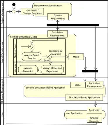
The modeling phase itself is usually tackled in an iterative manner. Analysis of input data, model design and refinement, experiment design and model simulation are repeated until the system model is sufficient for the desired purpose [1], [2]. After modeling specialists and domain experts have agreed on the system model and goals of evaluation, the common software development process continues. Figure 1 outlines this process in terms of a traditional software development process for a simulation-based application.
Proj ectEManage ment RequirementESpecification System Requirements Model EDevelopm ent Software EDevelopm ent User useEApplication Change Requests developESimulationEModel SystemEExp ert Simulation Requirements analyzeEDataE/ Results Model Model er execute Simulation designEModelEand Experiment developESimulation-BasedEApplication Model Appication Requirements Simulation-BasedEApplicatiion Application UseECasesE/ ChangeERequests [completeE[ accurate] [else]
Fig. 1. Simplified waterfall-like software development process for simulation-based applications (UML2 activity diagram).
Sequential software development processes as depicted in Figure 1 have well-known disadvantages [3]–[5]. For example: software development has to wait till the modeling phase will be completed. Additionally, in the modeling phase both, system and system modeling experts, should cooperate very closely. Otherwise, the risk of misunderstandings and loss of information is increasing. To prevent this, the system experts need additionally in-depth knowledge of system modeling as well as the particular modeling environment. In some cases, system experts have the role of a tool user, such that a wrapper application is indispensable.
Fortunately, the group of simulation-based system design applications has plenty of similarities. These parts could be encapsulated in reusable components and combined in a modular software architecture. As a result, a framework for rapid development of problem-aligned simulation-based system design applications is proposed in this paper.
The following two sections present design and implementa-tion of the framework for simulaimplementa-tion-based applicaimplementa-tions. Major framework components are outlined and briefly explained. An example is presented in Section IV, where the framework is used to build an environment for the configuration and analysis of wireless sensor network applications in the aeronautic do-main. This example application is based on the multi-domain simulation environment MLDesigner [6]–[8]. Finally, a more agile software development process based on the presented framework is described in Section V, showing the frameworks’ benefit.
II. DESIGN OF AFRAMEWORK FOR
SIMULATION-BASEDSOFTWARETOOLS
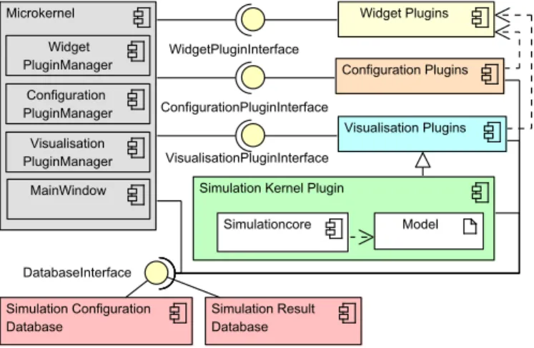
From an abstract point of view, the design could be de-scribed as a white box, component-based framework. It is based on the microkernel architectural pattern [9]. Each indi-vidual functional component is encapsulated into one separate plugin. Plugins are classified into the following types:
• Configuration Plugins: Components with the purpose of defining or modifying simulation input data and model configurations for dynamic model elements.
• Visualization Plugins: Components for static or interac-tive visualization and analysis of simulation results.
• Widget Plugins: Commonly used elements for the graph-ical user interface.
Each type of plugin is handled by a specialized plugin man-ager which loads the corresponding plugins during application startup. These plugin managers handle the encapsulated plugin elements.
The architecture is depicted in Figure 2 as a UML2 compo-nent diagram [10], consisting of microkernel, plugins, simula-tion kernel plugin, and database. Different colors visualize the various kinds of framework components. Data management is realized by two distinct databases handled within the microker-nel: The first one is used to provide simulation input parameter and data (Simulation Configuration Database), while the latter stores simulation results (Simulation Result Database). Both
databases are shared between simulation model logic and application plugins.
Configuration Plugins
Visualisation Plugins
Simulation Configuration Database
Simulation Kernel Plugin
Simulation Result Database Simulationcore Model Widget Plugins Microkernel Widget PluginManager Configuration PluginManager MainWindow Visualisation PluginManager ConfigurationPluginInterface VisualisationPluginInterface DatabaseInterface WidgetPluginInterface
Fig. 2. Main components of the framework.
Configuration and visualization plugins provide follow the Model View Controller pattern to create configuration and visualization widgets [9]. Each configuration plugin holds a reference to the configuration database from the microkernel. Visualization plugins have references to all databases to cope with multiple configuration sets and constrained result data.
WidgetPlugins can be created to implement reusable user
interface widgets. If components demand special widget types such as line-graph or box-plot, the microkernel’s plugin man-ager (WidgetPluginManager) can be utilized to create new instances of the defined widgets.
The simulation control, which includes a reference to a simulatable model and the simulation kernel, is realized as a plugin too. It organizes the instantiation, bootstrapping, and communication between application and the simulation kernel. The simulation kernel keeps references to the configuration and result database, which are used to configure the simulation and to store results.
The root widget is the sole component issued by the micro-kernel to minimize static and fixed application characteristics. It includes a hierarchical tree view to visualize all existing experiments and the loaded plugins.
Each experiment includes one set of simulation and con-figuration parameters as well as the appropriate results of the simulation. This data can be changed by the loaded configuration and visualization plugins. The corresponding plugin parameters are additionally included in the experiment. If the simulation of an experiment is started for the first time, the configuration of this experiment will be made constant.
III. IMPLEMENTATION
This section covers some implementation details of the framework, starting with its components and plugins, and followed by some technical details.
A. Framework Components and Plugins
The steps to create new framework components are de-scribed in the following.
1) New Plugin: To create a new plugin, a plugin class has to be created, which implements the PluginInterface. This interface definition includes load, unload, init, cleanup and some other management operations, e.g., to provide name, version and plugin category.
2) Configuration and Visualization Plugins: Configuration
plugins additionally need to implement the EditorInterface. This includes an abstract operation, which delivers a reference to the configuration database. In the same fashion, visualiza-tion plugins have to realize aVisualizationInterface. It includes abstract operations returning references to the configuration and simulation result database.
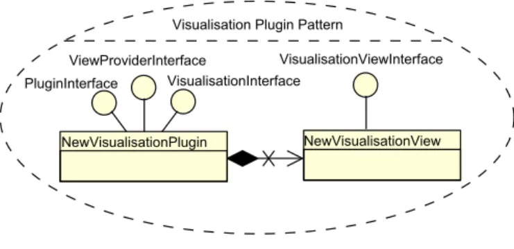
Moreover, the plugin class has to realise the
ViewProvider-Interface, which includes an abstract operation to create the
widget of the plugin. These widgets are provided by a view class implementing the EditorViewInterface or
Visualization-Viewinterface, respectively. This design allows to create
plug-ins based on the Model View Controller pattern [9].
Figure 3 shows the patterns to create a visualization plugin as a UML2 Composite Structure Diagram.
Visualisation Plugin Pattern
NewVisualisationPlugin NewVisualisationView PluginInterface
ViewProviderInterface
VisualisationInterface
VisualisationViewInterface
Fig. 3. Pattern to create a new visualization plugin.
3) Widget-Plugin: The widget plugin class has to realise
both the WidgetProviderInterface and the PluginInterface.
The WidgetProviderInterface includes a operation to create
a new widget instance. This operation will be used by the
WidgetPluginManager, if a client requests this type of widget.
The plugin is identified by its name.
4) Simulation Kernel: The simulation kernel plugin is a
kind of visualization plugin, and thus controlled by the plugin manager (see Section II). The simulation kernel uses both databases to access configuration data and to store simulation results. All elements in the simulation model dealing with input data or result generation may need to be modified. Data sources and sinks compatible with this framework are used and replace default model library entities.
B. Framework Details
1) Development Environment: Supporting multiple
operat-ing systems is important for wide framework applicability. All components are implemented in C/C++ using the Qt framework where possible to achieve the desired performance and flexibility. Plugin system and graphical user interface are implemented with the Qt technology.
In addition to Qt, special tasks are implemented using addi-tional libraries such as Qwt, OpenGL, boost, zlib, and others. CMake is applied to cope with these third-party dependencies and to abstract from platform-specific build tool settings. It is thus possible to deploy the framework compatible to various compilers like GNU GCC or Microsoft Visual C++.
2) Application: The main application combines all
plu-gin components and acts as a central connection point be-tween them. It provides references to configuration and result database interface, actual simulation configuration, as well as visualization and widget plugin manager. Each plugin manager loads and manages components of the appropriate type. A plugin itself may also incorporate the plugin manager through the main application. This enables fine-grained and highly reusable components which are helpful for user interface widgets.
3) Database: Provision of data depends highly on the
nature and domain of the underlying system model and its application environment. While data-intensive simulation ex-periments require fast access to a database engine, other sim-ulations would depend on remote data, where access perfor-mance is of minor significance. To fulfill these heterogeneous constraints, the framework applies a uniform database access interface based on the Open Database Connectivity mid-dleware (ODBC, [11]). The database abstraction component includes regular SQL capabilities and the uniform definition of new application-specific relations and result data types. The built-in default database backend is provided by SQLite. Other backend preconfigurations such as Oracle MySQL and Microsoft SQL are available as well.
Fig. 4. Hierarchical navigation view showing loaded example configuration and visualisation plugins.
4) Graphical User Interface: The application user interface
consists of the usual elements as menus, toolbar, and status bar where components are able to drop entries. Navigation is done by a simple tree-view control embedded in a dockable widget
frame. Loaded plugins are displayed hierarchically and sorted by their type. Top-level elements are called Experiments. A single experiment includes instances of configuration plugins and a kind of placeholder to reach the user interface of visualization plugins to create new analysis of simulation results. The screenshot in Figure 4 shows the navigation view of an example application.
IV. EXAMPLE
This section describes the use of the framework to im-plement an environment for the configuration and analysis of wireless sensor network applications in the aeronautic do-main [12]. The design of some specific framework components for this example is presented.
A. Simulation Kernel
The simulation kernel plugin encapsulates access and con-trol of the underlying simulation tool MLDesigner. This multi-domain modeling and simulation environment provides in-terfaces to configure and execute simulation models without running the graphical environment [13]. The wireless sensor network model is implemented in the discrete event domain which is well suited for network simulation and analysis. MLDesigner’s multi-domain capabilities are used with a finite state machine to analyze network node energy consumption. Thus the model is enhanced by lifetime aspects to predict overall system reliability. Sensor networks usually contain a large and configurable number of elements, thus a static system model is not sufficient. For high scalability, MLDesigner’s so-called dynamic instance support is used to generate a network model with variable size at simulation runtime.
The VisualizationView of the simulation kernel plugin
in-cludes buttons to start and stop the simulation and an edit view to visualize simulation error messages.
B. The Simulation Model
The simulation model consists of two components, the environment and the wireless sensor network itself. The en-vironment model generates input for the network model by using a scheduler and traffic generator. The scheduler defines a sequence of operation phases with their duration. The traffic generator controls the traffic on sensor nodes. It is possible to assign different traffic patterns to each sensor node depending on the application and the current operation phase.
The network model is a simplified wireless sensor network with a centralized control server. The components communi-cate over a shared medium. For the communication, different kinds of protocols (stochastic, deterministic, or a composition of both) are used. The routes over which packages are trans-ported are defined before the simulation.
The simulation calculates different performance results such as error rate or package delay. In addition to that, energy con-sumption and reliability of each component are derived [12].
C. Database
As described before special input and output model el-ements are used to configure the model elel-ements of the simulation and to save the simulation results. Thus, relational database tables are created.
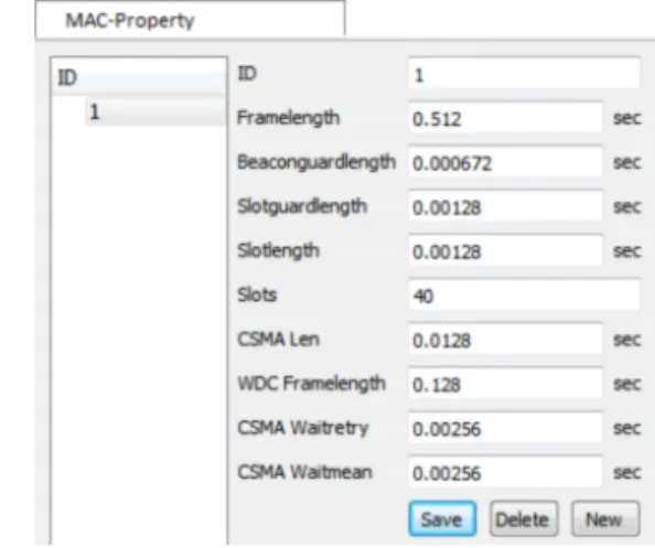
D. Configuration and Visualization Plugin
Several configuration and visualization plugins were nec-essary for the required functions of our example application. Figure 5 shows the configuration dialog for the MAC layer as an example. Moreover, a 3D view with depicting physical positions of system components is created based on the OpenGL library.
Fig. 5. Configuration plugin to edit the structure of the MAC layer.
To analyze the simulation results, different visualization plu-gins such as delay analysis or error rate analysis are developed. These plugins use the Qwt graph library. Its Qwt graph widget is encapsulated into a widget plugin. The visualization plugin asks the microkernel for a new instance of the graph widget and fills this widget with the simulation results.
Simulation results are usually preprocessed first. Therefore, components to calculate the minimum, maximum, mean value, and so on are implemented applying the wrapper pattern [14]. Visualization of limits such as maximum delay is implemented as well.
Figure 6 shows the visualization plugin for mean package end-to-end delay as an example. Green and blue lines depict mean package delay of different applications. For the blue line the standard deviation are visualized additionally. The horizontal red line specifies the delay limit, and vertical lines separate different flight phases. There are two different appli-cations using TDMA or CSMA slots. Application results and analyzed components could be selected with the corresponding drop down box.
The selected results will be preprocessed in a different way. It is possible to use the raw values or to add up the result values. Based on these values it is possible to calculate the mean value, the standard deviation and the minimum and maximum value. The type of presentation can be configured with an additional property dialog.
This graph view is a common widget which is encapsulated in a widget plugin and is reused by other result analysis.
Fig. 6. Example of a visualization plugin to analyze the end-to-end delay of messages, by using the modelled wireless sensor network.
To realize this application, a fast prototype of the model and the simulation-based application are developed. This pro-totype was enhanced iteratively by additional components with detailed or new simulation features and result analyses. The following section describes this agile software development process for simulation-based applications in detail.
V. ANAGILESOFTWAREDEVELOPMENTPROCESS
The presented framework enables separate development of simulatable system models, the implementation of simulation based application components, and the optimization of sys-tem parameters by using rapidly prototyped simulation-based applications.
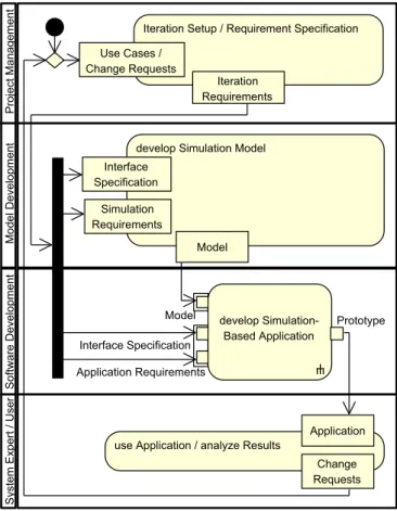
Figure 7 visualizes the activities of this agile software devel-opment process. Contrary to common software develdevel-opment processes (see Figure 1), model and software development may run in parallel. A precondition for this is the definition of additional interface specifications. This mainly includes the database specifications for the configuration and result database. After a fast prototype is already developed, the sys-tem expert can validate the results of the simulation using the simulation-based application directly. Database specifications, model and software are refined iteratively afterwards in fast iteration cycles.
The advantages of agile software development process are well known [4], [15], [16]. Additionally, in this case the system expert can work directly with the simulation-based system design tool. Software errors will thus be found earlier, while bug fixes, useful enhancements or additional change requests can be integrated into the tool at early stages of product development. Moreover, the presented framework supports easy reuse of the developed components.
Proj ectqManage ment Model qDevelopm ent Software qDevelopm ent SystemqExp ertq/qUser IterationqSetupq/qRequirementqSpecification Iteration Requirements UseqCasesq/ ChangeqRequests developqSimulationqModel Interface Specification Model Simulation Requirements developqSimulation-BasedqApplication useqApplicationq/qanalyzeqResults Application Change Requests Prototype ApplicationqRequirements InterfaceqSpecification Model
Fig. 7. Simplified agile software development process for simulation-based applications based on the presented framework.
VI. CONCLUSION
This paper presents a programming framework for simu-lation-based applications. It separates the development of a base model, the implementation of simulation application components, and the optimization system parameters from each other.
Therefore it is possible to develop these parts in parallel. This allows an agile, evolutionary, iteratively and simulation-based software development process. Existing components can be reused easily, and the programming effort for user-friendly system design tools is significantly decreased.
Besides the modeling and software development tasks, the definition of the content of the configuration and re-sult database, the definition of conditions and dependencies between this database elements and the design of the GUI are still major tasks for the development of simulation-based applications.
The advantages of model-driven engineering can be used to simplify these tasks. The database structure can be generated by using entity relationship diagrams or UML class diagrams with the aid of qualified associations. To create configuration plugins in an easier way, a graphical dialog editor could be used. Therefore, common components to edit different types of configuration data such as integer, string, list, and so on will be needed. To define the conditions and dependencies
between configuration entities, the object constraint language (OCL) [17] and the parametric diagram [18] can be used. Moreover, it is possible to use UML behavior diagrams, like the activity diagram, to describe the preprocessing of the simulation results. All these enhancements are subject of actual and future developments.
REFERENCES
[1] P Benjamin, K. Akella, A. Verma, B. Gopal, and R. Mayer, “A knowledge-driven framework for simulation application integration,” Journal of Simulation, no. 5, pp. 166–189, 2011.
[2] Xiaolin Hu, “A simulation-based software development methodology for distributed real-time systems,” Ph.D. dissertation, THE UNIVERSITY OF ARIZONA, Tucson, 2004. [Online]. Available: http://www.imamu. edu.sa/Scientific selections/Documents/IT/Xiaolin dissertation.pdf [3] D. L. Parnas, A rational design process; how and why to fake it.
Washington: Computer Science and Systems Branch, 1985.
[4] T. Stober and U. Hansmann,Agile software development: Best practices for large software development projects. Berlin: Springer, 2010. [5] I. Sommerville, Software engineering, 9th ed. Boston and Mass:
Pearson, 2011.
[6] A. Agarwal, C.-D. Iskander, R. Shankar, and G. Hamza-Lup, “System-level modeling environment: MLDesigner,” inIEEE Int. Systems Conf. (SysCon 2008), Montreal, Canada, April 2008.
[7] G. Schorcht, P. Unger, A. George, I. Troxel, D. Zinn, H. Salzwedel, K. Farhangian, and C. Mick, “System-level simulation modeling with MLDesigner,” in11th ACM / IEEE Int. Symp. on Modeling, Analysis and Simulation of Computer and Telecommunication Systems (MASCOTS), 2003.
[8] T. Baumann, A. Pacholik, and H. Salzwedel, “Performance exploration with MLDesigner using standardised communication interfaces,” in Proceedings of the DATE ’07, 2007.
[9] F. Buschmann, Pattern-oriented software architecture: A system of patterns, volume 1. Chichester and and New York: Wiley, 1996. [10] Object Management Group. Unified Modeling Language (UML).
[Online]. Available: http://www.uml.org/
[11] Microsoft, “Microsoft odbc application programmer’s guide,” 1994. [12] Sven J¨aeger, Tino Jungebloud, Ralph Maschotta, and Armin
Zimmer-mann, “Model-based QoS evaluation for embedded wireless sensor net-works,” inProc. IEEE International Systems Conference (SYSCON’13), Orlando, Florida USA, Apr. 2013, pp. –, submitted.
[13] MLDesign Technologies. Mldesigner. [Online]. Available: http://www. mldesigner.com
[14] Erich Gamma, Richard Helm, Ralph Johnson, and John Vlissides, De-sign patterns: Elements of reusable object-oriented software. Reading and Mass: Addison-Wesley, 1995.
[15] A. Cockburn, Agile software development: The cooperative game, 2nd ed., ser. The Agile software development series. Upper Saddle River and NJ: Addison-Wesley, 2009.
[16] J. Highsmith,Agile software development ecosystems, 3rd ed., ser. The Agile software development series. Boston and Mass: Addison-Wesley, 2006.
[17] Object Management Group. Object Constraint Language (OCL). [Online]. Available: http://www.omg.org/spec/OCL/
[18] ——. System Modeling Language (SysML). [Online]. Available: http://www.omg.org/spec/SysML/