AFP710 Fire Repeater Panel
Installation Instructions
_________________________________________________________________________________________________ 1 2 3 4 5 6 7 8 9 10 11 -1-2 3-4 1-32These instructions explain how to install an AFP710 Repeater Panel. Repeater Commissioning details can be found in the main AFP Installation & Commissioning Instructions. For operating instructions please refer to the AFP User Instructions/Log Book.
Fire alarm system design is beyond the scope of this document. A basic level of understanding of general fire alarm system components and their use is assumed.
This equipment is not guaranteed unless the complete installation is installed and commissioned in accordance with the laid down national standards (in the UK BS 5839: Pt 1: 1988) by an approved and competent person or organisation.
This equipment must only be installed and maintained by a suitably skilled and technically competent person. This equipment is a piece of Class 1 equipment and MUST BE EARTHED
No responsibility can be accepted by the manufacturer or distributors of this product for any misinterpretation of an instruction or guidance note or for the compliance of the system as a whole.
The manufacturers policy is one of continuous improvement and we reserve the right to make changes to product specifications at our discretion and without prior notice. E&OE.
_________________________________________________________________________________________________ Approved Document No. DFU0711003 Rev 1
1
GENERAL
This repeater panel is designed to work with the AFP Range of Analogue Addressable Fire Panels.
It is fully compliant with the statutory requirements of EN60950 (LVD) and EN50130-4 (EMC) and includes an integral monitored PSU and an independent battery back-up supply to ensure the Master Panel’s PSU and stand-by batteries are not compromised.
One AFP711 Network Driver Card is required per system. This should be fitted to the RS485 port on the AFP Master Panel’s main control PCB. Once fitted, the Network Driver Card allows the connection of up to 15 Repeaters per system. Installation Instructions for the AFP711 are provided on a separate instruction sheet supplied with the Network Driver Card (Document No. DFU0711000).
All Access Level 1 functions and virtually all Access Level 2 functions (except date and time setting, Access Level 2 code changing and event log printing) are available at Repeaters. Therefore the AFP User Instructions which are supplied with the Master Panel (Document No. DFU07001002) also apply to Repeaters.
All Access Level 3 engineering and commissioning functions are available at Master Panels only. These functions are detailed in the main AFP Installation & Commissioning Instructions (Document No. DFU0701001).
The only set of instructions which should be left for the user are the AFP User Instructions.
This Repeater is not compatible with AFP Master Panels with a MAIN software revision number of 2A47 or earlier. To ascertain the software revision number of an AFP Master Panel, please refer to the main AFP Installation and Commissioning Instructions.
2
INSTALLATION
2.1
Repeater Panel Location
The panel MUST be sited internally and MUST NOT be subject to conditions likely to affect its performance e.g. damp, salt-air, water ingress, extremes of temperature, physical abuse etc. The panel should be sited at a height where it is easily accessible and in a prominent position within the building. This means in most situations that the LCD should be at eye level.
2.2
Mounting the Enclosure
The panel is supplied with a hinged lid; a metal back box and three separate PCBs. The relative location of these PCBs is indicated below:
Power & Control PCB LCD
Front Panel Switch and Indicator PCB
PCB Retaining Screw Lid earth strap
Chassis earth point
PSU earth strap
PL1 Lid earth point
The panel can be surface or semi-flush mounted. To expose the base mounting holes, the base PCB must first be removed. It is also recommended that the hinged lid be removed to prevent accidental damage during the fixing process.
1) Take the panel out of its box and undo the two screws on the right hand side of the lid using the Allen key
provided.
2) Hinge the lid 180° to the left (do not overbend the hinges). On metal lidded panels only, remove the lid
earth strap from the base earth connection (plastic lidded panels do not require a lid earth strap).
3) Disconnect the lid/base connecting cable (PL1) from the Power & Control PCB in the repeater base. Care
should be taken when detaching this connector to depress the telecoms-style locking tab to prevent damage.
4) Carefully remove the four M4 retaining nuts which secure the hinges. To remove the repeater’s base Power & Control PCB:
-5) Ensure power has been removed from the panel and that the base PCB is safe to handle. 6) Pull the PSU earth strap off the spade connector at the main chassis earth point.
7) Carefully undo the PCB retaining screw located at the bottom left hand side of the PCB using a crosshead
screwdriver.
8) Push the PCB upwards and then pull forwards over the mounting pillars taking care not to damage any of
the components.
The panel lid and base Power & Control PCB can now be removed from site to prevent accidental damage. Please note: PCBs are static-sensitive and we strongly advise that relevant anti-static handling
precautions are observed when handling them. Refer to Appendix 1 for further details.
9) Decide carefully how the wiring will be brought into the panel with reference to figure 1 below and
Sections 2.3 and 2.4 later in this document.
10) Remove the required knock-outs for cable entry. Always ensure if a knock-out is removed, the hole is
filled with a good quality cable gland. Any unused knock-outs must be securely blanked off. It is essential that the 230Va.c. mains cable comes into the enclosure via one of the inlets at the top right hand corner of the enclosure.
11) Using the four mounting holes, fix the base securely onto/into the wall. The mounting holes are suitable
for use with No.8 roundhead or countersunk woodscrews. Assess the condition and construction of the wall and use a suitable screw fixing. Any dust or swarf created during the fixing process must be kept out of the fire panel and great care must be taken not to damage any wiring or components.
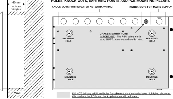
Figure 1 : Semi-Flush Mounting of AFP Repeater and Internal View of Panel Back Box
INTERNAL VIEW OF BACK BOX (WITH PCBS REMOVED) SHOWING MOUNTING HOLES, KNOCK-OUTS, EARTHING POINTS AND PCB MOUNTING PILLARS
KNOCK-OUTS FOR MAINS SUPPLY KNOCK-OUTS FOR REPEATER NETWORK WIRING
60mm includes 'dimples' DIAGRAM TO SHOW SEMI-FLUSH MOUNTING OF AFP REPEATER WALL
CHASSIS EARTH POINT
IMPORTANT: The PSU safety earth strap MUST be connected to this point. MOUNTING HOLE MOUNTING HOLE MOUNTING HOLE MOUNTING HOLE
2.3
230V a.c. Mains Wiring
Please note: These guidelines are based on BS 5839: Pt1: 1988 and BS 7671 (Wiring Regulations). Other national standards of installation should be used where pertinent.
It is important that mains is brought into the enclosure at the top right hand side as indicated in Figure 2 below. The equipment must have fixed wiring, using three core cable (no less than 0.75mm2 and no more than 2.5mm2) or a suitable three conductor system, fed from an isolating switch fused spur, fused at 3A. This
should be secure from unauthorised operation and be marked “FIRE ALARM: DO NOT SWITCH OFF”. This mains supply must be exclusive to the repeater panel.
Correctly terminate the incoming cables to the Repeater’s power & control PCB as shown in Figure 2 below. If required, the 5mm connector block (CONN2) can be pulled from the PCB for ease of installation.
Ensure that the incoming mains earth is connected directly to this connector block and NOT to the chassis earth point. (The PSU earth strap must be connected to the chassis earth point before operation).
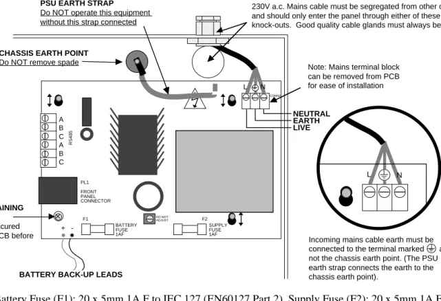
Figure 2 : Mains Connection to Repeater Power & Control PCB.
230V a.c. Mains cable must be segregated from other cables and should only enter the panel through either of these two knock-outs. Good quality cable glands must always be fitted.
CHASSIS EARTH POINT
Do NOT remove spade
L N
SUPPLY FUSE 1AF
+
-BATTERY BACK-UP LEADS
L N
Incoming mains cable earth must be connected to the terminal marked and not the chassis earth point. (The PSU earth strap connects the earth to the chassis earth point).
LIVE EARTH NEUTRAL
DO NOT ADJUST
PSU EARTH STRAP
Do NOT operate this equipment without this strap connected
Note: Mains terminal block can be removed from PCB for ease of installation
PCB RETAINING SCREW Must be secured tightly to PCB before operation PL1 FRONT PANEL CONNECTOR A B C A B C RS485 CONN2 BATTERY FUSE 1AF F1 F2
Fuses: Battery Fuse (F1): 20 x 5mm 1A F to IEC 127 (EN60127 Part 2). Supply Fuse (F2): 20 x 5mm 1A F to
IEC 127 (EN60127 Part 2). Do not use any other type or size of fuse in these positions.
PCB Retaining Screw: Do not operate this equipment without this screw secured tightly to the PCB as it
plays an important part in the electrical safety and EMC immunity of this product.
Battery back-up leads: These MUST be connected to two 12V VRLA (sealed lead acid) batteries as shown
in the diagram below. For 24 hours stand-by time use two x 12V 2.1AHr VRLA batteries connected in series. For 72 hours stand-by time use two x 2.8AHr batteries connected in series. It should be noted that repeater panels will not start on batteries alone, i.e. mains must be connected.
Red wire from PSU Black wire from PSU
12V 12V + + – –
Repeaters should be wired in a daisy chain formation using fireproof cable of at least 1mm2 c.s.a. (i.e. PYRO™, FP200™ or comparable). Do not star or spur. End termination devices are not required and no priority need be given to the location of the Master Panel in the daisy chain, i.e. it can be wired anywhere on the Repeater network. The total cable length for the Repeater network should not exceed 1KM. Please refer to the typical Repeater network wiring diagram (Figure 3)
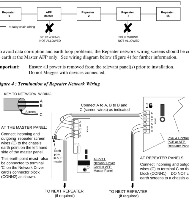
below:-Figure 3 : Typical Repeater Network Wiring
Repeater 1 AFP Master Repeater 2 Repeater 5 Maximum distance = 1 KM
✘
SPUR WIRING NOT ALLOWED Repeater 15✘
SPUR WIRING NOT ALLOWED = daisy chain wiringTo avoid data corruption and earth loop problems, the Repeater network wiring screens should be connected to earth at the Master AFP only. See wiring diagram below (figure 4) for further information.
Important: Ensure all power is removed from the relevant panel(s) prior to installation. Do not Megger with devices connected.
Figure 4 : Termination of Repeater Network Wiring
RS485 A B C A B C PL1 RS485 A B C A B
AT THE MASTER PANEL: Connect incoming and outgoing repeater screen wires (C) to the chassis earth point on the left hand side of the master panel. This earth point must also be connected to terminal 'C' on the Network Driver card's connector block (CONN2) as shown.
Connect A to A, B to B and C (screen wires) as indicated
TO NEXT REPEATER (if required) TO NEXT REPEATER (if required) AFP711 Network Driver Card at AFP Master Panel
PSU & Control PCB at AFP Repeater Panel
AT REPEATER PANELS:
Connect incoming and outgoing screen wires (C) to terminal C on the connector block (CONN1). DO NOT connect the earth screens to a chassis earth point.
NOTE: loop connection terminal blocks can be removed from the PCBs for ease of installation
A B C
Screen
KEY TO NETWORK WIRING
Earth point in AFP master
2.5
Setting a Repeater’s Address and Segment Number
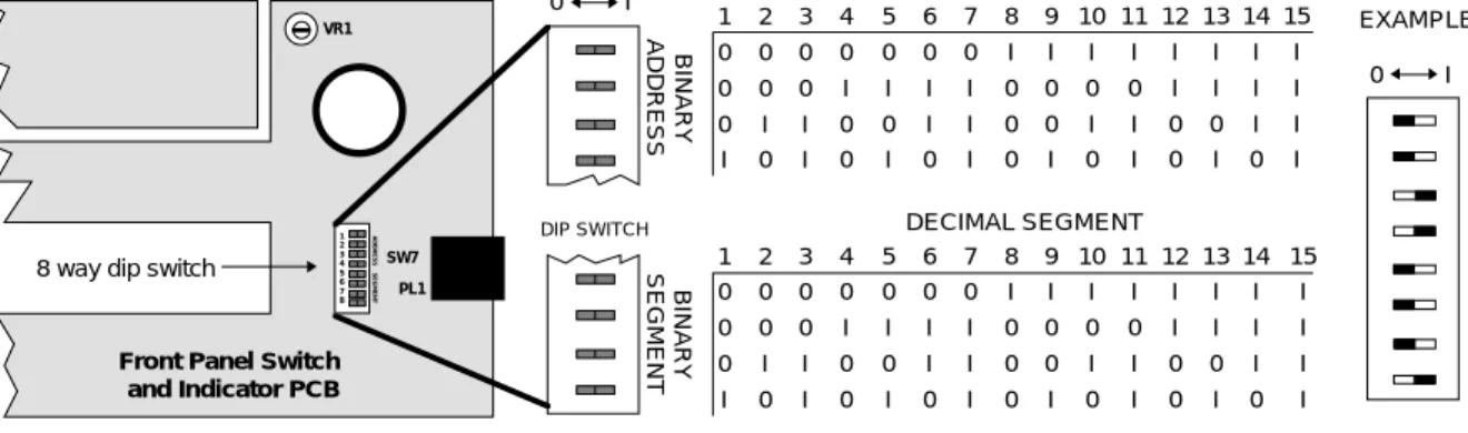
The Repeater’s address and Segment number is required for commissioning purposes and can be set using the 8 way Dip Switch located on the Repeater’s Front Panel Switch and Indicator PCB (see Figure 5 below).
Address Number:
Up to 15 repeaters can be connected to one AFP master panel and each Repeater must have a unique address number set between 1 and 15. Adjust the switches labelled ADDRESS as appropriate to give each Repeater
it’s own individual address (options available are highlighted in Figure 5 below). Note that address 0 must not be used and that addresses do not have to run sequentially, i.e.Repeater 5 can be connected to Repeater 10.
Segment Number:
The switches labelled SEGMENT are used for setting the Repeater’s ‘Segment’ number. The Segment number of all Repeaters must be the same as the Master Panel’s Segment number (this is set to 1 by default). The Master Panel’s Segment number can be changed via an Access Level 3 menu. Different Segment numbers will not be required until the AFP’s panel multiplexing facility is available at a later date. Segment number 0 must not be used.
Figure 5 : Repeater address switch location and setting details
1 0 0 0 I 2 0 0 I 0 3 0 0 I I 4 0 I 0 0 5 0 I 0 I 6 0 I I 0 7 0 I I I 8 I 0 0 0 9 I 0 0 I 10 I 0 I 0 11 I 0 I I 12 I I 0 0 13 I I 0 I 14 I I I 0 15 I I I I DIP SWITCH VR1 SW7 PL1 1 2 3 4 5 6 7 8
Front Panel Switch and Indicator PCB
8 way dip switch
BINARY ADDRESS BINARY SEGMENT 0 I 1 0 0 0 I 2 0 0 I 0 3 0 0 I I 4 0 I 0 0 5 0 I 0 I 6 0 I I 0 7 0 I I I 8 I 0 0 0 9 I 0 0 I 10 I 0 I 0 11 I 0 I I 12 I I 0 0 13 I I 0 I 14 I I I 0 15 I I I I ADDRESS SEGMENT ADDRESS SEGMENT 0 I = 3
}
= 1}
EXAMPLE DECIMAL ADDRESS DECIMAL SEGMENT3 REPEATER PANEL OPERATION
All Access Level 1 and virtually all Access Level 2 functions (except date and time setting, Access Level 2 code changing and event log printing) are available at Repeaters. Other than these few exceptions, from a user’s point of view the AFP Repeater panel operates in exactly the same way as the AFP Master. Therefore, the AFP User Instructions (Document No. DFU07001002) should be referred to with regard to the operation of this equipment.
Notes:
1/ Only one person can enter Access Level 2 at any one time.
2/ Access Level 3 (Engineer/Programming functions) can be entered at AFP Master panels only. 3/ Repeater-related faults that will result in fault messages are:
(a) a repeater address or segment number of 0.
(b) a breakdown of communication between Repeater and Master.
4 OVERVIEW OF REPEATER COMMISSIONING PROCEDURE
Outlined below is an overview of the recommended procedure for commissioning AFP Repeater Panels. Remember to disconnect all power before commencing.
1) Ensure the Network Driver Card has been correctly fitted to the master panel and that all repeaters have been installed and wired as shown in these instructions.
2) Set the Repeater’s address and segment number as highlighted in these instructions. 3) Power up the Master and Repeater panels. (Repeaters cannot be started on batteries alone). 4) Ensure the Master Panel’s Segment Number is set to the same as the Repeater(s)*
5) Name the Master Panel (if you do not wish to keep its default name)* 6) Learn Network Devices*
7) Name Repeaters (if you do not wish to keep their default names)*
* To complete steps 4, 5, 6 and 7 you will need to gain entry to the AFP’s Access Level 3 Programming Menus. This can be done at AFP master panel only. Please refer to the AFP Installation & Commissioning Instructions (Document No. DFU0701001) for full details.
Before handling PCBs or any other static-sensitive components, operators should rid themselves of any personal electro-static charge by momentarily touching any of the earth studs in the AFP’s metal back box with all circuit boards and connections correctly in place. This should be done immediately prior to handling the sensitive components. If not in the vicinity of the back box, any other sound connection to safety earth may be touched. Static sensitive items may now be handled with care. Important: DO NOT touch the legs of any component and always handle PCB’s by their sides.
PCBs should be stored in a clean, dry place which is free from vibration, dust and excessive heat. Retaining the PCBs in a suitable cardboard box will also guard them against mechanical damage.