Re v. 06-20 11
5
TERMOREGOLATORI
5
TEMPERATURE CONTROLLERS
INTRODUZIONE - INTRODUCTION:
I termoregolatori permettono, tramite l'impostazione del valore di temperatura desiderata (set-point), di controllare e di mantenere costante il valore prefissato della temperatura dell'elemento riscaldante confrontando il valore rilevato dal sensore con quello impostato dall'utilizzatore.
I termoregolatori EL.CO. possono essere di tipo analogico o a microprocessore. In particolare gli strumenti a microprocessore, grazie alla facilità ed alla flessibilità della programmazione dei parametri, offrono un'ampia possibilità di regolazione della temperatura. Molti di questi strumenti dispongono, oltre alla regolazione PID anche della funzione di AUTOTUNING che permette di calcolare automaticamente i parametri di regolazione.
La maggior parte degli strumenti a microprocessore hanno la possibilità di utilizzare, come segnali di ingresso per il controllo della temperatura, oltre le tradizionali sonde a termocoppia o a termoresistenza, anche segnali analogici in corrente o in tensione e tramite la funzione di HEATER BREAK sono in grado di rilevare eventuali guasti o interruzioni dell'elemento riscaldante.
La flessibilità alle più svariate applicazioni dei termoregolatori EL.CO. è facilmente riscontrabile anche dal numero e tipologia di uscite, sia principali che ausiliarie, di cui ognuno di essi dispone.
L'uscita principale viene impiegata per il mantenimento della temperatura impostata ed ad essa vengono abbinate uscite secondarie che vengono usate per segnalare allarmi, interruzione dell'elemento riscaldante, fasi di raffreddamento o riscaldamento ecc. Il tipo di intervento e la modalità di commutazione delle uscite viene stabilita al momento della programmazione del termoregolatore.
Temperature controllers allow, through temperature desired value's statement (set-point), to check and to keep the temperature prearranged value of the warming element steady, comparing the value pointed out by the sensor with the one adopted by the user.
Elco temperature controllers can be analogue or microprocessor-based type.
Particularly microprocessor-based tools, thanks to easiness and flexibility of parameters' planning, offer a wide possibility of temperature's adjustment. A lot of these instruments have, besides PID control, also the AUTOTUNNING function which allow to calculate regulation parameters automatically. Most of microprocessor based tools can use, as input signals for temperature's control, besides traditional thermocouple or thermoresistance probes, also analogue signals in current or in voltage and through HEATER BREAK function can point-out incidental failures or interruptions of the warming element.
Flexibility to various applications of ELCO temperature controllers is easily verifiable also from the number and typology of outputs, both principal and auxiliary that they have.
The main output is used for keeping the layed out temperature and it's coupled with secondary outputs used to signal alarms, interruption of the warming element, heating or cooling phases, etc.
The type of intervention and modalities of output's switchover are fixed at the moment of temperature controller's programming.
TIPI DI REGOLAZIONE - TYPES OF REGULATION
I tipi di regolazione che i termoregolatori possono effettuare sono le seguenti: regolazione ON-OFF :
regolazione della temperatura semplice e relativamente lenta molto sensibile alla variazioni di alimentazione o di carico. L'uscita è in condizione ON per temperature più basse del valore prefissato (set point) mentre è in condizione OFF per temperature più alte.
regolazione "P" (proporzionale) :
questo tipo di regolazione viene adottata quando si vuole eliminare l'isteresi della temperatura sull'elemento riscaldante caratteristica della regolazione ON-OFF.
In tal senso l'utilizzatore definisce due temperature (banda proporzionale) che comprendono il set-point dove la regolazione della temperatura viene effettuata con continuità secondo un tempo denominato ciclo proporzionale (duty cicle) all'interno del quale variano i tempi di ON e di OFF dell'uscita. Questo tipo di regolazione permette una buona stabilità della temperatura ma è caratterizzata da una differenza della stessa rispetto al valore di set-point (offset).
regolazione "PD" (proporzionale-derivata) :
la regolazione proporzionale derivata in aggiunta alla regolazione "P" permette di effettuare un rapido ritorno al valore di set-point al verificarsi di una rapida variazione di temperatura dovuta a forti disturbi esterni.
regolazione "PID" (proporzionale-integrata-derivata) :
la regolazione (PID) permette il controllo della temperatura con l'impiego contemporaneo dell'azione "PD" più l'azione integrale "I" con la quale si può eliminare automaticamente l'offset di temperatura tipico della regolazione proporzionale.
auto-tuning :
la funzione di auto-tuning permette al termoregolatore, tramite un ciclo di autoapprendimento, di calcolare automaticamente tutti i valori ottimali dei parametri dell'azione "PID" in base alle caratteristiche dell'elemento da dover riscaldare.
Types of regulation that temperature controllers can realized are:
ON - OFF regulation:
simple and fairly slow temperature adjustment, very sensitive to power-supply or load variations. Output is ON state for temperature lower than prearranged value (set-point), whereas it's OFF state for higher temperature.
"P" regulation (proportional) :
this type of adjustment is adopted when we want remove temperature's hysteresis on the warming element typical of ON - OFF regulation.
In this sense user defines two temperatures (proportional band) which include set-point, where the temperature's regulation is carried out with continuity in conformity with a time called proportional cycle (duty cycle) during which output's ON and OFF times change. This type of adjustment allow a good temperature's steadiness but it's characterized from a temperature's difference as regards set point's value (offset).
"PD" regulation (proportional-derivative) :
Proportional - derivative regulation with the addition of "P" regulation allow to make a quick return to set-point value in case of a rapid variation of temperature caused by strong exterior troubles.
"PID" regulation (proportional-integrated-derivative) :
PID regulation allow temperature's control using at the same time PD action and the integral "I" action with whom we can remove the temperature's offset typical of the proportional regulation automatically.
auto-tuning :
auto-tuning function allow to temperature controller, throught a selflearning cycle, to calculate automatically all optimal values of PID action's parameters basing on characteristics of element to warm.
Rev.
06
-2
01
1
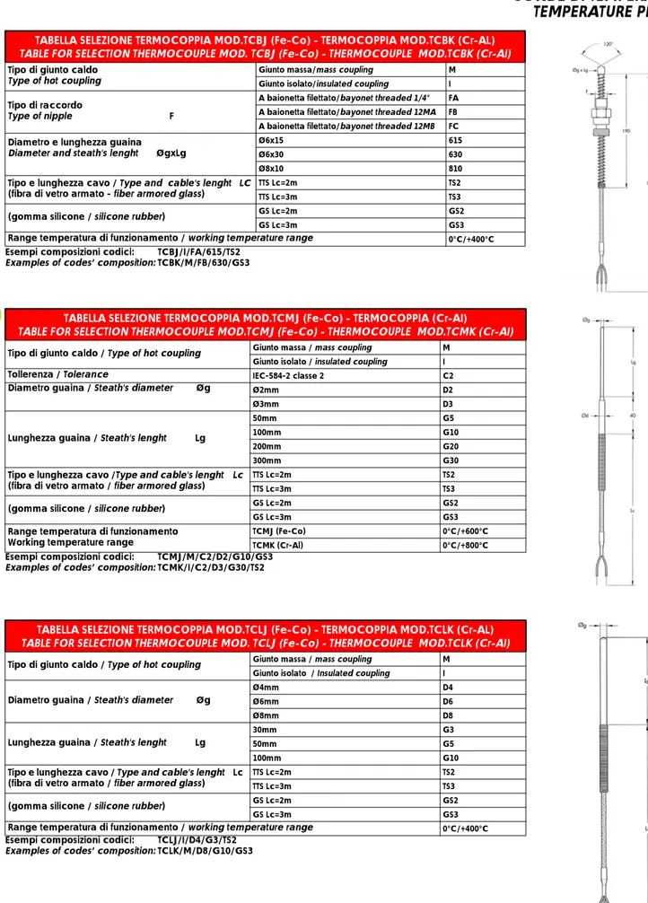
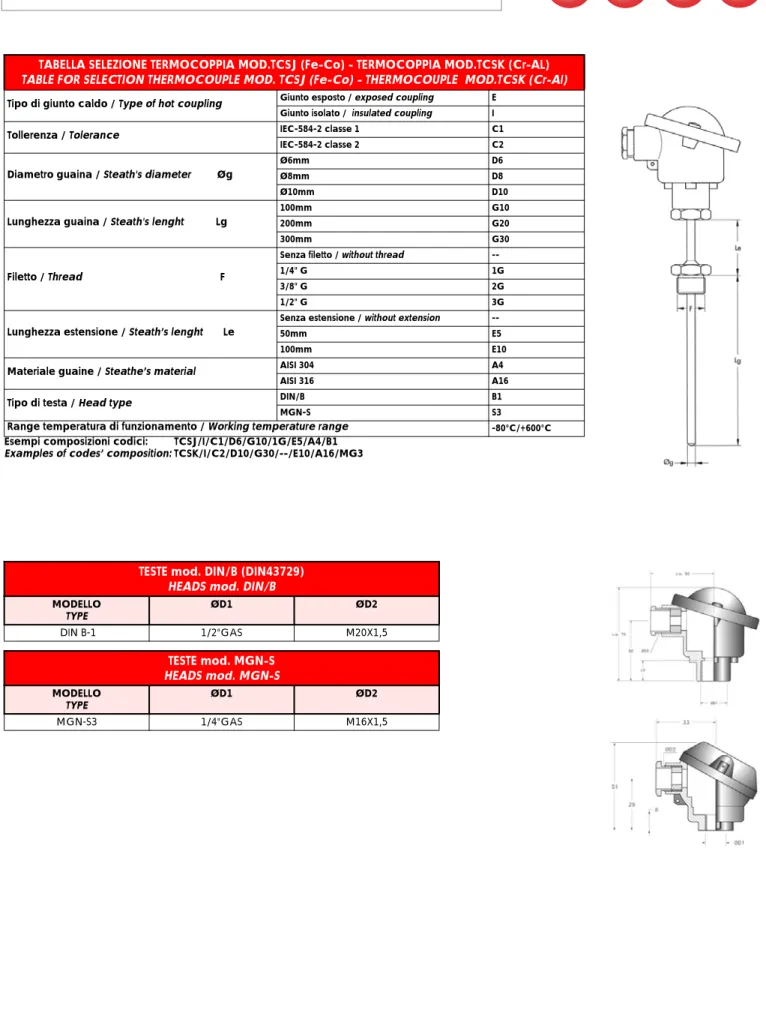
SONDE DI TEMPERATURA - TEMPERATURE PROBES:
Come supporto ai propri termoregolatori la ditta EL.CO. può fornire una completa gamma di sonde di temperatura.
Tipi di sonde disponibili:
a. Termocoppie (tipo J,K,S,R,T, ecc)
range di temperatura: sino a 1800 °C - classe di precisione: 1 o 2 - normative di riferimento: IEC 584-2 b. Termoresistenze (tipo Pt100 o Ni 100)
range di temperatura: da -200 °C a +850 °C - classe di precisione: A o B - normative di riferimento: IEC 571 c. Termistori (tipo PTC KTY 81)
range di temperatura: da -50 °C a +150 °C
Tutte le sonde sono inoltre disponibili in più configurazioni, con diversi formati, puntali e tipi di cavi anche su specifica del cliente.
As support at its own temperature controllers, the company ELCO can supply a complete range of temperature probes.
a. Thermocouple (J,K,S,R,T type, etc.)
temperature range: til 1800 °C - class of accuracy: 1 or 2 - reference regulations: IEC 584-2 b. Thermoresistance ( Pt100 or Ni 100)
temperature range: from -200 °C to +850 °C - class of accuracy: A or B - reference regulations: IEC 571
c. Thermistor (PTC KTY 81 types)
temperature range: from -50 °C to +150 °C
All probes are moreover available in different shapings, formats, prods and types of cables also on customer's specification.
Re
v.
06-20
11
TERMOREGOLATORI ELETTRONICI ANALOGICI E DIGITALI
ANALOGUE AND DIGITAL ELECTRONIC TEMPERATURE CONTROLLERS
SERIE E48-AN pag. 4
E48-AN SERIES pag. 4
REGOLATORI A MICROPROCESSORE SERIE ELK 4 pag. 6
ELK 4 MICROPROCESSOR BASED REGULATORS SERIES pag. 6
REGOLATORE A MICROPROCESSORE SERIE ELK72 pag. 10
ELK75 MICROPROCESSOR BASED REGULATORS pag. 10
SERIE ELK94-ELK94S pag. 13
ELK94-ELK94S SERIES pag. 13
REGOLATORE A MICROPROCESSORE SERIE ELK35 pag. 10
ELK35 MICROPROCESSOR BASED REGULATORS pag. 10
REGOLATORE A MICROPROCESSORE SERIE ELK96 pag. 10
ELK96 MICROPROCESSOR BASED REGULATORS pag. 10
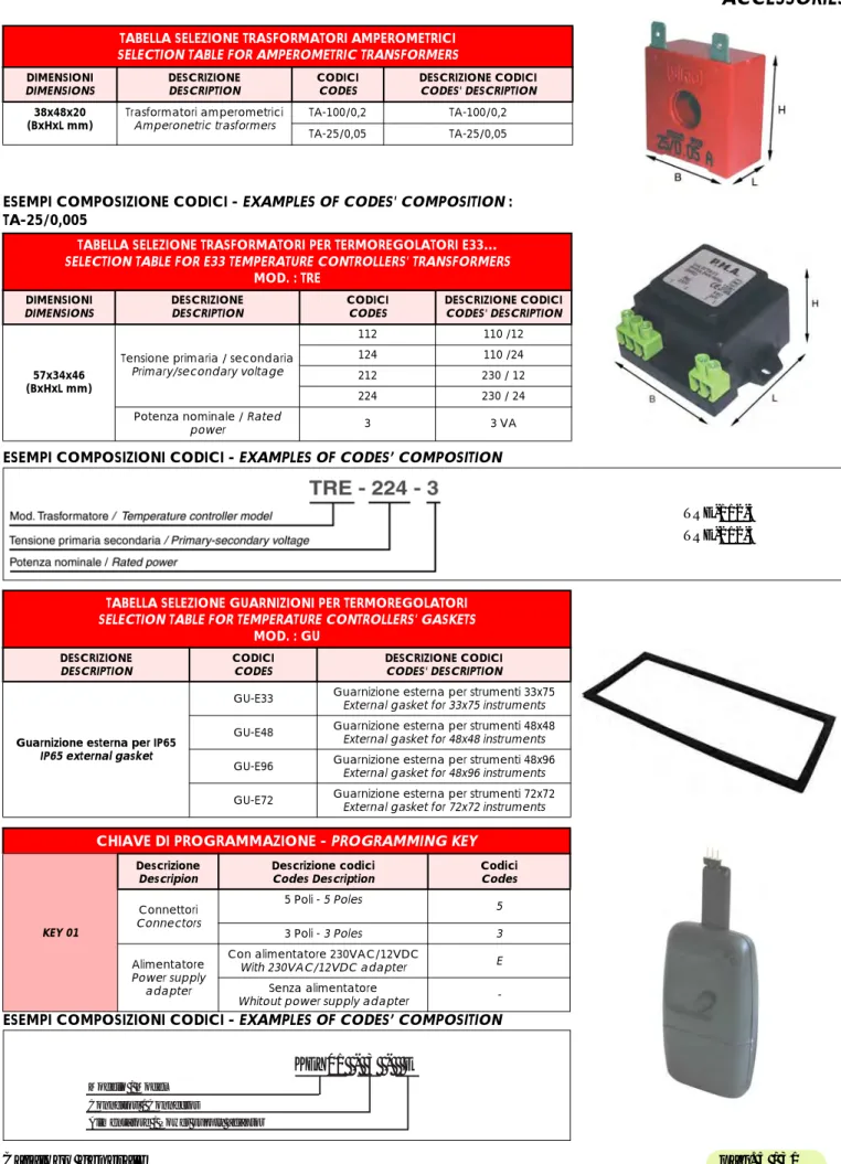
ACCESSORI pag. 31
ACCESSORIES pag. 31
SONDE DI TEMPERATURA pag. 40
Rev. 06 -2 01 1
SERIE E48-AN
E48-AN SERIES
DATI TECNICI -TECHNICAL DATA
Alimentazione / Power supply 24, 110, 230 VAC +/- 10% f: 50/60 Hz Assorbimento / Power consumption 3 VA circa / 3 VA approx
Ingresso/i / Input(s) 1 ingresso per sonde di temperatura tc J, tc K, Pt 100 IEC 1 input for temperature probes tc J, tc K, Pt 100 IEC
Uscita/e / Output(s) 1 uscita a relè (8A/250V AC1) o in tensione per pilotaggio SSR (12 VDC/20 mA) 1 relay (8A/250V AC1) or voltage output for SSR drive (12 VDC/20 mA)
Contenitore / Case plastico autoestinguente, UL 94 VO
self-extinguishing plastic, UL 94 VO Dimensioni / Dimensions frontale DIN 48 x 48 mm, profondità 89 mm
front panel DIN 48 x 48 mm, depth 89 mm Installazione / Mounting a pannello in foro 45,5 x 45,5 mm
flush in panel in 45,5 x 45,5 mm hole
Connessioni / Connections zoccolo OCTAL
OCTAL - 8 pins socket Grado di protezione frontale
Degree of protection of front panel IP 54, montato a pannello con guarnizioneIP 54, mounted on the panel with seal
Regolazione/ Control ON/OFF o Proporzionale
ON/OFF or Proportional
Funzionamento / Operation ON/OFF con isteresi di 3 °C e Proporzionale con banda di 10 °C e tempo di ciclo di 25 sec. ON/OFF with 3 °C hysteresis, and proportional with 10 °C and 25 sec. cycle time
Range di misura
Measurement range secondo la sonda utilizzata e la scala scelta. Scale disponibili da -50 °C a 1200 °C. according to the used probe and the chosen scale. Scales available from -50 °c to 1200 °C Precisione totale / Overall accuracy tc: +/- 2% fs, Pt100: +/- 1% fs
Conformità / Compliance Direttiva CEE EMC 89/336 (EN 50081-1, EN 50082-1), Direttiva CEE BT 73/23 e 93/68 (EN 60730-1) EEC directive EMC 89/336 (EN 50081-1, EN 50082-1), EEC directive LV 73/23 and 93/68 (EN 60730-1) TABELLA SELEZIONE TERMOREGOLATORI - TEMPERATURE CONTROLLER SELECTION TABLE
EL.CO MOD.: E48-AN
DIMENSIONI / DIMENSIONS DESCRIZIONE / DESCRIPTION CODICI / CODES DESCRIZIONE CODICI / CODES’ DESCRIPTION
DIN 48X48
ALIMENTAZIONE / POWER SUPPLY
24 A 24VAC
110A 110VAC
230A 230VAC
24/240 24...240 VAC
SEGNALE INGRESSO / INPUT SIGNAL
J TERMOCOPPIA/ THERMOUCOUPLE J
K TERMOCOPPIA/ THERMOUCOUPLE K
P TERMORESISTENZA / THERMORESISTANCE Pt1001
USCITA / OUTPUT R RELE’ / RELAY
S 12VDC X SSR
TIPO DI REGOLAZIONE / TYPE OF CONTROL O ON/OFF
P PD SCALE TEMPERATURA TEMPERATURE SCALE 0...100°C 0...200°C 0...350°C 0...600°C 0...800°C 0...1000°C 0...1200°C 0...250°C
* 1 ingresso per sonde di temperatura TC J, TC K, Pt 100 * 1 input for temperature probes TC J, TC K, Pt 100 * 1 uscita a relè o in tensione per SSR
* 1 relay or voltage for SSR output * Regolazione on/off o proporzionale * On/ off or proportional control * Connessioni octal
* Octal - 8 pins socket connections * 10 scale disponibili da -50 °C a 1200 °C * 10 scales available from -50 °C to 1200 °C
Re
v.
06-20
11
ESEMPI COMPOSIZIONI CODICI - EXAMPLES OF CODES’ COMPOSITION
SCHEMI DI COLLEGAMENTO - WIRING DIAGRAMS
ACCESSORI - ACCESSORIES ACCESSORI pag. 31
ACCESSORIES pag. 31
EN48-AN-24A-J-S-P
EN48-AN-230A-P-R-O
INPUT PER TERMORESISTENZE
Rev.
06
-2
01
1
REGOLATORI A MICROPROCESSORE SERIE ELK 4
ELK 4 MICROPROCESSOR BASED REGULATORS SERIES
ELK 48 S
ELK 48
ELK 49
ELK 41
ELK 42
ELK 43
DATI TECNICI -
TECHNICAL DATA
CARATTERISTICHE ELETTRICHE - ELECTRICAL DATA
Alimentazione
Power supply 24 VAC/VDC, 100…240 VAC +/-10%
Assorbimento
Power consumption 5 VA circa - 5 VA approx 10 VA circa - 10 VA approx.
Frequenza AC
AC Frequency 50 / 60 Hz
CARATTERISTICHE INGRESSI - INPUT DATA
4 diverse configurazioni
4 different configurations for programmable multi-input
Termocoppie J, K, S - secondo IEC 584-2 Classe di precisione 1 o 2, Pt100-secondo IEC 751 Classe di precisione A o B , Sensori infrarosso ELCO IRS J o K
0…50 mV, 0…60 mV, 12…60 mV Thermocouples J, K,S - According to IEC 584-2
Accurancy class 1 or 2,
Pt 100 - According to IEC 751 Accurancy class A or B ELCO Infrared IRS J and K
0…50 mV, 0…60 mV, 12…60 mV
\
Termocoppie J, K, S - secondo IEC 584-2 classe di precisione 1 o 2, PTC KTY 81-121 (990 Ω a 25°C)
NTC 103AT-2 (10 kΩ a 25°C) , Sensori infrarosso ELCO IRS J o K 0…50 mV, 0…60 mV, 12…60 mV
Thermocouples J, K, S -According to IEC 584-2 Accurancy class 1 or 2,
PTC KTY 81-121 (990 Ω at 25°C)
NTC 103AT-2 (10 kΩ at 25°C) , ELCO Infrared IRS J and K 0…50 mV, 0…60 mV, 12…60 mV \ 0/4...20 mA \ 0/1…5 V, 0/2…10 V \ Ingresso universale Programmable universal input \
Termocoppie J, K, S, B - secondo IEC 584-2, Pt100-secondo IEC 751 Classe di precisione A o B, Sensori infrarosso ELCO IRS J o K, PTC KTY 81-121 (990 Ω a 25°C)
NTC 103AT-2 (10 kΩ a 25°C) , 0…50 mV, 0…60 mV, 12…60 mV 0/4...20 mA 0/1…5 V, 0/2…10 V
Thermocouples J, K, S - According to IEC 584-2, Pt 100 - According to IEC 751Accurancy class A or B, ELCO Infrared Thermocouples IRS J and K, PTC KTY 81-121 (990 Ω at 25°C)
NTC 103AT-2 (10 kΩ at 25°C) , 0…50 mV, 0…60 mV, 12…60 mV 0/4...20 mA 0/1…5 V, 0/2…10 V
Ingresso TA
Current transformer input \ TA 50 mA max - CT 50 mA max
Ingresso digitale
Digital Input \ OptoisolatedOptoisolato
Impedenza segnali normaliz.
Normalized signals input impedance
Per ingresso 0/4…20 mA : 51 Ω - per ingresso mV e V : 1 MΩ For 0/4…20 mA input : 51 Ω - for mV and V input : 1 MΩ
CARATTERISTICHE USCITE - OUTPUT DATA
Relè
Relay
2x SPST-NO (8A+AC1, 3A -AC3 / 250VAC) + 1x SPST -NO (5A -AC1, 2A-AC3/250 VAC) (solo per ELK48 e ELK49) (only for ELK48 and ELK49)
Fino a 4 uscite SPST-NO (5 A-AC1, 2 A-AC3 / 250 VAC) Up to 4 outputs SPST-NO (5 A-AC1, 2 A-AC3 / 250 VAC) In corrente
Current output \ 3 x 0/4…20 mA
In tensione
Voltage output 3 x 0/2…10 V
Vita elettrica relè
Relay electric life 100000 operazioni - 100000 operations
Tensione per pilotaggio SSR
Control voltage for SSR
ELK48 - ELK49= Fino a 3 uscite, 8 mA a 8 VDC ELK48 - ELK49= Up to 3 outputs, 8 mA at 8 VDC ELK 48S = Fino a 2 uscite , 8 mA a 8 VDC ELK 48S = Up to 2 outputs, 8 mA at 8 VDC
Fino a 4 uscite : 7 mA / 14 VDC
Up to 4 outputs : 7 mA at 14 VDC with short circuits protection Alimentazione ausiliaria
Auxiliary pow. sup.
Output 10 VDC / 20 mA max 12 VDC / 20 mA max
* PID * RS485 * 4 RELÉ * 4 RELAYS * 48x48 mm
Re v. 06-20 11
DIMENSIONI (mm) - DIMENSIONS (mm)
DATI TECNICI -
TECHNICAL DATA
CARATTERISTICHE FUNZIONALI - FUNCTIONAL DATA
Controllo
Control ON/OFF, Zona Neutra, PID a singola e doppia azione, programmabiliON/OFF, Neutral Zone, programmable PID single and double action Funzioni per PID
PID functions AUTOTUNING AUTOTUNING, FAST TUNING, SELFTUNING
Multi Set Point
Multi Set Point Fino a 4 set point pre-programmabiliUp to 4 programmable Set Points Ritrasmissione segnale
Signal re-transmission Su uscita a relèOn relay output
Controllo attuatori motorizzati Motorized actuators control Si 3 points control Precisione
Overall accuracy +/-0.5% fondo scala+/-0.5% full scale +/-0.15% fondo scala+/-0.15% full scale
Risoluzione Display
Display resolution According to the used probe 1/0,1/0,01/0,001Secondo la sonda usata : 1/0,1/0,01/0,001 Range di misura
Measurement range According to the used probe and to the measurement unitSecondo la sonda usata e l'unità di misura Unità di misura
Measurement Unit °C - °F, programmabile°C - °F, programmable
Velocità di campionamento Sampling rate
8 acquisizioni al secondo 8 samples per second Comunicazione seriale
Serial communication RS485 con protocollo MODBUS-RTU (JBUS)RS485 with MODBUS-RTU (JBUS) protocol
Velocità di comunicazione Communication rate 1200…38400 baud, programmabile 1200…38400 baud, selectable Display
Display 4 digit h=12 mm 4+4 digit h=7mm 4 digit h=12 mm 4+4 digit h=7mm
Accesso ai parametri
Parameters access Protetto da password - Protected by password
Programmazione
Fast parameters programming
Tramite tastiera frontale o con chiave di programmazione "KEY01" By keyboard or by using fast programming tool "KEY01" Temperatura di esercizio
Operating temperature 0…50°C
Umidità di esercizio
Operating humidity 30…95 RH% senza condensa - 30…95 RH% without condensation
CARATTERISTICHE MECCANICHE - MECHANICAL CHARACTERISTICS
Contenitore
Housing Plastica autoestinguente, UL 94 V0Self-extinguishing plastic, UL 94 V0 Dimensioni
Dimensions 48x48 mm- profondità 98 mm (1/16DIN)48x48 mm- depth 98 mm (1/16DIN) Peso
Weight 225 g circa - 225 g approx. 190 g. circa - 190 g. approx.
Connessione
Connections Morsettiera a vite 2x1 mm2 - 2x1 mm2 screw terminal block
Montaggio
Mounting A pannello in foro 45x45 mm - Flush in panel in 45x45 mm hole Protezione frontale
Front panel protection IP 54 montato a pannello con guarnizione - IP 54 mounted in panel with gasket
ELK 48 S
ELK 48
ELK 49
ELK 41
ELK 42
ELK 43
ELK
min. 15 mm
FORATURA RACCOMANDATA
Rev.
06
-2
01
1
SCHEMI DI COLLEGAMENTO - WIRING DIAGRAMS
ELK 48 / ELK 48 S
Singolo Display Single Display48 x 48 (1/16 DIN)
ELK 49
Doppio DisplayDouble DisplayDescrizione
Description C o d i c iC o d e s Codes’ DescriptionDescrizione Codici
Alimentazione
Power supply 24024 100..240 VAC24 VAC/DC
Segnali in ingresso Input Signal V 0-1/5V, 0-2/10 V I 0/4-20 mA E TC (J,K,S,IR) + PTC,NTC, mV C TC (J,K,S,IR) + PT100, mV Uscita principaleOUT 1
Main output OUT 1 RS 8 mA / 8 VDC for SSRRelay
Seconda uscita OUT 2
Second output OUT 2
2R Relay
2S 8 mA / 8 VDC for SSR
- None
Terza uscita OUT 3 (*)
Third output OUT 3 (*)
3R Relay
3S 8 mA / 8 VDC for SSR
- None
CODIFICA - CODING
ELK 41
Singolo Display Single Display48 x 48 (1/16 DIN)
ELK 42
Doppio DisplayDouble DisplayDescrizione
Description C o d i c iC o d e s Codes’ DescriptionDescrizione Codici
Alimentazione
Power supply 24024 20…30 VAC/DC 100…240 VAC
Uscita principale OUT 1
Main output OUT 1
R Relè - Relay
S 7 mA/14 VDC per SSR7 mA/14 VDC for SSR Seconda uscita OUT 2
Second output OUT 2
2R Relè - Relay 2S 7 mA/14 VDC per SSR7 mA/14 VDC for SSR
- No uscita - None Terza UscitaOUT 3
Third output OUT 3
3R Relè - Relay 3S 7 mA/14 VDC per SSR7 mA/14 VDC for SSR
- No uscita - None Quarta UscitaOUT 4
Fourth output OUT 4
4R Relè - Relay 4S 7 mA/14 VDC per SSR7 mA/14 VDC for SSR
- No uscita - None Comunicazione Seriale Serial Communication S RS485 - No - None Soglia Amperometrica HB Heater BreakAlarm HB HB Ingresso per TA TA Input - No - None
ESEMPI COMPOSIZIONI CODICI
EXAMPLES OF CODES’ COMPOSITION
ESEMPI COMPOSIZIONI CODICI
EXAMPLES OF CODES’ COMPOSITION
ELK 41 - 24 - R - 2R - 3R - 4R - S - HB
ELK 42 - 24 - R - 2R - 3R - 4R - S - HB
Mod. Termoregolatore / Temperature controller modelAlimentazione / Power supply Uscita 1 / Output 1 Uscita 2 / Output 2 Uscita 3 / Output 3
Uscita 4 / Output 4
Comunicazione Seriale / Serial Comunication
HB
ELK 48 - 24 - C - R - 2R - 3R
ELK 49 - 24 - C - R - 2R - 3R
Mod. Termoregolatore / Temperature controller modelAlimentazione / Power supply Segnale Ingresso / Input Signal Uscita 1 / Output 1 Uscita 2 / Output 2 Uscita 3 / Output 3
ELK 48 S - 24 - C - R - 2R
EL K 4 8
EL K 4 9
EL K 4 8 S
3OUT1- OUT2 : 8A - AC1 (3A-AC3) 250 VAC 8mA / 8 VDC
OUT3: 5A - AC1 (2A - AC3) 250 VAC 8mA / 8 VDC
ELK 41
ELK 42
ELK 43
CODIFICA - CODING
(*)= solo ELK48 e ELK49 Only for ELK48 and ELK49
Re
v.
06-20
11
- L'uscita OUT4 può essere ordinata solo in presenza dell'uscita OUT3.
- Le uscite OUT3 e OUT4 devono essere dello stesso tipo, ovvero entrambe a relè (cod. R) o entrambe per relè statico (cod. S). - Quando si richiede l'ingresso per TA (funzione HB) associare sempre o un'uscita a relè o un'uscita per SSR.
- Output OUT4 can be required only if also output OUT 3 is present.
- Outputs 3 and 4 have to be of the same type, i.e. all relay type (code R) or all SSR type (code S).
- When it's required the Heater Break function (HB) it's always necessary to associate to this function one output relay or SSR type.
- L’ uscita OUT4 può essere ordinata solo in presenza dell'uscita OUT3.
- Le uscite OUT3 e OUT4 devono essere dello stesso tipo, ovvero entrambe a relè (cod. R) o entrambe per relè statico (cod. S). - Quando si richiede l'ingresso per TA (funzione HB) associare sempre o un'uscita a relè o un'uscita per SSR.
- Output OUT4 can be required only if also output OUT 3 is present.
- Outputs 3 and 4 have to be of the same type, i.e. all relay type (code R) or all SSR type (code S).
- When it's required the Heater Break function (HB) it's always necessary to associate to this function one output relay or SSR type.
- La presenza dell'ingresso digitale (cod. IA) non consente di avere anche l'uscita 0UT4. - L'uscita OUT4 può essere ordinata solo in presenza dell'uscita OUT3 a relè o per SSR.
- Le uscite OUT3 e OUT4 devono essere dello stesso tipo, ovvero entrambe a relè (cod. R) o entrambe per relè statico (cod. S). - Se l'uscita di regolazione è analogica (cod. I o V) non si può avere la funzione Heater Break.
- Quando si richiede l'ingresso per TA (funzione HB) associare sempre o un'uscita a relè o un'uscita per SSR. - The presence of the digital input (code IA) does not permit to have also output 4.
- Output OUT4 can be required only if also output OUT 3 is present.
- Outputs 3 and 4 have to be of the same type, i.e. all relay type (code R) or all SSR type (code S). - If the control output is analogue type (code I or V) it's not possible to have the Heater Break.
- When it's required the Heater Break function (HB) it's always necessary to associate to this function one output relay or SSR type.
Note per ELK41: - ELK41 Remarks:
Note per ELK42: - ELK42 Remarks:
Note per ELK43: - ELK43 Remarks:
ACCESSORI - ACCESSORIES ACCESSORI pag. 31
ACCESSORIES pag. 31
ELK 43
Doppio DisplayDouble Display 48 x 48 (1/16 DIN)Descrizione
Description C o d i c iC o d e s Codes’ DescriptionDescrizione Codici
Alimentazione
Power supply 24024 20…30 VAC/DC 100…240 VAC
Uscita principale OUT 1
Main output OUT 1
R Relè - Relay
S 7 mA/14 VDC per SSR7 mA/14 VDC for SSR
I 0/4..20 mA
V 0/2..10 V
Seconda uscita OUT 2
Second output OUT 2
2R Relè - Relay 2S 7 mA/14 VDC per SSR7 mA/14 VDC for SSR
2I 0/4...20mA
2V 0/2...10mV
- No uscita - None Terza UscitaOUT 3
Third output OUT 3
3R Relè - Relay 3S 7 mA/14 VDC per SSR7 mA/14 VDC for SSR
- No uscita - None Quarta UscitaOUT 4
Fourth output OUT 4
4R Relè - Relay 4S 7 mA/14 VDC per SSR7 mA/14 VDC for SSR
- No uscita - None Comunicazione Seriale
Serial Communication
S RS485
IA RS485+Ingresso digitaleRS485+digital input Soglia Amperometrica HB
Heater Break Alarm HB HB
Ingresso per TA TA Input
- No - None
CODIFICA - CODING
ESEMPI COMPOSIZIONI CODICI
EXAMPLES OF CODES’ COMPOSITION
ELK 43 - 24 - R - 2R - 3R - 4R - S - HB
Mod. Termoregolatore / Temperature controller model Alimentazione / Power supply
Uscita 1 / Output 1 Uscita 2 / Output 2 Uscita 3 / Output 3 Uscita 4 / Output 4
Comunicazione Seriale / Serial Comunication HB
Rev.
06
-2
01
1
REGOLATORE A MICROPROCESSORE SERIE ELK35, ELK72, ELK96
ELK72 SERIES, ELK96 SERIES MICROPROCESSOR BASED REGULATORS ELK35 SERIES
ELK 35
ELK 35 S
ELK 72
ELK 96
DATI TECNICI -
TECHNICAL DATA
CARATTERISTICHE ELETTRICHE - ELECTRICAL DATA
Alimentazione
Power supply 24 VAC/VDC, 100…240 VAC +/-10%
Assorbimento
Power consumption 5 VA circa - 5 VA approx.
Frequenza AC
AC Frequency 50 / 60 Hz
CARATTERISTICHE INGRESSI - ELECTRICAL DATA
4 differenti configurazioni di multi-ingresso
4 differentconfigurations
Termocoppie J, K, S - secondo IEC 584-2, Pt 100 - secondo IEC 751, Termocoppie Infrarosso El.co. IRS J e K, 0…50 mV, 0…60 mV, 12…60 mV Thermocouples J, K, S - According to IEC 584-2, Pt 100 - According to IEC 751,
EL.CO. Infrared IRS J and K, 0…50 mV, 0…60 mV, 12…60 mV
Termocoppie J, K, S - secondo IEC 584-2, Termistore PTC KTY 81-121 (990 Ω a 25°C) NTC 103AT-2 (10 kΩ a 25°C), Termocoppie Infrarosso El.co. IRS J e K,
0…50 mV, 0…60 mV, 12…60 mV
Thermocouples J, K, S - According to IEC 584-2, PTC KTY 81-121 (990 Ω at 25°C) NTC 103AT-2 (10 kΩ at 25°C), EL.CO. Infrared IRS J and K,
0…50 mV, 0…60 mV, 12…60 mV 0/4...20 mA
0/1…5 V, 0/2…10 V Ingressi digitali
Digital input 2 free voltage contact2 per contatti liberi 1 free voltage contact1 per contatto libero
--CARATTERISTICHE USCITE - OUTPUT DATA
Relè
Relay
2 SPDT (8 A-AC1, 3 A-AC3 / 250VAC)+ 1 SPST-NO (5 A-AC1, 2 A-AC3 / 250 VAC)
(solo per ELX 35)
2 outputs SPDT (8 A-AC1, 3 A-AC3 / 250VAC)+ 1 output SPST-NO (5 A-AC1, 2 A-AC3 / 250 VAC)
(only for ELX 35)
1 SPDT (8 A-AC1, 3 A-AC3 / 250 VAC) 2 SPST-NO (8 A-AC1, 3 A-AC3 / 250VAC)
1 output SPDT (8 A-AC1, 3 A-AC3 / 250 VAC) 2 outputs SPST-NO (8 A-AC1, 3 A-AC3 / 250VAC)
2 relè SPDT (8 A - AC1, 2 A-AC3 / 250 VAC) 2 outputs spdt 8a (8 A-AC1, 3 A-AC3 / 250VAC) Vita elettrica relè
Relay electric life 100000 operazioni - 100000 operations
Tensione per pilotaggio SSR
Voltage for SSR control 8 VDC / 8 m A
Alimentazione ausiliaria
Auxiliary pow. sup. Output 10 VDC / 20 mA max 12 VDC / 20 mA max
CARATTERISTICHE FUNZIONALI - FUNCTIONAL DATA
Applicazioni
Applications Controllo : Temperatura , Umidità Relativa, PressioneTemperature , Ralative Humidity, Pressure control
Controllo
Control ON/OFF, Neutral Zone, PID, programmableON/OFF, Zona Neutra, PID programmabile Funzioni per PID
Multi Set Point
AUTOTUNING, FAST TUNING,
SELFTUNING AUTOTUNING AUTOTUNING, FAST TUNING, SELFTUNING AUTOTUNING Precisione
Overall accuracy +/-0,5% fondo scala - +/-0,5% end scale
Risoluzione Display
Display resolution According to used probe 1/0,1/0,01/0,001Secondo la sonda usata 1/0,1/0,01/0,001
Range di misura
Measurement range According to the used probe and to the measurement unitSecondo la sonda usata e l'unità di misura Velocità di
campionamento
Sampling rate 130 msec
Comunicazione seriale Serial communication lRS485 con protocollo MODBUS-RTU (JBUS) RS485 with
MODBUS-RTU (JBUS) protoco
-- lRS485 con protocollo MODBUS-RTU (JBUS) RS485 with MODBUS-RTU (JBUS) protoco --* ON/OFF- PID
* 70X84 mm * 72x72 mm * 96x96 mm
Re v. 06-20 11 Velocità di comunicazione Communication rate 1200…38400 baud, programmabile
selectable within 1200…38400 baud
--Display
Display 4 digit rossi h=12 mm - 4 red digit h=12 mm 4 digit rossi h=14 mm 4 red digit h=14 mm Accesso ai parametri
Parameters access Protetto da password - Protected by password
Programmazione
Fast parameters programming
Tramite tastiera frontale o con chiave di programmazione "KEY01" By keyboard or by using fast programming tool "KEY01" Temperatura di esercizio
Operating temperature 0…50°C
Umidità di esercizio
Operating humidity 30…95 RH% without condensation30…95 RH% senza condensa
CARATTERISTICHE MECCANICHE - MECHANICAL CHARACTERISTICS
Contenitore
Housing Plastica autoestinguente, UL 94 V0 - Self-extinguishing plastic, UL 94 v0 Dimensioni
Dimensions 70x84x60 mm 4 DIN RAIL modules70x84x60 mm 4 moduli DIN 72X72X97 mm 96X96X73 mm (1/4 DIN)
Peso
Weight 230 g. 325 g. 230 g.
Connessione
Connections Morsettiera a vite 2,5 mm2 - 2,5 mm2 screw terminal block
Montaggio
Mounting Guida Omega DINDIN Omega rail Flush in panel in67x67 mm holeA pannello in foro 67x67 mm Flush in panel in 90x90 mm holeA pannello in foro 90x90 mm
Protezione frontale
Front panel protection IP 54 montato a pannello con guarnizione - IP 54 mounted in panel with gasket
ELK 35
ELK 35 S
ELK 72
ELK 96
CODIFICA - CODING
(*)= solo ELK 35 e ELK72 Only for ELK 35 and ELK72
ELK 35 / ELK 35 S
MODULAR RAIL DIN
4 MODULI DIN
ELK 72
72 x 72 mm
ELK 96
96 x 96 mm (1/4 DIN)
Descrizione
Description C o d i c iC o d e s Codes’ DescriptionDescrizione Codici
Alimentazione
Power supply 24024 100…240 VAC24 VAC/DC
Segnale in ingresso Input Signal C TC J-K-S-IRS Pt100 mV E TC J-K-S-IRS PTC NTC mV I 0/4...20 mA V 0/1-5 V 0/2-10 V Uscita OUT 1 Output OUT 1 R Relè - Relay S 8 VDC per SSR8 VDC for SSR Uscita OUT 2 Output OUT 2 2R Relè - Relay 2S 8 VDC per SSR8 VDC for SSR - No uscita - None (*) Uscita OUT 3 Output OUT 3 3R Relè - Relay 3S 8 VDC per SSR8 VDC for SSR - No uscita - None (*) Comunicazione Seriale Serial Communication S RS485 - No seriale - None (*) Ingresso Digitale Digital Input IA Si - Yes - No - None
ESEMPI COMPOSIZIONI CODICI
EXAMPLES OF CODES’ COMPOSITION
ELK 35 - 24 - C - R - 2R - 3R - S - IA
Mod. Termoregolatore / Temperature controller model Alimentazione / Power supply
Segnale ingresso / Input signal Uscita 1 / Output 1 Uscita 2 / Output 2 Uscita 3 / Output 3
Comunicazione Seriale / Serial Communication Ingresso Digitale / Digital Input
ELK 72 - 24 - C - R - 2R - 3R - S - IA
ELK 96 - 24 - C - R - 2R
Rev. 06 -2 01 1
DIMENSIONI (mm) - DIMENSIONS (mm)
SCHEMI DI COLLEGAMENTO - WIRING DIAGRAMS
ACCESSORI - ACCESSORIES ACCESSORI pag. 31
ACCESSORIES pag. 31
ELK35 - ELK35 S ELK72
ELK96 0/1..5V 0..50/60mV 0/4..20mA ACTIVE RELA YS :8A-AC1(3A-AC3)/250VA C C OUT1 21 22 20 + Pt100 TC 1 2 3 PASSIVE 4..20mA (2wires) PTC-NTC + -gen.ext. + I NO C 13 SUPPL Y OUT3 18 OUT2 19 17 16 15 14 12 4..20mA SSR:8mA/8VDC A 5 4 GND 6 B 7 8 RS 485 OUT 12 VDC Max 20 mA ACTIVE DIG. IN 0...1V 0/2..10V NC NO C NO (Max 20 mA) PTC NTC ext. gen. OUT 10 VDC 0..50/60 mV, 0..1 V 0/4..20 mA ACTIVE 0/1..5 V , 0/2..10 V ACTIVE PASSIVE (2 wires) 4..20 mA 4..20 mA Pt100 TC 1 2 3 4 5 6 7 8 9 10 1112 13 14 15 16 17 18 1920 2122 2324 C
OUT1 OUT3 OUT2
NC NO C NOC NO NC SUPPLY INPUT RS485 DIG.IN SSR: 8 mA / 8 VDC Relays OUT1,2: 8A - AC1 (3A-AC3) / 250 V
A B GND IN2 IN1 DIG DIG RELAYS SSR
Relay OUT3: 5A - AC1 (2A - AC3) / 250 V SOLO PER ELK35 ONLY FOR ELK35
Re v. 06-20 11
SERIE ELK94-ELK94S
ELK94-ELK94S SERIES
DATI TECNICI -TECHNICAL DATA
CARATTERISTICHE MECCANICHE - MECHANICAL DATA
Contenitore / Case Plastica autoestinguente, UL 94 VO Self-extinguishing plastic, UL 94 VO Dimensioni / Dimensions 48x96 mm (1/8 DIN) - profondità 98 mm
48 x 96 mm (1/8 DIN) - depth 100 mm
Tastiera / Keyboard Meccanica - Mechanical
Peso / Weight 260 g. circa
Connessione / Connections Morsettiera a vite 2x1 mm² 2x1 mm² screw terminal block Montaggio / Mounting A pannello in foro 45 x 92 mm
Flush in panel in 45 x 92 mm hole Protezione frontale / Front panel
protection IP 54 montato a pannello con guarnizioneIP 54 mounted in panel with gasket
CARATTERISTICHE ELETTRICHE - ELECTRICAL DATA
Alimentazione / Power supply 24 V AC/DC, 100-240 V AC/DC +/- 10% Frequenza AC / AC Frequency 50 / 60 Hz
Assorbimento / Power consumption 10 VA circa / 10 VA approx CARATTERISTICHE INGRESSI - ELECTRICAL DATA
Ingresso universale / Universal input
Termocoppie J,K,S,B,C,E,L,N,R,T - secondo EN 60584-1, classe di precisione 1 o 2 e Sensori infrarosso ELCO IRS J o K / Termoresistenze Pt 100 3 fili-secondo EN60751/A2, classe di precisione A o B Termistori PTC KTY 81-121 (990 Ohm a 25°C) e NTC 103AT-2(10 Ohm a 25°C) / Segnali lineari 0/10-50mV,0/12-60mV,0/4-20mA,0/1-5V,0/2-10V. Thermocouples J, K, S, B, C, E, L, N, R, T - according to EN 60584-1, accuracy class 1 or 2 and Infrared Sensors ELCO IRS J or K type T / Thermoresistances Pt100 3 wires-according to EN 60751/A2, accuracy class A or B Thermistors PTC KTY 81-121 (990 Ohm at 25°C) and NTC 103AT-2 (10 Ohm at 25°C) / Linear signals 0/10-50 mV, 0/12-60 mV, 0/4-20 mA, 0/1-5 V, 0/2-10 V
Ingresso TA / Current transformer
input TA 50 mA max optoisolato - Current transformer 50mA max optoisolated
Ingresso digitale / Digital input 2 ingressi per contatti liberi da tensione - 2 inputs for free voltage contacts Inpedenza segnali normalizzati /
Normalised signal input impedance Per ingresso 0/4…20 mA : 51 Ohm - per ingresso mV e V : 1 MOhm - For 0/4…20 mA input : 51 Ohm - for mV and V input : 1 MOhm CARATTERISTICHE USCITE - OUTPUT DATA
Relè - Relay 1 x SPST-NO (6 A-AC1, 3 A-AC3 / 250 V AC) e fino a 4 x SPST-NO (4 A-AC1, 2 A-AC3 / 250 V AC) 1 x SPST-NO (6 A-AC1, 3 A-AC3 / 250 V AC) and up to 4 x SPST-NO (4 A-AC1, 2 A-AC3 / 250 V AC) Vita elettrica relè - Relay electrical
life 100000 operazioni - 100000 operations
Tensione per pilotaggio SSR -
Voltage for SSR driving Fino a 6 uscite : 12 VDC / 20 mA - Up to 5 outputs : 12 VDC / 20 mA
Alimentazione ausiliaria - Auxiliary
supply ouput 12 VDC / 20mA max
In corrente - Current output Fino a 2 : 0/4-20 mA - Up to 2 : 0/4-20 mA In tensione - Tension output Fino a 2 : 0/2-10 V - Up to 2 : 0/2-10 V CARATTERISTICHE FUNZIONALI - FUNCTIONAL DATA
Controllo - Control ON/OFF, Zona Neutra, PID a singola e doppia azione, programmabili ON/OFF, Neutral zone, single and double action PID, programmable Funzioni per PID - PID functions AUTOTUNING, FAST TUNING, SELFTUNING
Multi Set Point Fino a 4 set point pre-programmabili - Up to 4 pre-programmable set points Controllo attuatori motorizzati -
Motorvalve actuators control A 3 punti - 3 points
Precisione totale - Overall accuracy +/-0,2% span +/- 1 digit @ 25°C ; PTC/NTC +/-0,5% span +/- 1 digit @ 25°C Risoluzione Display - Display
resolution Secondo la sonda usata : 1/0,1/0,01/0,001 - According to the used probe : 1/0,1/0,01/0,001
* 1 ingresso per sonde di temperatura o per segnali normalizzati, 2 ingressi digitali e 1 ingresso per trasformatore amperometrico * 1 input for temperature probes or normalized signals, 2 digital inputs and 1 input for current trasformer
* Interfaccia seriale RS 485 (solo per ELK94) * RS485 serial interface (only for ELK94)
* Regolazione on/off, PID a singola azione, PID a doppia azione (diretta e inversa) e zona neutra
* On/off control,single action PID control,double action PID control (direct and reverse) and neutral zone
* Funzioni di autotuning, fast tuning a selftuning * Autotuning, fast tuning and selftuning functions
* Memorizzazione e selezione di 4 diversi set-point di regolazione * Storage and choice of 4 different control set points
* Estraibilita' frontale * Plug-in PCB
Rev.
06
-2
01
1
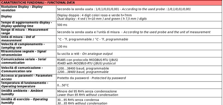
CARATTERISTICHE FUNZIONALI - FUNCTIONAL DATA Risoluzione Display - Display
resolution Secondo la sonda usata : 1/0,1/0,01/0,001 - According to the used probe : 1/0,1/0,01/0,001
Display Display doppio : 4 digit colori rosso e verde h=7mm
Dual display : 4 red ( h=10 mm ) and green ( h 7,5 mm ) digits Tempo di aggiornamento display -
Display updating time 500 ms
Range di misura - Measurement
range Secondo la sonda usata e l’unità di misura - According to the used probe and the unit of measurement
Unità di misura - Unit of
measurement °C - °F, programmabile / °C - °F, programmable
Velocità di campionamento -
Sampling rate 130 ms
Ritrasmissione segnale - Signal
retransmission Su uscita a relé - On analogue output
Comunicazione seriale - Serial
communication RS485 con protocollo MODBUS-RTU (JBUS)RS485 with MODBUS-RTU (JBUS) protocol Velocità di comunicazione -
Communication rate 1200…38400 baud, programmabile 1200…38400 baud, programmable Accesso ai parametri - Parameters
access Protetto da password - Protected by password
Temperatura di funzionamento -
Operating temperature 0…50°C
Umidità ambiente - Ambient
humidity Minore del 95 RH% senza condensazioneLower than 95 RH% without condensation
Umidità di esercizio - Operating
humidity 30…95 RH% senza condensa30…95 RH% without condensation
TABELLA SELEZIONE TERMOREGOLATORI - TEMPERATURE CONTROLLER SELECTION TABLE EL.CO MOD.: ELK94
DIMENSIONI
DIMENSIONS DESCRIZIONEDESCRIPTION CODICICODES CODES’ DESCRIPTIONDESCRIZIONE CODICI
DIN 48X96
ALIMENTAZIONE / POWER SUPPLY 24 24 V AC/DC
240 100-240 V AC/DC OUTPUT 1 R SPDT 6 A resistive relay S VDC for SSR I 0/4-20 mA V 0/2-10 V OUTPUT 2 - No uscita-None
2R SPST-NO 4 A resistive relay
2S VDC for SSR
2I 0/4-20 mA
2V 0/2-10 V
OUTPUT 3
- No uscita-None
3R SPST-NO 4 A resistive relay
3S VDC v SSR
OUTPUT 4
- No uscita-None
4R SPST-NO 4 A resistive relay
4S VDC for SSR
OUTPUT 5
- No uscita-None
5R SPST-NO 4 resistive relay
5S VDC v SSR
COMUNICAZIONE E INGR. PER TA COMMUNICATION AND CT INPUT
- No uscita-None
S RS 485 ModBus
HB Current transformer CT input TS RS 485 and CT input
Re
v.
06-20
11
ESEMPI COMPOSIZIONI CODICI - EXAMPLES OF CODES’ COMPOSITION
ESEMPI COMPOSIZIONI CODICI - EXAMPLES OF CODES’ COMPOSITION
TABELLA SELEZIONE TERMOREGOLATORI - TEMPERATURE CONTROLLER SELECTION TABLE EL.CO MOD.: ELK94S
DIMENSIONI
DIMENSIONS DESCRIZIONEDESCRIPTION CODICICODES CODES’ DESCRIPTIONDESCRIZIONE CODICI
DIN 48X96
ALIMENTAZIONE / POWER SUPPLY 24 24 V AC/DC
240 100-240 V AC/DC
OUTPUT 1 R SPDT 6 A resistive relay
S VDC for SSR
OUTPUT 2
- No uscita-None
2R SPST-NO 4 A resistive relay
2S VDC for SSR
OUTPUT 3
- No uscita-None
3R SPST-NO 4 A resistive relay
3S VDC for SSR
OUTPUT 4
- No uscita-None
4R SPST-NO 4 A resistive relay
4S VDC for SSR
OUTPUT 5
- No uscita-None
5R SPST-NO 4 resistive relay
5S VDC for SSR
INGRESSO PER TA / CURRENT TRANSFORMER INPUT HB Current transformer CT input
ELK94 24 2R 3R 4R 5R S
Mod. Termoregolatore / Temperature controller model Alimentazione / Power supply
OUT1 OUT2 OUT3 OUT4 R OUT5
Comunicazione e ingresso per TA / Communication and CT input
ELK94-24-R-2R-3R-4R-5R-S
ELK94-24-R-2R---S
ELK94S 24 2R 3R 4R 5R HB
Mod. Termoregolatore / Temperature controller model Alimentazione / Power supply
OUT1 OUT2 OUT3 OUT4 R OUT5
Ingresso per TA / Current transformer input
ELK94S-24-R-2R-3R-4R-5R-HB
ELK94S-24-R-2R-3R--HB
Rev. 06 -2 01 1
COLLEGAMENTI - CONNECTIONS
ACCESSORI - ACCESSORIES ACCESSORI pag. 31 ACCESSORIES pag. 31Re
v.
06-20
11
TERMOREGOLATORI E VISUALIZZATORI ELETTRONICI DIGITALI 33X75
33X75 DIGITAL TEMPERATURE CONTROLLERS AND DIGITAL ELECTRONIC PANEL
METERS
REGOLATORI A MICROPROCESSORE SERIE ELK 3 pag. 18
ELK 3 MICROPROCESSOR BASED REGULATORS SERIES pag. 18
REGOLATORI DI TEMPERATURA PER REFRIGERAZIONE SERIE ELZ pag. 23
ELZ TEMPERATURE CONTROLLERS SERIES FOR REFRIGERATION pag. 23
REGOLATORI DI TEMPERATURA PER REFRIGERAZIONE SERIE ELY pag. 25
ELY TEMPERATURE CONTROLLERS SERIES FOR REFRIGERATION pag. 25
VISUALIZZATORI DIGITALI SERIE ELV- EDL pag. 27
ELV- EDL DIGITAL PANEL METERS SERIES pag. 27
ACCESSORI pag. 31
ACCESSORIES pag. 31
SONDE DI TEMPERATURA pag. 40
TEMPERATURE PROBES pag. 40
REGOLATORI A MICROPROCESSORE SERIE ELR38 E ELR38T pag. 21
ELR38 AND ELR38T MICROPROCESSOR BASED REGULATORS SERIES pag. 21
VISUALIZZATORI DIGITALI SERIE ELV- EDL pag. 27
Rev.
06
-2
01
1
REGOLATORI A MICROPROCESSORE SERIE ELK 3
ELK 3 MICROPROCESSOR BASED REGULATORS SERIES
ELK 38
ELK 38 S
ELK 39
ELK 31
ELK 32
DATI TECNICI -
TECHNICAL DATA
CARATTERISTICHE ELETTRICHE - ELECTRICAL DATA
Alimentazione
Power supply 12, 24 VAC/DC, 100..240 VAC +/-10% 12 VAC/VDC
Assorbimento
Power consumption 4 VA circa - 4 VA approx.
Frequenza AC
AC Frequency 50 / 60 Hz
CARATTERISTICHE INGRESSI - INPUT DATA
4 differenti configurazioni di multi-ingresso
4 different configuration for programmable multi-input
Termocoppie J, K, S - secondo IEC 584-2 Classe di precisione 1 o 2, Pt 100 - secondo IEC 751 Classe di precisione A o B, Termocoppie Infrarosso Elco IRS J e K, 0…50 mV, 0…60 mV, 12…60 mV
Thermocoupes J, K, S - According to IEC 584-2 Accuracy class 1 or 2, Pt 100 - According to IEC 751. Accuracy class A or B,
ELCO Infrared Thermocouples IRS J and K, 0…50 mV, 0…60 mV, 12…60 mV Termocoppie J, K, S - secondo IEC 584-2 Classe di precisione 1 o 2, Termistore PTC KTY 81-121 (990 Ω a 25°C) Termistore NTC 103AT-2 (10 kΩ a 25°C),
Termocoppie Infrarosso Elco IRS J e K, 0…50 mV, 0…60 mV, 12…60 mV Thermocouples J, K, S - According to IEC 584-2 Accuracy class 1 or 2,
PTC KTY 81-121 (990 Ω at 25°C)NTC 103AT-2 (10 kΩ at 25°C), ELCO Infrared Thermocouples IRS J and K, 0…50 mV, 0…60 mV, 12…60 mV
0/4...20 mA 0/1…5 V, 0/2…10 V Ingressi Digitali
Digital input -- 2 programmable digital inputs2 ingressi programmabili Impedenza per ingressi
analogici
Normalized signals input impedance
Per ingresso 0/4…20 mA : 51 Ω - per ingresso mV e V : 1 MΩ for 0/4…20 mA input : 51 Ω - for mV and V input : 1 MΩ
CARATTERISTICHE USCITE - OUTPUT DATA
Relè - Relay
2 uscite SPDT (8 A-AC1, 3 A-AC3 / 250 VAC)
Up to 2 outputs SPDT(8 A-AC1, 3 A-AC3 / 250 VAC) 2 uscite SPST-NO + 2 uscite SPDT(8 A-AC1, 3 A-AC3 / 250 VAC) 2 outputs SPST-NO + 2 outputs SPDT
(8 A-AC1, 3 A-AC3 / 250 VAC) Vita elettrica relè
Relay electric life 100000 operazioni - 100000 operations
Tensione per pilotaggio SSR
Voltage for SSR driving
Fino a 2 uscite: 8 mA / 8 VDC Con protezione contro cortocircuiti
Up to 2 outputs : 8 mA / 8 VDC with short circuits protection
Fino a 4 uscite: 10 mA / 10 VDC Con protezione contro cortocircuiti
Up to 4 outputs : 10 mA / 10 VDC with short circuits protection Uscita alimentazione ausiliaria
Auxiliary power supply output 12 VDC / 20 mA max, only for instruments with 12 VAC/DC as power supply12 VDC / 20 mA max, solo per strumenti con alimentazione a 12 VAC/DC
CARATTERISTICHE FUNZIONALI - FUNCTIONAL DATA
Controllo - Control ON/OFF, Zona Neutra, PID a singola e doppia azione, programmabili
ON/OFF, Neutral Zone, programmable PID single and double action
Multi Set Point Fino a 4 Set Points programmabili
Up to 4 programmable Set Points Precisione
Overall accuracy +/-0,5% fondo scala+/-0.5% full scale +/-0,15% fondo scala+/-0.15% full scale Risoluzione Display
Display resolution According to the used probe 1/0,1/0,01/0,001Secondo la sonda usata : 1/0,1/0,01/0,001 Range di misura
Measurement range According to the used probe and to the measurement unitSecondo la sonda usata e l'unità di misura Compensazione Giunto freddo
Max. cold junction compensation drift
0,04°C/°C con temperatura di esercizio 0…50°C dopo un tempo di pre-riscaldo di 20 min. 0.04°C/°C with operating temperature 0…50°C after warm-up time of 20 min. Velocità di campionamento
Sampling rate 8 campioni al secondo - 8 samples per second
* °C-RH%-bar * PID * RS485 * 4 RELÉ * 4 RELAYS * 37x75 mm
Re v. 06-20 11
DIMENSIONI (mm) - DIMENSIONS (mm)
SCHEMI DI COLLEGAMENTO - WIRING DIAGRAMS
DATI TECNICI -
TECHNICAL DATA
Comunicazione seriale
Serial communication - RS485 con protocollo MODBUS-RTU (JBUS) RS485 with MODBUS-RTU (JBUS) protocol
Velocità di trasmissione
Serial transmission rate - 1200…38400 baud, programmabile1200…38400 baud, selectable
Display 4 digit rossi h=12 mm
4 red digit h=12 mm 4+4 digit rossi/verdi h=7 mm4+4 red/green digith=7 mm 4 digit rossi h=12 mm4 red digit h=12 mm 4+4 red/green digith=7 mm4+4 digit rossi/verdih=7 mm Accesso ai Parametri
Parameters access Protetto da password - Protected by password
Programmazione
Fast parameters programming Tramite tastiera frontale o con chiave di programmazione "KEY01" By keyboard or by using fast programming tool "KEY01" Temperatura ambiente di
esercizio
Operating temperature 0…50°C
Umidità ambiente di esercizio
Operating humidity 30…95 RH% senza condensa - 30…95 RH% without condensation
CARATTERISTICHE MECCANICHE - MECHANICAL CHARACTERISTICS
Contenitore
Housing Plastica autoestinguente, UL 94 V0Self-extinguishing plastic, UL 94 V0
Dimensioni
Dimensions 33x75 mm - profondità 64 mm - 33x75 mm - depth 64 mm
Peso
Weight 180 g circa - 180 g approx. 150 g. circa - 150 g. approx.
Connessioni
Connections Morsettiera a vite 2,5 mm2 - 2,5 mm2 screw terminal block
Montaggio
Mounting A pannello in foro 29x71 mm - Flush in panel in 29x71 mm hole
Protezione frontale
Front panel protection IP 65 montaggio a pannello con guarnizione - IP 65 mounted in panel with gasket
ELK 38
ELK 38 S
ELK 39
ELK 31
ELK 32
SV SV PV PV Ou t O ut SET SET 2 1 ELK 39 ELK 39
ELK 31
ELK 32
ELK39 ELK38 S ELK38Rev.
06
-2
01
1
ESEMPI COMPOSIZIONI CODICI - EXAMPLES OF CODES’ COMPOSITION
ESEMPI COMPOSIZIONI CODICI - EXAMPLES OF CODES’ COMPOSITION
ACCESSORI - ACCESSORIES ACCESSORI pag. 31
ACCESSORIES pag. 31
CODIFICA - CODING
ELK 31
Singolo Display Single Display33 x 75
ELK 32
Doppio DisplayDouble DisplayDescrizione
Description C o d i c iC o d e s Codes’ DescriptionDescrizione Codici
Segnale in ingresso Input Signal V 0-1/5V, 0-2/10 V I 0-4/20 mA E TC (J,K,S,IR) + PTC, NTC, mV C TC (J,K,S,IR) + PT100, mV Uscita principale OUT 1
Main output OUT 1
R Relè - Relay
S 10 mA / 10 VDC per SSR10 mA / 10 VDC for SSR Seconda uscita OUT 2
Second output OUT 2
2R Relè - Relay 2S 10 mA / 10 VDC per SSR10 mA / 10 VDC for SSR
- No uscita-None Terza UscitaOUT 3
Third output OUT 3
3R Relè - Relay 3S 10 mA / 10 VDC per SSR10 mA / 10 VDC for SSR
- No uscita-None Quarta UscitaOUT 4
Fourth output OUT 4
4R Relè - Relay 4S 10 mA / 10 VDC per SSR10 mA / 10 VDC for SSR
- No uscita-None Comunicazione Seriale
Serial Communication S- No - RS485None
Ingresso Digitale
Digital Input IA
Ingresso digitale Digital Input
- No - None
ELK 38 / ELK 38 S
Singolo Display Single Display33 x 75
ELK 39
Doppio DisplayDouble DisplayDescrizione
Description C o d i c iC o d e s Codes’ DescriptionDescrizione Codici
Alimentazione Power supply 12 12 VAC/DC 24 24 VAC/DC 240 100..240 VAC Segnali in ingresso Input Signal V 0-1/5V, 0-2/10 V I 0/4-20 mA E TC (J,K,S,IR) + PTC,NTC, mV C TC (J,K,S,IR) + PT100, mV Uscita principaleOUT 1
Main output OUT 1
R Relè / Relay
S 8 mA / 8 VDC per SSR8 mA / 8 VDC for SSR Seconda uscita OUT 2
Second output OUT 2
2R Relè / Relay 2S 8 mA / 8 VDC per SSR8 mA / 8 VDC for SSR
- No uscita-None
ELK 38 - 24 - C - R - 2R
Mod. Termoregolatore / Temperature controller model Alimentazione / Power supply
Uscita 1 / Output 1 Uscita 2 / Output 2
ELK 39 - 24 - C - R - 2R
Segnale Ingresso / Imput Sgnal
ELK 38 S - 24 - C - R - 2R
ELK 32 - C - R - 2R - 3R - 4R - S - IA
Mod. Termoregolatore / Temperature controller model Segnale Ingresso / Input Signal
Uscita 1 / Output 1 Uscita 2 / Output 2 Uscita 3 / Output 3 Uscita 4 / Output 4
Interfaccia di Comunicazione / Comunication Interface
ELK 31 - C - R - 2R - 3R - 4R - S - IA
Re
v.
06-20
11
REGOLATORI A MICROPROCESSORE SERIE ELR38 E ELR38T
ELR38 AND ELR38T MICROPROCESSOR BASED REGULATORS SERIES
DATI TECNICI -
TECHNICAL DATA
ELR 38
ELR 38T
CARATTERISTICHE ELETTRICHE - ELECTRICAL DATA
Alimentazione
Power supply 100..230 VAC +/-10%
Assorbimento
Power consumption 6 VA circa -6 VA approx.
Frequenza AC
AC Frequency 50 / 60 Hz
CARATTERISTICHE INGRESSI - INPUT DATA
Ingresso per temocoppie
Thermocouple input
Tipo: J,K programmabile - Type: J,K programmable
Risoluzione: 0,1°C con cambio scala automatico - Resolution: 0,1°C with automatic scale change Unità ingegneristiche: °C o °F progrqammabile - Unit of measurement: °C or °F programmable
Giunto freddo: compensazione automatica da 0 a +50°C -
Cold junction: automatic compensation from 0 to +50°C
Deriva del giunto di riferimento: 0,1°C/°C @ 25°C dopo un tempo di warm-up (accensione strumento) di 20 min
Cold junctions accuracy: 0,1°C/°C @ 25° after a warm-up (instrument switch-on) of 20 min Calibrazione: secondo EN 60584-1 /Calibration: according to EN 60584-1
Segnalazione rottura sensore: a fondo scala / Burn-out: at end of scale Ingresso per termoresistenze (RTD)
Thermoresistance input (RTD)
Tipo: Pt 100 2 fili - Type: Pt 100 2 wires
Risoluzione: 0,1 ° con scambio scala automatico - Resolution: 0,1°C with automatic scale change Unità ingegneristiche: °C o °F programmabile - Unit of measurement: °C or °F programmable
Segnalazione rottura sensore: a fondo scala - Burn-out: at end of scale Segnalazione: secondo EN 60751/A2 - Calibration: according to EN 60751-A2 Ingresso per termistori
Thermistor input
Tipo: KTY 81-121 (990 Ω @ °C) e NTC 103AT-2 (10 Ω @ 25 °C) -
Type: KTY 81-121 (990 Ohm @ °C) and NTC 103AT-2 (10 Ohm @ 25 °C)
Unità ingegneristiche: °C o F programmabile - Unit of measurement: °C or °F programmable
CARATTERISTICHE USCITE - OUTPUT DATA
Relè - Relay 2 uscite SPDT (8 A-AC1, 3 A-AC3 / 250 VAC)
Up to 2 outputs SPDT (8 A-AC1, 3 A-AC3 / 250 VAC) Vita elettrica relè
Relay electric life 100000 operazioni - 100000 operations
Tensione per pilotaggio SSR
Voltage for SSR driving Fino a 2 uscite: 20 mA / 10 VDC Up to 2 outputs : 20 mA / 10 VDC
CARATTERISTICHE FUNZIONALI - FUNCTIONAL DATA
Controllo - Control Zona Neutra, ON/OFF singola azione, PID a singola azione, SP1 comanda Out1- SP2 comanda Out2 Neutral Zone, ON/OFF single action, PID single action, SP1 drives Out1- SP2 dirves Out2 Precisione
Overall accuracy +/-0,5% span + 1 digit @ 25°C
Risoluzione Display
Display resolution According to the used probeSecondo la sonda usata Range di misura
Measurement range According to the used probe and to the measurement unitSecondo la sonda usata e l'unità di misura Velocità di campionamento
Sampling rate 1 secondo - 1 second
Display display singolo 3 digit rossi + segno h=12 mm
3 red digit single display h=12 mm Programmazione
Fast parameters programming Tramite tastiera frontale o con chiave di programmazione "KEY01" By keyboard or by using fast programming tool "KEY01"
* Solo 24 parametri (configurazione e run-time) * Only 24 parameters (configuaration and run-time) * Ingresso per TC, J, K, RTD, PTC, NTC
* Input for TC, J or K, RTD, PTC, NTC
* Risoluzione 0,1 °C con cambio scala automatico (auto-ranging) * Resolution 0,1°C with automatic scale change (auto-ranging) * Fino a 2 uscite a relè in scambio
* Up to 2 SPDT relau outputs
* Controllo/ Control: -PID singola azione con Autotuning - PID single action with Autotuning -ON/OFF singola azione -ON/OFF single action
-ON/OFF doppia azione (H/C) (a zona neutra) -ON/OFF SP1 comanda Out 1-SP2 comanda Out 2 -ON/OFF SP1 drivers Out 1-SP2 drivers Out 2
* Protezione parametri con password programmabile oppure "Blocco tastiera" * Parameters protection with programmable password or "Keyboard Lock" * Funzione Soft start o Ritardo all’accensione (od)
* Soft start or Start up delay (od) function * Tempo protezione compressore * Compressor protection time * Accesso diretto al set point * Tastiera "Sensitive Touch" * "Sensitive Touch" keyboard.
ELR38
ELR38T
Tastiera "Sensitive Touch"Rev. 06 -2 01 1
CODIFICA - CODING
ESEMPI COMPOSIZIONI CODICI - EXAMPLES OF CODES’ COMPOSITION
CARATTERISTICHE FUNZIONALI - FUNCTIONAL DATA
Temperatura ambiente di esercizio
Operating temperature 0…50°C
Umidità ambiente di esercizio
Operating humidity 30…95 RH% senza condensa - 30…95 RH% without condensation
CARATTERISTICHE MECCANICHE - MECHANICAL CHARACTERISTICS
Contenitore
Housing Plastica autoestinguente, UL 94 V0Self-extinguishing plastic, UL 94 V0 Dimensioni
Dimensions 33x75 mm - profondità 64 mm - 33x75 mm - depth 64 mm
Peso
Weight 180 g circa - 180 g approx.
Connessioni
Connections Morsettiera a vite 2,5 mm2 - 2,5 mm2 screw terminal block
Montaggio
Mounting A pannello in foro 29x71 mm - Flush in panel in 29x71 mm hole
Protezione frontale
Front panel protection IP 65 montaggio a pannello con guarnizione - IP 65 mounted in panel with gasket
ELR38 / ELR38T
Singolo DisplaySingle Display 33 x 75Descrizione
Description C o d i c iC o d e s Codes’ DescriptionDescrizione Codici
Alimentazione Power supply 12 not isolated12 V DC 24 24 V AC/DC 240 100...240 V AC/DC Segnali in ingresso Input Signal T TC(J,K) P PT100 PT PTC/NTC Uscita principaleOUT 1
Main output OUT 1
R Relè / Relay
S VDC per SSRVDC for SSR Seconda uscita OUT 2
Second output OUT 2
2R Relè / Relay
2S VDC per SSR VDC for SSR
- No uscita-None
DIMENSIONI (mm) - DIMENSIONS (mm)
SCHEMA DI COLLEGAMENTO - WIRING DIAGRAM
ELR 38 - 240 - T - R - 2R
Mod. Termoregolatore / Temperature controller model Alimentazione / Power supply
Uscita 1 / Output 1 Uscita 2 / Output 2 Segnale Ingresso / Imput Sgnal
Re
v.
06-20
11
REGOLATORI DI TEMPERATURA PER REFRIGERAZIONE SERIE ELZ
ELZ TEMPERATURE CONTROLLERS SERIES FOR REFRIGERATION
ELZ 10
ELZ 11
DATI TECNICI -
TECHNICAL DATA
CARATTERISTICHE ELETTRICHE - ELECTRICAL DATA
Alimentazione
Power supply 12, 24 VAC/DC, 100..240 VAC +/-10%
Assorbimento
Power consumption 3 VA circa - 3 VA approx.
Frequenza AC
AC Frequency 50 / 60 Hz
CARATTERISTICHE INGRESSI - INPUT DATA
Termistori
Thermistors Ingresso programmabile per PTC KTY 81-121 (990 Programmable input for PTC KTY 81-121 (990 Ω at 25°C) or NTC 103AT-2 (10 Ω a 25°C) o NTC 103AT-2 (10 ΩW at 25°C)ΩW a 25°C)
Ingresso Digitale
Digital input / 1 per contatto libero da tensione1 for free voltage contact
CARATTERISTICHE USCITE - OUTPUT DATA
Relè - Relay
1 uscita SPST-NO o1 uscita SPDT 16A-AC1,6A-AC3/250 VAC 1 relay SPST-NO or 1 relay SPDT
16A-AC1,6A-AC3/250 VAC
1 uscita SPST-NO 16A-AC1, 6A-AC3/250 VAC o 1 uscita SPDT 16A-AC1, 6A-AC3/250 VAC + 1 uscita SPDT 5A-AC1, 3A-AC3/250 VAC
1 relay SPST-NO 16A-AC1, 6A-AC3/250 VAC or 1 relay SPDT 16A-AC1,6A-AC3/250 VAC+1 relay SPDT 5A-AC1,3A-AC3/250 VAC Vita elettrica relè
Relay electric life 100000 operations for relay SPST-NO type - 50000 operations for relay SPDT type100000 operazioni per relè SPST-NO - 50000 operazioni per relè SPDT
CARATTERISTICHE FUNZIONALI - FUNCTIONAL DATA
Controllo - Control ON/OFF
Precisione
Overall accuracy +/-0,5% fondo scala
Risoluzione Display
Display resolution 1° o 0,1° - 1° or 0,1°
Range di misura
Measurement range PTC -50…+150°C NTC -60…+109°C
Unità di misura
Measurement Unit °C - °F, programmabile - °C - °F, programmable
Tempo di campionamento
Sampling rate 130 msec
Display 4 digit rossi h=12 mm - 4 red digit h=12 mm
Controllo sbrinamento
Defrost control /
Allarme acustico
Acoustic alarm / Buzzer interno - Internal Buzzer
Programmazione
Fast parameters programming Tramite tastiera frontale o con chiave di programmazione "KEY01"By keyboard or by using fast programming tool "KEY01" Accesso ai Parametri
Parameters access Protetto da password - Protected by password
Temperatura ambiente di esercizio
Operating temperature 0…50°C
Umidità ambiente di esercizio
Operating humidity 30…95 RH% senza condensa - 30…95 RH% without condensation
CARATTERISTICHE MECCANICHE - MECHANICAL CHARACTERISTICS
Contenitore
Housing Plastica autoestinguente, UL 94 V0 - Self-extinguishing plastic, UL 94 V0
Dimensioni
Dimensions 33x75 mm - profondità 64 mm - 33x75 mm - depth 64 mm
Peso
Weight 115 g. circa - 115 g. approx.
Connessioni
Connections Morsettiera a vite 2,5 mm2 - 2,5 mm2 screw terminal block
Montaggio
Mounting A pannello in foro 29x71 mm - Flush in panel in 29x71 mm hole
Protezione frontale
Front panel protection IP 65 montaggio a pannello con guarnizione - IP 65 mounted in panel with gasket
* 33x75 mm * 100/240 VAC * Relè 16 A * Relay 16 A