Transport Network Function Virtualization
Ricard Vilalta,
Member, IEEE
, Raul Mu˜noz,
Senior Member, IEEE
, Arturo Mayoral, Ramon Casellas,
Senior
Member, IEEE
, Ricardo Mart´ınez,
Senior Member, IEEE
, Victor L´opez, and Diego L´opez
(Invited Paper)
Abstract— In this paper, we present a Network Function
Virtualization (NFV) architecture to deploy different Virtualized Network Functions (VNF) on an optical Transport Network. NFV concepts do not only apply to data plane functions (i.e., packet processing or forwarding), but also to control plane functions, such as path computation. Firstly, we focus on the IT and Network Resources that are virtualized to provide the required VNFs. Secondly, we provide an example of VNF on top of the Virtualized Infrastructure, by proposing a Path Computation Element (PCE) architecture to deploy a PCE by means of NFV. The instances of the virtualized PCE are deployed on demand, but they are perceived as a single network element. We present the benefits of such approach by providing experimental validation.
Index Terms— Network Function Virtualization, NFV
Orches-tration and Management, Cloud and Network OrchesOrches-tration, Path Computation Element, GMPLS, OpenDaylight, OpenStack.
I. INTRODUCTION
N
ETWORK Functions Virtualization (NFV) aims at usingIT virtualization techniques to virtualize entire classes of network node functions. A Virtualized Network Function (VNF) consists of a network function running as software on a single or several hosts, typically inside virtual machines, instead of having custom hardware appliances for the proposed network function [1]. Possible examples of VNFs include load balancers, firewalls, security or Authentication, Authorization and Accounting (AAA) network functions. Network Functions Virtualization is applicable to any data plane packet process-ing and control plane function in fixed and mobile network infrastructures [1].
VNF are deployed on top of IT and Network resources which can be located in different geographically distributed NFV Infrastructure Points of Presence (NFVI-PoP), which might be interconnected using transport networks. There is the need of offering this IT and Network resources as a whole, by means of Virtualized Infrastructure Managesr, enabling it with the flexibility provided with the Software Defined Networking (SDN) architecture.
SDN has emerged as the most promising candidate to im-prove network programmability and dynamic adjustment of the
This paper was supported by the EU-Japan coordinated project STRAUSS (grant agreement no 608528, and the Spanish Ministry of Economy and Competitiveness (MINECO) through the project FARO (TEC2012-38119).
R. Vilalta, R. Mu˜noz, A. Mayoral, R. Casellas, and R. Mart´ınez are with the Centre Tecnol`ogic de Telecomunicacions de Catalunya (CTTC), Av. Carl Friedrich Gauss 7, 08860 Castelldefels (Barcelona), Spain, e-mail: {ricard.vilalta, raul.munoz, arturo.mayoral, ramon.casellas, ricardo.martinez}@cttc.es
V. L´opez and D. L´opez are with Telefonica I+D, e-mail:
{victor.lopezalvarez, diego.r.lopez}@telefonica.com
network resources. SDN proposes a centralized architecture where the control entity (SDN controller) is responsible for providing an abstraction of network resources through pro-grammable APIs. One of the main benefits of this architecture resides on the ability to perform control and management tasks of different network forwarding technologies such as packet/flow switches, circuit switching and optical wavelength switched transport technologies, by the same network con-troller [2] altogether with upper-layer applications.
OpenFlow protocol allows to program forwarding rules into OpenFlow virtualized switches inside DCs, through the defi-nition of flows which can filter traffic of different traditional networking protocols. Inter-DCs aggregated traffic can be transported by a Generalized Multiprotocol Label (GMPLS)-controlled optical transport network (e.g., WSON or Flexi-grid DWDM transport network). A centralized entity, defined as SDN controller, integrates control functions of both network domains.
A transport Path Computation Element (PCE) is a transport network function, which is able to perform constrained path computation on a graph representing a network (Traffic En-gineering Database - TED) [3]. The PCE global architecture and communication protocol (PCEP) have been standardized by IETF. The PCE can be run as an application on top of Commercial Off-The-Shelf (COTS) equipment [4]. The initial driver for the deployment of PCEs was the increasing complexity of path computation. An Active Stateful Path Computation Element (AS-PCE) [5] is a PCE which maintains not only the traffic engineering information (link and node states), but also the state of the active connections in the network. The AS-PCE can receive the right of managing the active paths controlled by the nodes, allowing the PCE to modify or tear-down the connections established in the data plane. Here we propose to introduce an external AS-PCE as an SDN-enabler for a GMPLS-controlled optical transport network.
The operations done in the PCE may be computationally intensive when running the path computation for transport connection provisioning or re-optimization on large production networks. To overcome this scalability limitation, several solu-tions have been proposed, being hierarchical PCE, and front-end/back-end PCE [3]. In this paper, we propose to extend the concept of NFV to transport networks by removing a dedicated PCE server and move the PCE functionality to the Cloud. The key benefit of this proposal will be the flexibility of providing dedicated IT resources to path computation.
To this end, first we propose a SDN IT and Network Orches-trator (SINO), which corresponds to Virtualized Infrastructure Managers in the ETSI NFV architecture. The SINO
pro-vides an integrated orchestration of IT and network resources to provide intra/inter-DC network connectivity for deployed virtual machines (VMs) using OpenStack Cloud Computing system. The Intra/Inter-DC network connectivity is controlled by an extended OpenDaylight (ODL) SDN Controller, with extensions to request LSP provisioning to an external AS-PCE. The integrated orchestration of IT and network resources has been previously demonstrated at [6] and [7].
To demonstrate the feasibility of deploying VNF on top of the proposed SINO, we propose the adoption of the NFV architecture to deploy a PCE dedicated to path computation of a transport network as a VNF. Although the NFV architecture has successfully been demonstrated for mobile networks, there have been only few attempts to introduce this architecture to core networks. A PCE NFV orchestrator is introduced, so that the proposed transport PCE NFV is be able to handle intense peak loads of path computation requests. The NFV orchestrator dynamically deploys virtual PCEs (vPCEs) on demand to keep the quality of the VNF (e.g., in terms of latency, request processing time, dedicated algorithms, etc.). A vPCE is a PCE instance, which is run as a software application on a cloud computing environment (e.g., a virtual machine). We also introduce a PCE DNS [8] in order to offer the deployed vPCEs as a single VNF perceived by the different Path Computation Clients (PCC).
This paper extends [9] with an experimental validation of the extended transport SDN/NFV architecture, by providing details on the deployed NFV Infrastructure and the SINO, and also providing the obtained results of deploying a transport PCE as a VNF.
This paper is organized as follows: Section II details the overall transport network function virtualization architecture, while Section III and Section IV focus on the SINO and PCE as a VNF, respectively. Section V provides experimental performance of the proposed architecture. Finally, Section VI concludes the paper.
II. TRANSPORTNETWORKFUNCTIONVIRTUALIZATION
Virtual IT resources VNF lifecycle VNF #n Manager VNF Controller Packet domain VNF 1 VNF 2 VNF N OVS … Datacenter 1 Datacenter 2 Packet domain Optical domain
SDN IT and Network Orchestrator (SINO)
VNF 1 Manager VM M OVS VM 2 VM 1 … … OpenStack REST API OpenFlow PCEP Distributed Cloud Controller Network Orchestrator NFV Orchestrator
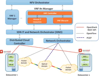
Fig. 1: Transport Network Function Virtualization architecture
The architecture for providing Transport NFV is depicted in Figure 1. The main components of this proposed architecture are: NFV Orchestrator, VNF Manager, SDN IT and Network Orchestrator (SINO), Distributed Cloud Controller, and Net-work Orchestrator.
The considered NFV Management and Orchestration is defined by the ETSI as the responsible to cover the life cycle management of the physical and software resources to support the infrastructure virtualization and the life cycle of the different VNF [10].
The NFV Orchestrator is the final responsible of offering the previously proposed services. The importance of defining a NorthBound Interface (NBI) for the NFV Orchestrator is clear, as users or application shall need to use the NBI to request the NFV services. The NFV Orchestrator is responsible for handling the various VNF managers. A VNF manager is responsible for the life cycle management (i.e., creation, configuration, and removal) of a Virtual Network Function. Multiple VNF Managers may be deployed; a VNF Manager may be deployed for each VNF, or a VNF Manager may serve multiple VNFs [10].
The SDN IT and Network Orchestrator (SINO) is the responsible of the control and management of the interaction of a VNF with the different IT and network resources under its authority, as well as the virtualization of these resources. The SINO corresponds to Virtualised Infrastructure Manager in the ETSI NFV architecture. Some of the responsibilities of the SINO are: inventory of software, computing, storage and net-work resources, allocation of virtualization enablers on top of the mentioned IT and network resources, and management of the infrastructure resource allocation (e.g., increase resources to VMs, network virtualization, reduce energy consumption). Virtualization of IT resources might be provided by means of a Distributed Cloud Controller, which provides Infras-tructure as a Service. The infrasInfras-tructure consists of storage services, computing services, and IT networking services.
A Network Orchestrator (NO) is introduced in order to provision end-to-end connectivity within a multi-domain vir-tual network. The NO is responsible of orchestration of the different underlying networks, each controlled by a Physical SDN Controller (PSC). The NO must take into account the het-erogeneous underlying network resources (e.g., multi-domain, multi-layer and multi-control technologies). The Northbound Interfaces (NBI) of a PSC are typically technology and vendor dependent, so the NO shall implement different PSC plugins for each of the NBI. It is assumed that the PSCs are able to provide network topology information and flow programming functions.
In Section III, we present a detailed architecture for Cloud and Network Orchestrator, Distributed Cloud Controller and Network Orchestration, in order to provide distributed NFVI-PoP.
III. CLOUD ANDNETWORKORCHESTRATOR FOR
DISTRIBUTEDNETWORKFUNCTIONVIRTUALIZATION
INFRASTRUCTUREPOINTS OFPRESENCE
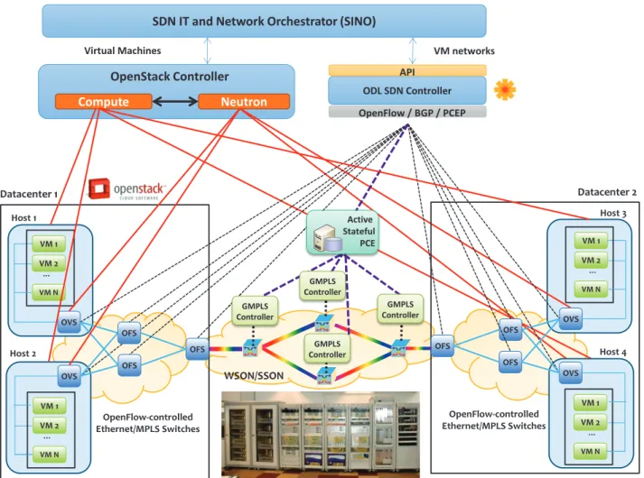
Figure 2 shows the considered system architecture. On top, the SINO is responsible for handling Virtual Machine
ODL SDN Controller API OpenFlow / BGP / PCEP Compute Neutron OpenStack Controller
SDN IT and Network Orchestrator (SINO)
Virtual Machines VM networks
WSON/SSON VM 1 VM 2 VM N Host 1 OVS … OpenFlow-controlled Ethernet/MPLS Switches VM 1 VM 2 VM N Host 2 OVS … Datacenter 1 OFS OFS OFS VM 1 VM 2 VM N Host 3 OVS … OpenFlow-controlled Ethernet/MPLS Switches VM 1 VM 2 VM N Host 4 OVS … Datacenter 2 OFS OFS OFS Active Stateful PCE GMPLS Controller GMPLS Controller GMPLS Controller GMPLS Controller
Fig. 2: Cloud and Network Orchestrator Architecture
(VM) and network connectivity requests, which are processed through the Distributed Cloud Controller, which is depicted as OpenStack Controller, and the Network Orchestrator, which is depicted as an extended OpenDayLight (ODL) SDN Con-troller. On top of the interconnected VM, the different VNF might be deployed.
The cloud and network orchestration process consists of two different steps: the VM creation and network connectivity provisioning (Fig. 3). The SINO requests the creation of a Virtual Machine (VM) instance to the OpenStack Controller, which, is responsible for the request to a specific computing host of the creation of the instance. The OpenStack Controller is also responsible to attach the VM to the virtual switch inside the host node, which is typically an OpenFlow software switch such as OpenVSwitch (OVS). When the VM creation is finished, the OpenStack Controller sends the VM’s networking details to the orchestrator (i.e., MAC address, IP address, and host computing node location).
The ODL SDN controller is a framework to implement end-to-end network control services in a centralized network entity (i.e., network orchestrator). The ODL SDN controller offers a complete set of programmable Application Programmable Interfaces (API) to northbound applications from where to re-quest networking information or switching configuration of the
network infrastructure. The interfaces exposed are completely agnostic to the underlying network infrastructure allowing applications to request network connectivity services without being bounded to specific networking protocols. The core of the ODL SDN Controller is a Service Abstraction Layer which translates internal controller services and external applications’ requests to the implemented networking protocols plugged in the southbound interface of the controller.
The southbound interface of ODL SDN Controller is com-posed by a set of plugins implementing different control and management protocols, to configure physical (hardware) network devices, such as OpenFlow, Netconf, Border Gateway Protocol (BGP) or PCEP among others.
We have extended ODL SDN controller with a module named PCEP-Speaker Service, which is responsible to request to an external AS-PCE the establishment of an optical LSP. The details for this extension are provided by [11].
The SINO workflow goes as detailed in Figure 3. The SINO requests to the ODL SDN controller to perform the flow establishment between the two VMs deployed by the VIRC. After computing the route, the ODL SDN controller is aware either of the positive reachability of the computing resources through the packet network (intra-DC) or whether an inter-DC connection is needed. In the first case, the ODL
SINO ODL
AS-PCE OVS 1 Client
VMs & Net
requests Start VMs
GET Network Topology VMs started JSON{Ok} VMs & Net created … OVS N PCInitiate{ERO} PCRpt{LspId} OF Flow_Mod OF Flow_Mod …
JSON {Nodes, Edges} PUT Establish LSP
PCReq{Src,Dst} PCRep{ERO}
JSON {OK, LspId} PUT Establish Flows
Fig. 3: Cloud and Network Orchestrator Workflow
SDN controller is ready to send the command to establish the forwarding rules to the OpenFlow-enabled switches and into the intra-DC switches. In the second case, the SDN controller needs to establish a lightpath between the DCs.
In order to establish a lightpath, between the DCs, we propose to use an AS-PCE, which has been demonstrated as a very robust and comprehensive solution to manage and control optical domains in a centralized manner [12]. With the presented active and stateful capabilities, the AS-PCE is a key SDN-enabler component.
AS-PCE can instantiate or tear down LSPs on the network through the PCEP stateful extensions using the LSP initiate request message (PCInitiate [13]). The PCInitiate message is the key-driver mechanism to request LSPs from outside the GMPLS control plane. The AS-PCE acts as an interface between the ODL SDN controller and the GMPLS control plane.
Once the lightpath has been established between the DCs, the SINO can proceed to send the command to establish the forwarding rules to the OpenFlow-enabled switches and into the intra-DC switches.
IV. TRANSPORTPCE VIRTUALNETWORKFUNCTION
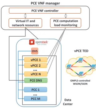
In this section, the proposed transport PCE NFV architecture is described (Fig. 4). A PCE NFV Orchestrator is the entity responsible for the deployment of the PCE as a VNF. The PCE NFV Orchestrator consists of three separated modules: PCE VNF provider, Virtual IT resources and PCE computation load monitoring.
The PCE VNF provider implements the necessary logic for deploying the necessary vPCE in order to guarantee the quality of the VNF. In order to guarantee the quality, the PCE VNF provider interacts with the PCE computation load monitoring module in order to obtain the necessary data to decide to deploy a new instance of a vPCE or to delete one, via the virtual IT resources module. Thus, the PCE VNF is the responsible for deploying the logic of the orchestrator.
The Virtual IT resources module is responsible for request-ing to the SINO the necessary IT and Network resources. The SINO allows the dynamic deployment and release of virtual machines with custom images running vPCE as an application
GMPLS-controlled WSON/SSON Virtual IT and network resources PCE computation load monitoring PCE VNF manager Data Center OVS
…
PCE VNF controller vPCE TED…
vPCE 1 vPCE 2 vPCE N PCE DNS PCC 1 PCC MFig. 4: PCE NFV Orchestrator Architecture
and the interconnection between them, although they might be geographically distributed. The cloud infrastructure must assign to the vPCE a new IP address from a set of available ones. This IP address is parsed and the PCE DNS is notified with the new IP address for a new available vPCE.
Finally, the PCE computation load monitoring module is the responsible for monitoring the quality of the VNF. The mon-itored parameters are a set of the PCE monitoring parameters defined in [14], which are exposed by the vPCEs, by means of an HTTP server. One of these parameters is the mean path processing time. If the mean path processing time exceeds a certain threshold, the PCE VNF could deploy a new vPCE to reduce the peak request load in the PCE VNF.
The need for path computations in a network is related to the intense dynamic usage of the network. It is also related to the need to perform in-operation network re-planning or network recovery. It is in these two scenarios, where we can expect the need for the deployment of vPCEs to perform the necessary path computations. When the situation that has generated the need for path computation ends, the PCE computation load monitoring module, shall detect its end and turn down the unnecessary vPCEs.
In the following subsections two different approaches for offering the running vPCE to be perceived as a single PCE by the different Path Computation Clients. The first approach consists on the usage of a PCE DNS to handle all the incomming requests and redirecting them to the allocated vPCE. The second approach is the usage of the front-end/back-end PCE architecture in order to use a front-front-end/back-end PCE as a proxy for all the deployed vPCEs, which act as back-end PCEs.
PCE VNF
Manager SINO PCE DNS
vPCE 1 vPCE N … PCC Computation Load High Computation Load
Start vPCE N Start vPCE N vPCE N started vPCE N started Add vPCE N PC Request PC Reply Whois PCE? vPCE N
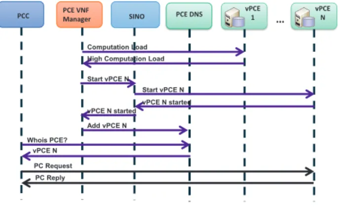
Fig. 5: PCE NFV Workflow
A. PCE VNF using PCE DNS
As a PCE discovery mechanism, a PCE DNS is proposed. DNS is a query-response based mechanism. A Path Compu-tation Client (a PCC) can use DNS to discover a PCE only when it needs to compute a path and does not require any other node in the network to be involved. In case of an intermittent PCEP session, which are systematically opened and closed for each PCEP request, a DNS-based query-response mechanism is suitable. Moreover, DNS supports load balancing where multiple vPCEs (with different IP addresses) are known in the DNS for a single PCE server name and are seen for the PCC as a single resource. Requests are load-balanced among vPCEs without any complexity at the PCC.
The messages exchanged between the different elements of the proposed architecture are displayed in Fig. 5. It can be observed, that the PCE NFV Orchestrator is the responsible for checking the different quality parameters to the deployed vPCEs. Once these quality parameters are received, the PCE VNF provider module within the PCE NFV Orchestrator is the responsible to determine whether a new vPCE is required. If a vPCE is selected to be deployed, the Virtual IT resources module will deploy a new virtual machine with the vPCE image, will assign a new IP address to the vPCE and once the vPCE is started, the Virtual IT resources module will notify the new vPCE IP address to the PCE DNS.
Once a PCC requires a new path computation, first will issue a DNS query to the PCE DNS. The PCE DNS is responsible to load balance the different vPCEs, so returns a single IP address corresponding to one of the vPCEs. Finally, the PCC establishes a path computation session with the corresponding vPCE.
B. PCE VNF using front-end/back-end PCE
The so-called front-end / back-end architecture is a new load balancing architecture based on the concept of a front-end and one or more dedicated back-ends, where the end client of PCC only sees the front-end, and operators may deploy different capabilities at back-ends. The common use case is when one or more PCEs are deployed in the same TE domain, so the back-end PCEs may use the same TED, although it is not mandatory [3]. The main motivations behind this work are
PCE VNF
Manager SINO Front-end PCE
vPCE 1 vPCE N … PCC Computation Load High Computation Load Start vPCE N Start vPCE N vPCE N started vPCE N started Add vPCE N PC Request PC Reply PC Request PC Reply
Fig. 6: PCE NFV Workflow using front-end/back-end PCE
related to scalability and load sharing policies while enabling some degree of specialization.
We propose to introduce a front-end PCE, which is notified by the PCE VNF Manager of the currently deployed vPCE. Figure 6 shows the detailed workflow for this architecture. It differs from the previously presented workflow for PCE DNS in the fact that a front-end PCE acts as a proxy for PC Requests, while in PCE DNS, the PCC issued a DNS request for the assigned vPCE. The front-end PCE processes the incomming PC Request and forwards it to the suitable vPCE, who responds it to the end PCE. Finally, the front-end PCE forwards the PC Reply to the PCC.
This architecture allows a higher degree of scalability and load sharing policies in comparison to PCE DNS. The pro-posed front-end/back-end architecture also provides a higher level of robustness and redundancy: even though the front-end PCE is still a single point of failure, its implementation is significantly simpler than a back-end-PCE (b-PCE) [3]. Moreover, redundancy techniques might be applied to recover from a front-end PCE failure.
V. EXPERIMENTALPERFORMANCE
In this section we provide an experimental validation of the proposed transport SDN/NFV architecture, by providing details on the deployed distributed NFVI-PoPs and its SINO, and also providing the obtained results of deploying a transport PCE as a VNF.
The proposed architecture has been validated in the Cloud Computing platform of the ADRENALINE Testbed. The OpenStack Havanna release has been deployed into five phys-ical servers with 2 x Intel Xeon E5-2420 and 32GB RAM each, one dedicated to the cloud controller and the other four as compute pool (hosts) for VM instantiation.
Four OpenFlow switches have been deployed using standard Custom Off The Shelf (COTS) hardware and run Open-VSwitch (OVS), which can be controlled by OpenFlow 1.0. Each Data Center border switch has been implemented using COTS hardware, a 10 Gb/s XFP tunable transponder and OVS. Finally, the GMPLS-controlled optical network is composed of an all-optical WSON with 2 ROADMs and 2 OXCs providing reconfigurable (in space and in frequency) end-to-end lightpaths, deploying a total of 610 km of G.652 and
G.655 optical fiber, with six DWDM wavelengths per optical link.
The SDN controller has been implemented with ODL service provider distribution, which has been expanded with several components such as a PCEP-Speaker module to estab-lish the PCEP session with the AS-PCE.
A. SDN IT and Network Orchestrator
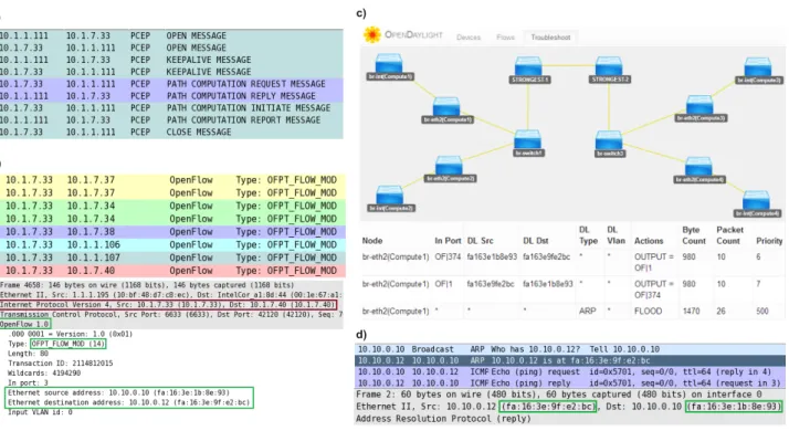
Figure 7.a shows the PCEP message exchange between ODL SDN controller and the external AS-PCE, which acts as a SDN enabler, to establish an LSP between the border nodes in the transport network. We can observe the PC Initiate Mes-sage issued from the ODL SDN controller, and the response message (PC Report) from the AS-PCE, when the LSP has been established.
Figure 7.b shows theOF P T F LOW M ODmessages sent
from the ODL controller to the corresponding OpenFlow switches. We can observe for example a Flow rule for VM with source MAC address (fa:16:3e:1b:8e:93) to VM destination MAC address (fa:16:3e:9f:e2:bc).
In Figure 7.c the abstracted topology from ODL is pre-sented, and also an example of the forwarding rules injected in one of the OVS. For example, we can observe a rule for ARP packets and a specific source MAC and destination MAC rule to filter the traffic associated to the VMs end points.
Finally, in Figure 7.d shows the ping exchange between the two previously presented VMs through the intra/inter DC network.
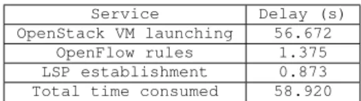
TABLE I: System Setup Delays
Service Delay (s)
OpenStack VM launching 56.672
OpenFlow rules 1.375
LSP establishment 0.873
Total time consumed 58.920
A measurement of the time spent to the IT and Network orchestration process is shown in Tab. I. We can observe that only 59 seconds have been necessary to fully deploy and interconnect two virtual machines located in different DCs.
B. Transport PCE VNF
The proposed NFV orchestrator has been developed in Python, and the PCE has been described in [3]. The PCE DNS server has been setup using bind9, which is the standard linux DNS server. All the deployed vPCE where sharing a static network view of a typical Spanish 14-node 44-link Flexi-grid DWDM network. In the future, BGP-LS could be used in order to dynamically synchronize the TED of the different vPCEs.
The deployed vPCEs allows the measurement of the rolling mean (we use a 10 request window) processing time of a request (time between a request is received and responded) via HTTP through an XML response.
Every new instance of vPCE is deployed by SINO API, which is responsible for IT and Network resources. All de-ployed virtual machines share a common file repository for
ease of synchronization. We have prepared a vPCE snapshot, which is able to easily run a vPCE.
The SINO API, responsible for network configuration, as-signs to the vPCE an IP address, which is later added as a possible resolution for pce.lab.cttc.es to the PCE DNS.
The PCC is responsible for issuing a DNS query, when a new path computation request is issued. When the PCE DNS receives a DNS query, it applies a simple load balancing algorithm by returning a different vPCE IP address for each query. Finally, the PCC establishes a PCEP session to the assigned vPCE. Figure 8 shows the standard PCEP session including OPEN, KEEPALIVE, PCRequest, PCReply and CLOSE messages.
In order to stress the proposed architecture, a PCC requests 500 requests per second. Each path computation request is randomly selected between two endpoints of the described flexi-grid network. The mean request processing time (Tproc) is measured as a mean of the previously defined request processing time of the current vPCEs. We do not expect this large number of requests in a dynamic provisioning scenario, but consider the necessity to provide a large number of path computations in an in-operation network re-planning or in failure recovery scenarios.
We have requested 10000 Path Computation Requests for each measurement. When a single vPCE (acting as a PCE) was deployed the Tproc was 279 microseconds. It can be observed that when more vPCEs have been deployed the measured Tproc is reduced. For example, for 6 vPCEs deployed, Tproc is 248 us (Fig. 9).
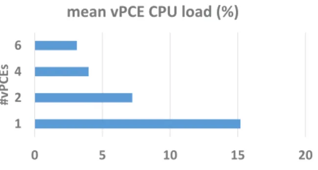
Figure 10 shows the mean measured CPU load at a single vPCE, when different vPCE have been deployed. The mea-sured CPU load tends to be balanced by the different vPCEs, when 2 vPCE are deployed the mean CPU load is of 7.2 %. If there are 6 vPCEs deployed the CPU load is of 3.1%. It can be observed, that if more vPCEs are deployed, the computational load is balanced between them, allowing a faster mean request processing time.
VI. CONCLUSIONS
We have presented a transport NFV architecture and we have provided a practical example of deploying transport PCE as a NFV. An orchestration mechanism for geographically distributed DC has been presented in order to provide the required SINO to deploy VNFs. We have also demonstrated extensions to ODL to interact with an external AS-PCE, which acts as an SDN-enabler.
The deployed transport PCE NFV is able to guarantee a mean request processing time within a detected peak of path computation requests. The proposed architecture exploits the benefits of NFV. We have experimentally evaluated the mean request processing time, demonstrating the benefits of the presented approach.
As further research, we propose to investigate with further details the usage of VNF control functions when being de-ployed on a transport network, and the relationship between SDN and NFV notably when the VNF supporting network is controlled by SDN controllers themselves being VNF.
a)
b)
c)
d)
Fig. 7: a) PCEP message exchange between PCEP-Speaker Module and AS-PCE capture for LSP establishment, b)
OF F LOW M OD messages to push forwarding rules into the OVSs, c) OpenDaylight topology and Openflow forwarding
rules table of a simple node, d) Ping capture proving end-to-end connectivity between launched VMs placed in DC1 and DC3
Fig. 8: PCE NFV wireshark
REFERENCES
[1] M. Chiosi, D. Clarke, P. Willis, A. Reid, J. Feger, M. Bugenhagen, W. Khan, M. Fargano, C. Cui, H. Deng, J. Benitez, U. Michel, H. Damker, K. Ogaki, T. Matsuzaki, M. Fukui, K. Shimano, D. Delisle, Q. Loudier, C. Kolias, I. Guardini, E. Demaria, R. Minerva, A. Man-zalini, D. Lopez, F. Ramon, F. Ruhl, P. Sen, “Network Functions Virtualisation, An Introduction, Benefits, Challenges & Call for Action”, SDN and Openflow World Congress, 2012. Available at: https :
//portal.etsi.org/nf v/nf v white paper.pdf
[2] M. Channegowda, R. Nejabati, M.Rashidifard, S. Peng, N. Amaya, G. Zervas, D. Simeonidou, R. Vilalta, R. Casellas, R. Mart´ınez, R. Mu˜noz, L. .Liu, T. Tsuritani, I. Morita, A. Autenrieth, J.P. Elbers, P. Kostecki, and P. Kaczmarek, “First Demonstration of an OpenFlow based Software-Defined Optical Network Employing Packet, Fixed and Flexible DWDM Grid Technologies on an International Multi-Domain Testbed”, in European Conference on Optical Communications Th.3.D.2, Amsterdam, 2012.
[3] R. Casellas, R. Mu˜noz, R. Mart´ınez, and R. Vilalta, “Applications and
230 240 250 260 270 280 290 1 2 4 6 #vPCEs
Tproc (us)
Fig. 9: PCE measured processing time
Status of PCE”, in Journal of Optical Communications and Networking vol. 5 n.10, 2013.
[4] Y.Yoshida, A. Maruta, K. Kitayama, M. Nishihara, T. Tanaka, T. Takahara, J. C. Rasmussen, N. Yoshikane, T. Tsuritani, I. Morita, S. Yan, Y. Shu, M. Channegowda, Y. Yan, B.R. Rofoee, E. Hugues-Salas, G. Saridis, G. Zervas, R. Nejabati, D. Simeonidou, R. Vilalta, R. Mu˜noz, R. Casellas, R. Mart´ınez, M. Svaluto, J. M. Fabrega, A. Aguado, V. L´opez, J. Marhuenda, O. Gonz´alez de Dios, and J. P. Fern´andez-Palacios, “First international SDN-based Network Orchestration of Variable capacity OPS over Programmable Flexi-grid EON”, in Optical Fiber Conference, ThA.2, 2014.
[5] E. Crabbe, I. Minei, J. Medved, R. Varga, “ PCEP Extensions for Stateful PCE”, draft-ietf-pce-stateful-pce-09, IETF, 2014.
[6] A. Mayoral, R. Vilalta, R. Mu˜noz, R. Casellas, R. Mart´ınez, J. V´ılchez, “Integrated IT and Network Orchestration Using OpenStack, Open-Daylight and Active Stateful PCE for Intra and Inter Data Center Connectivity”, in European Conference on Optical Communications We.2.6.6, Cannes, 2014.
[7] T. Szyrkowiec, A. Autenrieth, P. Gunning, P. Wright, A. Lord, J-P. Elbers, and A. Lumb, “First field demonstration of cloud datacenter
0 5 10 15 20 1 2 4 6 # v P C E s
mean vPCE CPU load (%)
Fig. 10: PCE measured CPU usage
workflow automation employing dynamic optical transport network resources under OpenStack and OpenFlow orchestration”, in Optics Express, Vol. 22, Issue 3, pp. 2595-2602 (2014).
[8] Q. Wu, D. Dhody, D. King, D. L´opez, J. Tantsura, “PCE discovery using DNS”, draft-wu-pce-dns-pce-discovery-06, IETF, 2014.
[9] R. Vilalta, R. Mu˜noz, R. Casellas, R. Mart´ınez, V. L´opez, D. L´opez, “Transport PCE Network Function Virtualization”, in European Conference on Optical Communications We.3.2.2, Cannes, 2014. [10] ETSI, “Network Function Virtualization (NFV): Architectural
Frame-work”, ETSI GS NFV 002 v.1.1.1, 2013.
[11] A. Mayoral, R. Vilalta, R. Mu˜noz, R. Casellas, R. Mart´ınez, “Ex-perimental validation of automatic lightpath establishment integrating OpenDaylight SDN controller and Active Stateful PCE within the ADRENALINE Testbed”, in International Conference on Transparent Optical Networks (ICTON) 6-10 July 2014, Graz (Austria). [12] R. Casellas, R. Mart´ınez, R. Mu˜noz, R. Vilalta, L. Liu, T. Tsuritani, and
I. Morita, “Control and Management of Flexi-Grid Optical Networks with an Integrated Stateful PCE and OpenFlow controller [Invited]”, in Journal of Optical Communications and Networking Vol. 5, No. 10, pp. A57-A65, 2013.
[13] E. Crabbe, I. Minei, S. Sivabalan, R. Varga, “PCEP Extensions for PCE-initiated LSP Setup in a Stateful PCE Model” draft-ietf-pce-pce-initiated-lsp-01, IETF, 2013.
[14] JP. Vasseur, JL. Le Roux, Y. Ikejiri, “A Set of Monitoring Tools for PCE-Based Architecture”, RFC 5886, IETF, 2010.
Ricard Vilalta graduated in telecommunications engineering in 2007 and
received a Ph.D. degree in telecommunications in 2013, both from the Universitat Polit`ecnica de Catalunya (UPC), Spain. He also has studied Audiovisual Communication at UOC (Open University of Catalonia) and is a master degree on Technology-based business innovation and administration at Barcelona University (UB). Since 2010, Ricard Vilalta is a researcher at CTTC, in the Optical Networks and Systems Department. His research is focussed on Optical Network Virtualization and Optical Openflow. He is currently a Research Associate at Open Networking Foundation.
Ra ¨ul Munoz(SM’12) graduated in telecommunications engineering in 2001
and received a Ph.D. degree in telecommunications in 2005, both from the Universitat Polit`ecnica de Catalunya (UPC), Spain. Currently, he is Senior Researcher at CTTC. Since 2000, he has participated in several R&D projects funded by the European Commission’s Framework Programmes (FP7, FP6 and FP5) and the Spanish Ministries, as well as technology transfer projects. He leads the European Consortium of the EU-Japan project STRAUSS, and the Spanish project FARO.
Arturo Mayoral is a graduate in Telecommunications Engineering by the
Universidad Autonoma de Madrid (2013) and currently is studying for getting the MSc in the Universitat Politecnica de Catalu˜na (UPC). During 2012 he was an intern researcher in Telefonica I+D. In 2013, he started to work as SW developer and Research Assistant in CTTC within the ICT STRAUSS European-Japan Project.
Ramon Casellas (SM’12) graduated in telecommunications engineering in
1999 by both the UPC-BarcelonaTech university and ENST Telecom Paris-tech, within an Erasmus/Socrates double degree program. After working as an undergraduate researcher at both France Telecom R&D and British Telecom Labs, he completed a Ph.D. degree in 2002. He worked as an associate professor at the networks and computer science deptartment of the ENST (Paris) and joined the CTTC Optical Networking Area in 2006. He currently is a research associate and the coordinator of the ADRENALINE testbed. He has been involved in several international R&D and technology transfer projects. His research interests include the GMPLS/PCE architecture and protocols, software defined networking and traffic engineering mechanisms. He contributes to IETF standardization within the CCAMP and PCE working groups. He is a member of the IEEE Communications Society and a member of the Internet Society.
Ricardo Mart´ınez graduated in telecommunications engineering 2002 and
received a Ph.D. degree in telecommunications in 2007, both from the Technical University of Catalonia, Spain. Since June 2007 he has been a research associate in the CTTC Optical Networking Area. He has participated in several Spanish, EU-funded (EU FP6, FP7 and CELTIC) and Industrial projects in the context of optical networking. His research interests include GMPLS architecture, distributed control schemes, packet and optical transport networks. He has published over 80 scientific conferences and peer reviewed journal papers.
V´ıctor L´opezreceived the M.Sc. (Hons.) degree in telecommunications
engi-neering from Universidad de Alcal´a de Henares, Spain, in 2005 and the Ph.D. (Hons.) degree in computer science and telecommunications engineering from Universidad Aut´onoma de Madrid (UAM), Madrid, Spain, in 2009. In 2004, he joined Telef´onica I+D as a Researcher, where he was involved in next generation networks for metro, core, and access. He was involved with several European Union projects (NOBEL, MUSE, MUPBED). In 2006, he joined the High-Performance Computing and Networking Research Group (UAM) as a Researcher in the ePhoton/One+ Network of Excellence. He worked as an Assistant Professor at UAM, where he was involved in optical metro-core projects (BONE, MAINS). In 2011, he joined Telefonica I+D as Technology specialist. He has co-authored more than 100 publications and contributed to IETF drafts. His research interests include the integration of Internet services over IP/MPLS and optical networks and control plane technologies (PCE, SDN, GMPLS).
Diego L´opezreceived his MS from the University of Granada in 1985, and his
PhD degree from the University of Seville in 2001. Diego joined Telefonica I+D in 2011 as a Senior Technology Expert on network infrastructures and services. He is currently in charge of the Technology Exploration activities within the Transversal Projects and Innovation Unit. Diego is currently focused on identifying and evaluating new opportunities in technologies applicable to network infrastructures, and the coordination of national and international collaboration activities. His current interests are related to network infrastruc-tural services, new network architectures, and network programmability and virtualization.