1
DC Current Flow Controller with Fault Current
Limiting and Interrupting Capabilities
Jianzhong Xu,
Senior Member, IEEE
, Xinyu li, Gen Li*,
Member, IEEE
,
and Chengyong Zhao*,
Senior Member, IEEE
Abstract- Conventionally, the current flow control and DC
fault protection issues of HVDC grids are supposed to be solved by the DC current flow controller (CFC) and DC circuit breaker (DCCB) separately, which may result in a high capital cost. This paper proposes a CFC topology with DC fault current limiting and interrupting capabilities. The topology and operating principle of the CFC are presented with theoretical analysis. The control strategies under normal and fault conditions are described. In order to reduce the use of IGBTs, an H-bridge inter-line CFC with fault current limiting capability is further proposed based on the proposed CFC. The proposed CFCs are tested in PSCAD/EMTDC. Simulation results show that the proposed two CFCs can effectively control the current flow of two lines during normal operation and limit and interrupt DC fault currents.
Index Terms—HVDC grids, Current flow controls, Fault current limiting, DC Current Breaker.
I. INTRODUCTION1
HANKS to its fast development, the high-voltage direct-current (HVDC) grid technology has been recognized as an effective solution for renewable energy grid connection and consumption [1]-[3]. The HVDC grid is the next logical step of the HVDC network which does not have the redundant operation capability. In an HVDC grid, there are multiple (at least two) transmission lines connecting to each converter, which improves the flexibility and reliability of the overall system. However, it may complicate its current flow control and fault protection. An HVDC grid may lack control freedom for managing its internal current flow if the number of DC lines is greater than the number of converters. In this case, a DC current flow controller (CFC) may be an effective solution.
Different types of CFCs have been proposed in the open literature [4]-[13]: variable resistors, DC/DC converter, auxiliary voltage sources and inter-line CFC. Variable resistors can change DC line currents by adjusting their equivalent resistance. However, they will consume power
This work was supported in part by National Key R&D Program of China under grant 2018YFB0904600, in part by the Fundamental Research Funds for the Central Universities 2020MS003.
J. Xu, X. Li and C. Zhao are with the State Key Laboratory of Alternate Electrical Power System with Renewable Energy Sources, North China Electric Power University (NCEPU), Beijing 102206, China.
G. Li is with the School of Engineering, Cardiff University, Cardiff, CF24 3AA.
Corresponding authors: G. Li*, [email protected]; C. Zhao*, [email protected].
during its operation [4]. The DC/DC converter deployed within a DC line can regulate its terminal voltage to control the DC current flow [4]-[8]. However, it involves a number of power electronics devices and therefore, result in a high cost. The auxiliary voltage source absorbs power from the AC side and injects it to the DC side. However, they are designed to connect to the converter valve-side wherein a high requirement of the insulation and cost are needed [9].
The inter-line CFC controls the current flow by exchanging the power between two lines. There are two types of inter-line CFCs. One is to connect capacitors in series to two different lines at different times, which is equivalent to connecting a voltage source in series in the line. The structure is simple and has a low cost. However, it may lead to DC current ripples [10]. The other connects two capacitors into two lines, and the capacitors are connected by a bidirectional flow DC/DC converter. Controlling the power exchange between the capacitors can regulate the current flow of the two lines [11]-[13].
Apart from the DC current flow management, the DC fault protection of HVDC grids is one of the main bottlenecks of their wide applications. The DC circuit breaker (DCCB) can be an enabler. The parallel mechanical DCCB proposed in [14] can interrupt a 15 kA DC current within 5 ms. ABB developed a hybrid DCCB which solves the issues of on-state power losses and operating speed [15]. However, the capability of current interruption is limited considering the capital cost and system complexity. To reduce the burden of current interrupting devices in DCCBs, fault current limiters (FCLs) can be employed [16]-[21].
A hybrid FCL consists of a current-limiting inductor (CLI) and a parallel energy dissipation circuit (EDC) has been proposed in [18]. The EDC consists of thyristor-controlled resistors, and is able to accelerate the current interruption. The hybrid FCL proposed in [19] contains thyristors, capacitors and inductors. An effective method for fast bypassing the FCL inductor was proposed to reduce the energy dissipation when DCCB acts. But the capacitors need to be pre-charged to a certain value to control the thyristors. The FCLs proposed in [20] and[21] have functions both of the DCCB and FCL. The former needs many branches, and the latter is mainly applicable to DC microgrids.
To reduce the use of additional switches and devices, studies have been conducted to combine a CFC with a fault current limiter and interrupter. The series-parallel multifunctional
T
2 composite controller in [22] can realize current flow control
and fault current limiting. However, this topology is mainly used in power distribution networks because it uses the DC/DC structure and therefore, the inverter side needs to withstand DC line-level high voltage. Reference [23] proposes a current flow controlling circuit breaker (CB), which combines the inter-line CFC in [10] with fault current breaking capability. In [24], the load commutating switch (LCS) used in the hybrid DCCB is built in the inter-line CFC. However, the CFCs in[23]and [24] do not have fault current limiting capabilities.
To bridge the abovementioned research gaps, this paper proposes a CFC with fault current limiting and interrupting capabilities. In this CFC, the inductor and capacitors are utilized in two conditions. In normal condition, the inductor exchange power with capacitors to control current flows of two lines. The inductor will be kept in the DC line to limit the current when a pole-to-ground fault occurs on either transmission line. The voltage of the capacitor is used to control the thyristors to interrupt the fault current. Moreover, the inductor is automatically bypassed when the fault current reaches its peak, which helps to accelerate the decay of the fault current. The effectiveness of the proposed CFC has been verified through simulations performed in PSCAD/EMTDC, with simulation results and the theoretical analysis showing a good agreement.
II. TOPOLOGY AND OPERATIONAL MECHANISM OF THE
PROPOSED CFC
A. Topology of the Proposed CFC
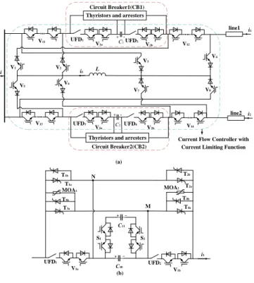
As shown in Fig. 1, the proposed CFC consists of a CFC with a current limiting capability and two CBs. Fig. 1(a) shows the topology of the proposed CFC and Fig. 1(b) shows the configuration of the two CBs. The CFC consists of two controllable capacitors (C1, C2) connected in two lines, an
inductor (L), eight IGBTs (V1 ~ V8) and their series connected
diodes, and four groups of series connected IGBTs (V11 ~ V14)
and their anti-paralleled diodes.
Taking CB1 as an example. It has two capacitors (C10, C20),
two bidirectional switches (S1, S2), two sets of auxiliary
switches (V1a, V1b) and their anti-paralleled diodes, two
ultra-fast disconnectors (UFD1, UFD2), four sets of anti-paralleled
thyristors (T1a, T1b),…, (T4a, T4b) and two arresters.
During normal operation, UFD1 and UFD2 are closed, V1a
and V1b are closed, (T1a, T1b),…, (T4a, T4b) are turned off, (S1,
S2) and (V1a, V1b) are turned on. In this case, the two CBs are
locked. The proposed circuit operates as a CFC. The CFC function will be immediately locked if a pole-to-ground fault is detected. Based on the discrimination of the faulted line and its current direction, the inductor L will be switched into the faulted line to limit the fault current by controlling V11~V14
and V1~V8. V1 V2 V3 V4 V5 V6 V7 V8 L V11 V14 V1a V1b V2b UFD1 UFD2 UFD3 UFD4 V12 C1 C2 line1 line2 i1 i2 V13 V2a
Thyristors and arresters
Thyristors and arresters Circuit Breaker1(CB1)
Circuit Breaker2(CB2)
Current Flow Controller with Current Limiting Function (a) V1b V1a T1a T1b T2a T2b T3a T3b T4a T4b UFD1 UFD2 + - i1 MOA1 MOA2 C10 M N + -C11 S1 S2 (b) i + -+ -iL
Fig. 1. Topology of the proposed CFC. (a) Overall structure diagram; (b) Structure of CB1.
B. Operating Principle of the Proposed CFC a. DC current flow control
The energy exchange between the inductor L and equivalent capacitors C1 and C2 is achieved by controlling V1~V8 and
therefore, resulting in the regulation of the current flows of lines 1 and 2. The positive direction of each current is shown in Fig.1. In the following analysis, when the current direction is negative, an increase of the current’s absolute value indicates a current increase. Moreover, it is assumed that the input current i is constant during the current flow controlling process. If i1 and i2 are in the same direction, the increase of
one current will lead to a decrease of the other, and vice versa. The operation will be described below if the directions of i1
and i2 are different.
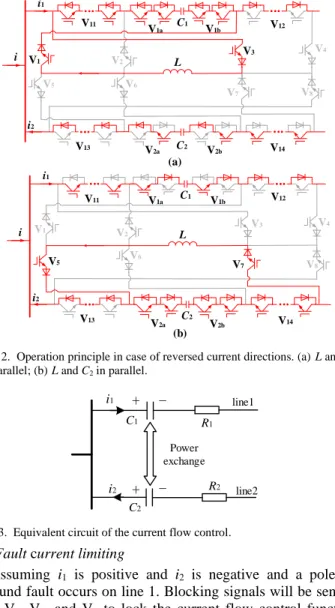
Taking i1 is positive and i2 is negative and i1 is being
increased as an example. First, turning on V1 and V3 to make
C1 and L parallel connected. In this case, C1 will charge L and
the current in L will gradually increase. The current direction of L is positive, as shown in Fig. 2(a). After a short period of time, C2 will be connected in parallel with L when V1 and V3
are turned off and V5 and V7 are turned on. In this case, L will
charge C2 and the current in L will gradually decrease and the
current direction is still positive, as shown in Fig. 2(b). The above process is performed once in one switching cycle and will be repeated at a high switching frequency in normal operation. In steady state, the voltages of the two equivalent capacitors remain constant. It is equivalent to deploying a voltage source in each line whose equivalent circuit is shown in Fig. 3.
3 V1 V2 V3 V4 V5 V6 V7 V8 L V11 V14 V1a V1b V2b V12 V13 V 2a i1 i2 (a) V1 V2 V3 V 4 V5 V6 V7 V8 L V11 V14 V1a V1b V2b V12 V13 V2a i1 i2 (b) C1 C2 C1 C2 i i
Fig. 2. Operation principle in case of reversed current directions. (a)L and C1
in parallel; (b)L and C2 in parallel.
+
-+
-i1 i2 line1 line2 Power exchange R1 R2 C1 C2Fig.3. Equivalent circuit of the current flow control.
b. Fault current limiting
Assuming i1 is positive and i2 is negative and a
pole-to-ground fault occurs on line 1. Blocking signals will be sent to V1, V3, V5, and V7 to lock the current flow control function
when the fault is detected. After a period of equipment delay, V11 will be turned off and V2 and V3 will be turned on. The
inductor L will then be switched in the faulted line 1 to limit the fault current. Current directions during the rising of the fault current are shown as the solid lines in Fig. 4. The fault current starts to decrease when it reaches the maximum value. In this case, the voltage of L is shown in Fig. 4. The fault current flows through the anti-parallel diode on V11, as
indicated by the dashed line, the inductor L is bypassed.
V1 V2 V3 V4 V5 V6 V7 V8 L V11 V14 V1a V1b V2b V12 V13 V2a i1 i2 C1 C2 + -i
Fig. 4. Operation of the fault current limiting.
Each converter station may feed current to the fault point, and the current on each line will increase. As shown in Fig. 4, C2 will be charged by the current i2. In this way, C2 helps to
reduce the current feeds to line 1 . c. Fault currentclearance
Assuming the output current of the converter station is positive and the fault occurs on line 1. There are two different conditions:
Condition 1: The initial direction of i1 is positive and the
current will remain positive after the fault. Condition 2: The initial direction of i1 is negative, after the fault, the current will
firstly decrease to zero and then start to increases in the opposite direction.
In both conditions, there are two status of the voltage uC1 on
C1: positive and negative. For condition 1, taking uC1 is
positive as an example, the operating processes are as follows: 1) In normal operation, the CFC controls current flows according to system requirements. UFD1 and UFD2 are closed,
V1a and V1b are turned on, as shown in Fig. 5 (a).
2) V1a and V1b will be turned off, T1a and T2a will be
triggered after detecting the fault. The current will be transferred to branch T1a and T2a. The current flows through C1
is zero. S1, S2 and UFD1, UFD2 are turned off, as shown in
Fig. 5 (b).
3) Once UFD1 and UFD2 are fully opened, T3a will be
triggered and it will be turned on due to the positive voltage. C10 begins to discharge, and the current will shifts from the T1a
branch to the T3a branch.
4) When the voltage of C10 drops to zero, it will continue to
be reverse-charged, and the capacitor voltage will increase continuously as shown in Fig. 5(c). MOA2 will be turned on
when the capacitor voltage reaches MOA’s critical voltage, as shown in Fig. 5(d). The fault current energy will be dissipated by the arrester. V1b V1a T1a T1b T2a T2b T3a T3b T4a T4b UFD1 UFD2 + - i1 MOA1 MOA2 M N + -S1 S2 (a) V1a V1b T1a T1b T2a T2b T3a T3b T4a T4b UFD1 UFD2 + - i1 MOA1 MOA2 M N + -S1 S2 (b) V1b V1a T1a T1b T2a T2b T3a T3b T4a T4b UFD1 UFD2 + - i1 MOA1 MOA2 M N + -S1 S2 (c) V1a V1b T1a T1b T2a T2b T3a T3b T4a T4b UFD1 UFD2 + - i1 MOA1 MOA2 M N + -S1 S2 (d) C10 C11 C10 C11 C10 C11 C10 C11
Fig. 5. Operation principle of the fault current clearance. (a) Stage I; (b) Stage II; (c) Stage III; (d) Stage IV.
If uC1 is negative in step 3), T4a will be triggered instead of
T3a and therefore, in step 4), MOA1 will be turned on. For
condition 2, if uC1 is positive, T1a, T2a, T1b and T2b will be
4 detected in step 2). Then, the following processes will be the
same as condition 1. The control diagram and the control sequences of the proposed CFC are illustrated in Fig. 6.
PI i1ref(i2ref) i1(i2) + - Campare PWM1 PWM2 (a) Carrier wave Fault occurs.
V11 is turned off and V2、V3are turned on.
T3a is triggered.
t0'
t0'
Current flow control
t1' t2' t3' t4' t5 ' t1' t2' t3' t4'
V1a、V1b、UFD2、 UFD1、S1、S2 are turned off and T1a, T2a are triggered.
V1~V8 are turned off.
(b)
Fig.6. Control of the proposed CFC. (a) Control diagram; (b) Control sequences.
III. THEORETICAL ANALYSIS OF THE OPERATION PROCESS
A. Theoretical Analysis of Current Flow Control
First, assuming i1 is positive and i2 is negative and increasing
i1 to analyze the current flow control. Based on Fig. 1, i1 can
be calculated as follows:
1 2
i = +i i . (1)
Assuming that the output current i of the converter station is constant. i1 will increase if | i2 | increases. Thus, the polarity of
the voltage of C2 is positive. If V1 ~ V8 are turned off, C2 will
continue to discharge to line 2. In order to maintain the stability of the capacitor energy, it is necessary to control the switches to perform energy transfer. If i1 is positive and i2 is
negative, the switches need to be controlled are V1, V3, V5,
and V7. V1 and V3 have a duty cycle of D, The switching of V5
and V7 are complementary. Assuming that the inductor current
is continuous, it can be deduced from the volt-second characteristic: 1 2 C C 1 D u D u − = . (2)
where uC1 and uC2 are the voltages of the capacitors C1 and C2
in the steady state. Then, the current flow of a DC gird with the proposed CFC can be analyzed as follows. Taking the four-terminal DC power grid shown in Fig. 7 as an example. Stations 1, 3 and 4 operate at constant power control modes. Station 2 controls the DC voltage. The proposed CFC is installed in the DC bus of station 1.
i12 ~ AC1 line1 line2 line4 line4 i31 i34 i24 AC DC DC reactor Station1 Station2 Station3 Station4 AC DC ~ AC3 DC AC ~ AC2 DC AC ~ AC4 DCCB Proposed CFC
Fig. 7. Diagram of the four-terminal DC transmission system.
The current flow can be calculated by (3), where u1, u2, u3,
u4 are the DC terminal voltages of the four converters, P1, P3,
and P4 are the power output from converters 1, 3, and 4 to the
DC-side, R12, R13, R34 and R24 are the resistances of lines
1,2,3,4; i12, i13, i34 and i24 are the currents of lines 1,2,3,4.
(
)
(
)
(
)
(
)
1 2 1 2 12 1 2 12 C 13 1 3 13 C 24 2 4 24 34 3 4 34 12 13 C Ci
u
u
u
R
i
u
u
u
R
i
u
u
R
i
u
u
R
u i
u i
=
− −
= − −
=
−
= −
= −
. (3)(
)
(
)
(
)
1 1 12 13 3 3 34 13 4 4 24 34 u i i P u i i P u i i P = + = − = − − . (4)It can be known from equations (2) and (3)
12 13 1 D i D i = − . (5)
B. Analysis of Fault Current Limiting and Clearance
In the four-terminal DC power grid, the analysis and calculation of fault currents will be very complicated. Therefore, a simplified model with one equivalent converter is used to analyze the fault current limiting and interrupting of the proposed CFC. The equivalent circuit is shown as Fig. 8.
In Fig. 8, udc is the equivalent DC voltage source of the
converter station, RS is the equivalent resistor of the converter
station, Ldc is the DC reactor, and Rl and Ll are the equivalent
resistor and inductor of the line. In this circuit, the current flow control cannot be performed. Before the fault occurs, the capacitor C10 is pre-charged to u0 to emulate the steady state
operation.Before the fault occurs, V11 and V1b are turned on,
5 T2b V1b T1a T2a T3a T3b T4a T4b UFD1 + -i12 MOA1 MOA2 V11 V2 V3 L Ldc RS udc + -Rl Ll iL A B C10 T2a
Fig. 8. Diagram of a test circuit.
TABLE I
SEQUENCES OF THE CURRENT LIMITING AND CLEARANCE
PROCESSES
Time Current limiting and clearance processes
t0 Fault occurs.
t1 The fault is detected.
t2 V1b, UFD1 are turned off and T1a, T2a are triggered.
t3 Current-limiting inductor is put in.
t4 T3a is triggered
t5 The fault current is at its peak
t6 Arrester acts
1) t0~t3
The current starts to rise when the fault occurs at t0. The
pre-fault value of the current is I0. At t2, the devices start to
operate. The on-state voltage drops of V11 and V1b are ignored.
During the period of t0~t2, the fault current i12 is expressed as:
( 0) 0 dc 0 0 12 s l 1 e t t u i I I R R − − = + − − + , (6)
where τ0 is defined as:
dc l 0 s l =L L R R
+ + .Starting from t2, and the current is transferred from the
branch of V1b, UFD1 and UFD2 to the branch of T1a and T2a.
During the period of t2~t3, regardless of the thyristor on-state
power losses, the current is still expressed as equation (6). 2) t3~t4
At t3, the current-limiting inductor L is connected to the line,
and the instantaneous magnetic flux is expressed as:
( ) (
) ( )
( ) (
) ( )
dc l 3 12 3 dc l 3 12 3 t L L i t L t L L i t − − + + = + = + + (7)It can be obtained from equation(7) that
( )
dc l( )
12 3 12 3 dc l = L L i t i t L L L + + ++ − (8)The current i12 will suddenly change when L is inserted into
the circuit. After t3+, L is fully inserted into the line. It can be
obtained from KVL that
(
)
12(
)
dc l s l dc 12 d i u L L L R R i dt = + + + + . (9)The value of i12(t3+) can be obtained from (6) and (8).
Substituting it into (9), the line fault current i12 is expressed as
( )
( )
( 3) 1 1 12 12 3 12 3 1 e t t i i t I i t − − + + = + − − , (10)where all the variables are defined as:
dc l 1 s l dc 1 s l =L L L R R u I R R
+ + + = + . 3) t4~t6At t4, T3a is triggered. After T3a is turned on, the voltage of
C1 is imposed on both ends of T1a making it withstand the
reversed voltage. The anode current drops rapidly, and C1
starts to discharge. Due to the negative voltage provided by C1,
T1a will be automatically turned off when the current in it
becomes zero. Then C1 will be reversely charged until the
arrester is triggered at t6.Ignoring the on-state voltage drop of
the thyristor during the period of t4~t5, it can be obtained from
KVL and KCL that ( )
(
(
)
)
(
)(
)
( )(
(
)
)
4 10 4 2 2 C 1 2 4 1 dc 2 2 2 2 12 10 1 2 4 2 sin sin e t t t t u d d e t t u i C d d t t
− − = + − + − = + + − + , (11)where all the variables are defined as:
(
)
(
)
(
(
)
)
( )
s l dc l 2 s l 2 dc l 10 dc l 12 4 1 10 1 0 dc 2 10 1 1 2 1 1 2 2 1 = 2 1 4 , tan , tan R R L L L R R C L L L L L L i t d C d u u d C d d d d d d
+ − + + + = − + + + + + = + = − + = = − At t5, the fault current reaches its maximum, and then the
inductor L is bypassed. During the period of t5~t6, the
inductance in the circuit is changed from Ldc + L1 + L to Ldc +
L1. The capacitor voltage and fault current can be obtained by
taking the new inductance into equation (11). 4) t6<t
At
t
6, the arrester operates with a clearance time of ∆
t
.
The energy dissipation process of the arrester is
simplified. The voltage across the arrester is
approximately expressed as
ku
movn, where
u
movnis the
rated voltage of the arrester
and
k
is a constant calculated
6
based I-V characteristic of the surge arrester to emulate
arrester’s voltage. During ∆
t
, the following voltage
relationship can be obtained based on KVL:
12
dc 1 movn dc
(
L
L
)
d i
ku
u
dt
+
= −
+
, (12)The value of i12(t6) can be obtained from (11). Substituting
(11) into (12), i12 can be obtained as follows.
12 12 6 movn dc dc 1
( )
ku
u
t
i
i
t
L
L
−
=
−
+
. (13)C. The Selection of Parameters
Taking the capacitors C10 and C11 in line 1 as an example. It
can be seen from (11) that, during the fault current clearance process, a large capacitance will result in a slow charging speed and large fault current. During the current flow control, a large capacitance will help the system reach the steady-state quickly. To meet the above requirements, a structure of parallel capacitors C10 and C11 is designed, wherein the value
of C10 is small and the value of C11 is large. During the current
flow control, both C10 and C11 are in the circuit, which gives a
large capacitance. Only C10 is in circuit during the fault
current clearance process. In this study, C10 is set as 50 μF and
C11 is set as 750 μF.
The inductor L is put into the line during the fault current limiting stage to suppress the increase of the fault current. A large inductance would help the suppression but may also have negative impacts on system stability. In a 500 kV HVDC system, the current-limiting inductance has been selected as 0.3 H [19].
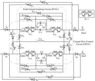
IV. THEH-BRIDGE INTER-LINE CFC WITH FAULT
CURRENT LIMITING CAPABILITY
A. Topology of the Proposed H-bridge Inter-line CFC
The proposed CFC requires a large number of IGBTs during the fault current limiting process. Therefore, an H-bridge inter-line CFC uses thyristors is proposed. The topology is shown in Fig. 9. This topology includes H-bridges consisting of thyristors, the current flow control circuit (CFCC), and the fault current limiting circuit (FCLC). The thyristors T1~T4 and
T5~T8 form two H-bridges in two lines. The directions of the
currents i1 and i2 shown in Fig. 8 are defined as positive
directions. The thyristors T1 and T2 (T5 and T6) are turned on
if the current of line 1 (line 2) is positive. Otherwise, the thyristors T3 and T4 (T7 and T8) are turned on. In this way, the
current flowing through CFCC and FCLC is always positive. The CFCC consists of four IGBTs (V1~V4) and their series
connected diodes, four capacitors (C10, C11, C20, C21), inductor
Llim, four auxiliary bidirectional switches (V1a, V2a, V1b, V2b),
four ultra-fast disconnectors (UFD1~UFD4), and four
bidirectional switches (S1~S4). The FCLC of the two lines
shares some components with the CFCC. Except for the four IGBTs (V1 ~ V4) and their diodes, the rest of the devices also
belongs to the FCLC. In addition, the FCLC includes 14 thyristors (T1a ~ T7a, T1b ~ T7b) on two lines.
Llim C10 C20 T1 T2 T3 T4 T5 T6 T7 T8 T1a T2a T3a T4a T5a T6a T7a T1b T2b T3b T4b T5b T6b T7b UFD2 UFD1 V1a V2a UFD4 UFD3 V1b V2b V4 V3 V1 V2 i2 i1 line1 Fault Current Limiting Circuit (FCLC)
C11 S1 C21 S3 S4 S2 S1~4
Current Flow Control Circuit (CFCC) line2 + -+ -+ -+ +
-Fig. 9. Topology of the proposed new inter-line CFC.
There are two differences between the second topology and the first one. First, the second topology uses H-bridges which achieve a single current direction of CFCC and FCLC, resulting in the reduce of devices. Second, the latter only uses thyristors in the FCLC without involving IGBTs. The capacitor voltage is used to control the thyristors for current limiting. The proposed inter-line CFC does not have a fault current interrupting capability.
B. Operating Principle of the Proposed H-bridge Inter-line CFC
During normal operation, T1a ~ T7a, T1b ~ T7b are turned off,
UFD1 ~ UFD4 are closed, V1a, V2a, V1b, and V2b are turned on,
the two lines are flow-controlled. The principle of current flow control of this CFC is similar to the processes described in Section II, and therefore, is not repeated here.
(a) Llim T5a T 6a C10 T1a T2a T3a T4a T7a UFD2 UFD1 V1a V2a C11 S1 S2 + -+ -Llim T5a T 6a C10 T1a T2a T3a T4a T7a UFD2 UFD1 V1a V2a C11 S1 S2 (b) + -+ -Llim T5a T 6a C10 T1a T2a T3a T4a T7a UFD2 UFD1 V1a V2a C11 S1 S2 (c) + -+ -Llim T5a T 6a C10 T1a T2a T3a T4a T7a UFD2 UFD1 V1a V2a C11 S1 S2 (d) + -+
-Fig. 10. Operation principle of the fault current limiting. (a) Stage I; (b) Stage II; (c) Stage III; (d) Stage IV.
V1 to V4 are turned off if a pole-to-ground fault occurs in
either line. The thyristors are controlled to switch the inductor Llim into fault current limiting. Assuming the fault occurs in
7 There are also two operating conditions as presented in
Section II. For the first condition, the fault current limiting processes are shown in Fig. 10 in the case that the voltages of C10 and C11 are positive. The fault current begins to decay
when the DCCB of line 1 operates. Then, the voltage of Llim
reverses, T7a is turned on and the inductor Llim is bypassed.
V. SIMULATION AND VERIFICATION
A. Validation of Proposed CFC a. Test in the equivalent circuit
The test circuit shown in Fig. 8 is built in PSCAD/EMTDC V4.5 with a simulation time step of 20 µs. The parameters are given in TABLE II. The fault occurs at t = 0.5 s. The simulation results of the fault current are compared with the analytical calculation conducted in Section III. The results are shown in Fig. 11. TABLE II CIRCUIT PARAMETERS Parameters Values udc, u0 [kV] 500,10 Rs, Rl, R0 [Ω] 2, 3, 3000 Ldc, Ll, L [mH] 150, 50, 300 C10 [μF] 50 I0 [kA] 2 0.5 0.504 0.508 0.512 0.516 0.52 0 2 4 6 8 10 t(s) i( kA ) Theoretical value Simulation value t0 t1 t2 t3 t4 t5t6
Fig. 11. Comparison between analytical calculation and simulation.
It is seen that the analytical calculation and the simulation match well during the period of t0~t6 before the arrester acts.
This verifies the correctness of the theoretical analysis in Section III. There is a slight difference between the two results because of the use of a simplified resistance of the arrester. b. Test in a four-terminal HVDC grid
The parameters of the four-terminal DC grid shown in Fig. 6 and CFC are given in Table III.
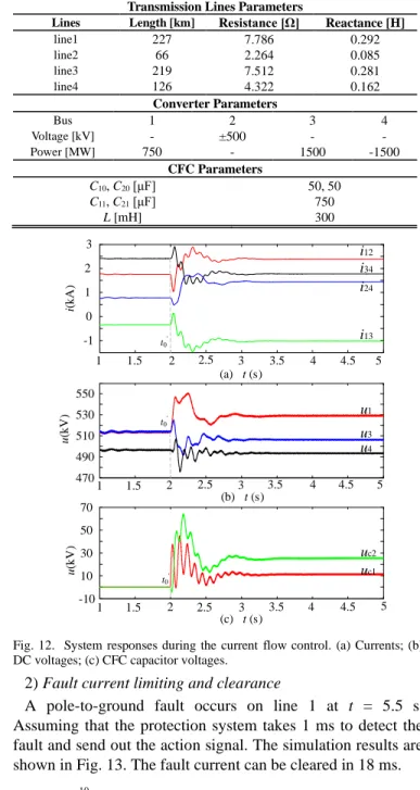
1) DC current flow control
The current of line1 (i12) is controlled to 2.40 kA at t = 2 s.
The simulation results are shown in Fig. 12. The voltages and currents changed when the current flow is triggered. Then the system becomes stable. The current i12 reaches the target value
0.8 s later with a smooth transient process. The voltages of the converter do not experience large fluctuations. It is seen that the capacitor voltages fluctuate greatly during the transient process. It is because their capacitances are small. However, it has small effects on the overall system operation. The
simulation results show that the CFC can control the current flow quickly and stably.
TABLE III
PARAMETERS OF THE FOUR-TERMINAL DC GRID AND CFC
Transmission Lines Parameters
Lines Length [km] Resistance [Ω] Reactance [H]
line1 227 7.786 0.292 line2 66 2.264 0.085 line3 219 7.512 0.281 line4 126 4.322 0.162 Converter Parameters Bus 1 2 3 4 Voltage [kV] - ±500 - - Power [MW] 750 - 1500 -1500 CFC Parameters C10, C20 [μF] 50, 50 C11, C21 [μF] 750 L [mH] 300 1 1.5 2 2.5 3 3.5 4 4.5 5 -1 0 1 2 3 i12 i34 i24 i13 (a) t (s) i (kA ) t0' 1 1.5 2 2.5 3 3.5 4 4.5 5 470 490 510 530 550 u (kV ) (b) t (s) u1 u3 u4 t0' 1 1.5 2 2.5 3 3.5 4 4.5 5 -10 10 30 50 70 u (kV ) (c) t (s) uc2 uc1 t0'
Fig. 12. System responses during the current flow control. (a) Currents; (b) DC voltages; (c) CFC capacitor voltages.
2) Fault current limiting and clearance
A pole-to-ground fault occurs on line 1 at t = 5.5 s. Assuming that the protection system takes 1 ms to detect the fault and send out the action signal. The simulation results are shown in Fig. 13. The fault current can be cleared in 18 ms.
5.498 5.502 5.506 5.51 5.514 5.518 -2 0 2 4 6 8 10 i (kA ) t(s) i12 iT1a iL iMOA2 iMN t1' t2' t3' t4' t5'
8 To verify the effectiveness of the current limiting, tests have
been conducted with and without triggering the current limiting mode. As shown in Fig. 14, the fault current is immediately reduced by 58.87% after triggering the current-limiting mode. The peak fault current is reduced by 27.78% as well. The CFC has good fault current limiting and interrupting capabilities 5.498 5.502 5.506 5.51 5.514 5.518 0 2 4 6 8 10 12 14 i (kA ) t(s)
Fault current limiting and clearance Fault current clearance
without limiting 27.78% 58.87% t1' t2' t3' t4' t5'
Fig. 14. Verification of current limiting effect.
c. Comparison with existing methods
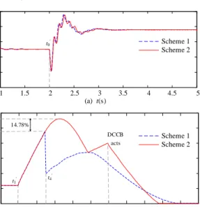
The proposed CFC (Scheme 1) has been compared with the inductor sharing inter-line CFC proposed in [25] and the hybrid FCL proposed in [19] (Scheme 2). The comparison of the two schemes uses the same parameters. Simulation results are shown in Fig. 15.
1 1.5 2 2.5 3 3.5 4 4.5 5 0.5 1 1.5 2 2.5 3 (a) t(s) i 12 (k A ) t0' Scheme 1 Scheme 2 5.498 5.502 5.506 5.51 5.514 5.518 0 2 4 6 8 10 12 (b) t(s) i 12 (k A ) t1' t4 ' DCCB acts Scheme 1 Scheme 2 14.78%
Fig. 15. Comparison of the proposed CFC with the other scheme. (a) Current flow control capability; (b) Fault current limiting and interrupting capability.
It can be seen from Fig. 15(a) that both schemes have excellent performance in current flow control. From Fig. 5(b), the peak current of Scheme 1 is 9.57 kA which is 14.78% lower than Scheme 2’s 11.23 kA. Moreover, the fault current under Scheme 1 is still less than Scheme 2 during the current limiting and dissipating periods.
B. Verification of Proposed H-bridge inter-line CFC
The proposed H-bridge inter-line CFC is deployed in the DC bus of station 2 of the DC power grid shown in Fig. 6. The parameters of inter-line CFC are: Llim =300 mH, C10=C20= 50
mF, C11=C21= 750 mF. At t = 5 s, a pole-to-ground fault
occurs on line 4. FCLC performs and cooperates with DCCB on line 4 to interrupt the fault current. The simulation results are shown in Fig. 16. The fault current can be limited to 7 kA and be cleared in 13 ms. 4.998-1 5 5.002 5.004 5.006 5.008 5.01 5.012 5.014 5.016 0 1 2 3 4 5 6 7 t(s) i( k A ) i24 -ic10 iDCCB iLlim iT7b Fault detect Fault current limiting DCCB acts and bypass of limiting inductor
Fig. 16. Currents of the fault current limiting process.
Fig. 17 illustrates the comparison of the fault current in three cases. In case 1, the DCCB acts without fault current limiting. The fault current limiting is triggered but Lim is not bypassed
in case 2. In case 3, the fault current limiting and Lim is
bypassed when DCCB acts. It is seen that the fault current value is reduced by 43.87% if the Lim is fully put into
operation when DCCB operates. It shows the proposed inter-line CFC has a good performance in current limiting. After the inductor Lim is bypassed, the falling rate of the fault current is
accelerated. The time taken to clear the fault current is reduced by about 3.6 ms. t(s) 4.998 5.002 5.006 5.01 5.014 5.018 0 2 4 6 8 10 12 Only DCCB acts i (kA ) Current limiting and inductor not
bypassed Current limiting and
inductor bypassed 43.87%
3.6ms
Fig. 17. Comparison of fault currents in three cases.
VI.CONCLUSIONS
In this paper, a CFC with DC fault current limiting and interrupting capabilities has been proposed. The topology, operation process and theoretical analysis are presented. The proposed CFC can perform current flow control on two lines during the normal operation. During the fault clearance process, the capacitor voltage is used to control the switching of thyristors to interrupt the fault current. It can effectively limit the rising rate and the peak value of the DC fault current. In the case of a four-terminal DC grid, the fault current can be reduced by 58.87% and the peak value of the fault current can be reduced by 27.78% compared to the case without using the CFC.
To reduce the use of IGBTs in the proposed CFC, an H-bridge inter-line CFC with fault current limiting capability is proposed. This CFC uses thyristors during fault current
9 limiting, and bypasses the current-limiting inductor when the
DCCB function operates. The fault current value can be reduced by 43.87% when the DCCB function operates. Additionally, the time taken to clear the fault current can be reduced by about 3.6 ms.
REFERENCES
[1] T. An, G. Tang and W. Wang, "Research and application on multi-terminal and DC grids based on VSC-HVDC technology in China," High Voltage, vol. 2, no. 1, pp. 1-10, 3 2017.
[2] G. Li, J. Liang, F. Ma, C. E. Ugalde-Loo and H. Liang, “Analysis of Single-Phase-to-Ground Faults at the Valve Side of HB-MMC in HVDC Converter Stations,” IEEE Trans. Ind. Electron., vol. 66, no. 3, pp. 2444-2453, March 2019.
[3] B. Berggren, K. Lindén and R. Majumder, "DC Grid Control Through the Pilot Voltage Droop Concept—Methodology for Establishing Droop Constants," IEEE Trans. Power Syst, vol. 30, no. 5, pp. 2312-2320, Sept. 2015.
[4] D. Jovcic, M. Hajian, H. Zhang and G. Asplund, "Power flow control in DC transmission grids using mechanical and semiconductor based DC/DC devices," in 10th IET International Conference on AC and DC Power Transmission (ACDC 2012), Birmingham, 2012, pp. 1-6. [5] L. Yao, H. Cui, J. Zhuang, G. Li, B. Yang and Z. Wang, "A DC power
flow controller and its control strategy in the DC grid," in IEEE 8th International Power Electronics and Motion Control Conference (IPEMC-ECCE Asia), Hefei, 2016, pp. 2609-2614.
[6] M. Q. Khan, M. M. Khan, J. Huawei and Z. Yi, "DC power flow control in DC networks through DC/DC zero sequence blocking transformer," in 2017 IEEE 2nd Advanced Information Technology, Electronic and Automation Control Conference (IAEAC), Chongqing, 2017, pp. 1149-1153.
[7] Y. Jianyang, M. Q. Khan, Z. Yanwen, M. M. Khan and M. Ali, "HVDC bidirectional power flow using solid state transformer," in 2017 International Conference on Circuits, Devices and Systems (ICCDS), Chengdu, 2017, pp. 110-114.
[8] K. Rouzbehi, S. S. Heidary Yazdi and N. Shariati Moghadam, "Power Flow Control in Multi-Terminal HVDC Grids Using a Serial-Parallel DC Power Flow Controller," IEEE Access, vol. 6, pp. 56934-56944, 2018.
[9] E. Veilleux and B. Ooi, "Multiterminal HVDC With Thyristor Power-Flow Controller," IEEE Trans. Power Del. vol. 27, no. 3, pp. 1205-1212, July 2012.
[10] F. Xu et al., "A shunt type power flow controller for meshed DC grids," in 12th IET International Conference on AC and DC Power Transmission (ACDC 2016), Beijing, 2016, pp. 1-6.
[11] Y. Cao, L. Yao, B. Yang, Z. Wang and W. Chen, "A novel DC power flow controller for VSC-MTDC system," in International Conference on Renewable Power Generation (RPG 2015), Beijing, 2015, pp. 1-6. [12] G. Ning, W. Chen and X. Zhu, "A novel interline DC power flow
controller for meshed HVDC grids," in IEEE Energy Conversion Congress and Exposition (ECCE), Milwaukee, WI, 2016, pp. 1-7. [13] Y. Wu, H. Ye, W. Chen and X. He, "A Novel DC Power Flow
Controller for HVDC Grids with Different Voltage Levels," in 2018 International Power Electronics Conference (IPECNiigata 2018 -ECCE Asia), Niigata, 2018, pp. 2496-2499.
[14] Y. Wang and R. Marquardt, "A fast switching, scalable DC-Breaker for meshed HVDC Super Grids," in International Exhibition and Conference for Power Electronics, Intelligent Motion, Renewable Energy and Energy Management, Nuremberg, Germany, 2014, pp. 1-7. [15] A. Hassanpoor, J. Häfner and B. Jacobson, "Technical Assessment of
Load Commutation Switch in Hybrid HVDC Breaker," IEEE Trans. Power Electron, vol. 30, no. 10, pp. 5393-5400, Oct. 2015.
[16] M. Jangale and K. D. Thakur, "Optimum positioning of superconducting fault current limiter for wind farm fault current in smart grid," in 2017 International conference of Electronics, Communication and Aerospace Technology (ICECA), Coimbatore, 2017, pp. 312-316.
[17] C. Noh et al., "A Study on a Protection System for Low Voltage DC Distribution System based on Solid State Fault Current Limiter," in
TENCON 2018 - 2018 IEEE Region 10 Conference, Jeju, Korea (South), 2018, pp. 0404-0407.
[18] J. Liu, N. Tai, C. Fan and S. Chen, "A Hybrid Current-limiting Circuit for DC Line Fault in Multi-terminal VSC-HVDC System," IEEE Trans. Ind. Electron (2017):1-1.
[19] J. Xu, X. Zhao, N. Han, J. Liang and C. Zhao, "A Thyristor-Based DC Fault Current Limiter With Inductor Inserting–Bypassing Capability," IEEE Emerging and Selected Topics Power Electron, vol. 7, no. 3, pp. 1748-1757, Sept. 2019.
[20] S. Li, C. Zhao and J. Xu, "A new topology for current-limiting solid-state HVDC circuit breaker," in 2016 IEEE 2nd Annual Southern Power Electronics Conference (SPEC), Auckland, 2016, pp. 1-5.
[21] D. Keshavarzi, E. Farjah and T. Ghanbari, "Hybrid DC Circuit Breaker and Fault Current Limiter with Optional Interruption Capability," IEEE Trans. Power Electron, vol. 33, no. 3, pp. 2330-2338, March 2018. [22] J. Yin, Q. Huo, L. Wu, T. Wei and L. Han, "The Topology Research of
Series-Parallel Multifunction Composite Controller for DC Power Distribution Network," in IEEE 27th International Symposium on Industrial Electronics (ISIE), Cairns, QLD, 2018, pp. 80-86.
[23] A. Mokhberdoran, O. Gomis-Bellmunt, N. Silva and A. Carvalho, "Current Flow Controlling Hybrid DC Circuit Breaker," IEEE Trans. Power Electron, vol. 33, no. 2, pp. 1323-1334, Feb. 2018.
[24] O. Cwikowski et al., "Integrated HVDC Circuit Breakers With Current Flow Control Capability," IEEE Trans. Power Del, vol. 33, no. 1, pp. 371-380, Feb. 2018.
[25] J ZHANG, Q XU, A LUO, F MA and Z HE, "Inductor sharing interline DC power flow controller and its control method, " Automation of Electric Power Systems, vol 42, no. 23, pp.20-26, 2018.
Jianzhong Xu (M’14-SM’19) was born in
Shanxi, China. He received the B.S. and Ph.D. degrees from North China Electric Power University (NCEPU) in 2009 and 2014 respectively. Currently, he is an Associate Professor and Ph.D. Supervisor of the State Key Laboratory of Alternate Electrical Power System with Renewable Energy Sources, North China Electric Power University, China, where he obtained his Ph.D. degree in 2014. From 2012 to 2013 and 2016 to 2017, he was a visiting Ph.D. student and Post-Doctoral Fellow at the University of Manitoba, Canada. He is an Associate Editor of the CSEE Journal of Power and Energy Systems. He is now working on the Electromagnetic Transient (EMT) equivalent modelling, fault analysis and protection of HVDC Grids.
Xinyu Li was born in Shaanxi, China. She
received the B.S. degree in power system and its automation from North China Electric Power University in 2018, where she is currently working toward her master degree. Her research interests include HVdc grid operation and protection.
Gen Li (M’18) received the B.Eng. degree
in Electrical Engineering and its Automation from Northeast Electric Power University, Jilin, China, in 2011, the M.Sc. degree in Power Engineering from Nanyang Technological University, Singapore, in
10 2013 and the Ph.D. degree in Electrical Engineering from
Cardiff University, Cardiff, U.K., in 2018.
From 2013 to 2016, he was a Marie Curie Early Stage Research Fellow funded by the European Union’s MEDOW project. He has been a Visiting Researcher at China Electric Power Research Institute and Global Energy Interconnection Research Institute, Beijing, China, at Elia, Brussels, Belgium and at Toshiba International (Europe), London, U.K. He has been a Research Associate at the School of Engineering, Cardiff University since 2017. His research interests include control and protection of HVDC and MVDC technologies, power electronics, reliability modelling and evaluation of power electronics systems.
Dr. Li is a Chartered Engineer in the U.K. He is an Associate Editor of the CSEE Journal of Power and Energy Systems. He is an Editorial board member of CIGRE ELECTRA. His Ph.D. thesis received the First CIGRE Thesis Award in 2018.
Chengyong Zhao (M’05-SM’15) was born
in Zhejiang, China. He received the B.S., M.S. and Ph.D. degrees in power system and its automation from NCEPU in 1988, 1993 and 2001, respectively. He was a visiting professor at the University of Manitoba from Jan. 2013 to Apr. 2013 and Sep. 2016 to Oct. 2016. Currently, he is a professor at the School of Electrical and Electronic Engineering, NCEPU. His research interests include HVDC system and DC grid.