Ashish Thapliyal
School of Electrical Engineering
Thesis submitted for examination for the degree of Master of Science in Technology. Espoo 12-08-2016 Thesis supervisor: Olav Tirkkonen Thesis advisor: Tommi Jokela
Author: Ashish Thapliyal
Title: Mobility Robustness in 5G Networks
Date: 12-08-2016 Language: English Number of pages: 9+49 Department of Communications and Networking
Professorship: S-72
Supervisor: Olav Tirkkonen Advisor: Tommi Jokela
5G is the 5th Generation of Mobile telecommunication system. 5G networks will cater to the needs of very diverse user equipment, from millions of stationary sensors per square kilometer to bullet trains running at over 500 km/h. Presence of users with such varied mobility requirements entails us to build a robust mobility architecture for 5G.
Two of the important requirements for 5G networks are a lower latency and a higher reliability than in existing generations of mobile networks. To accomplish the above mentioned use cases and requirements of 5G networks, the mobility solutions and their robustness become a very critical part of 5G. In this thesis we have studied the existing LTE networks, and keeping them as a baseline, tried to find solutions for mobility robustness in 5G networks.
The thesis discusses Mobility State Estimation (MSE) enhancements for dual and multiconnectivity. Analysis of mobility problems in using only one instance of mobility state for a multi-link, multi-layer connected UE are quantitatively analysed and a solution, which uses a MSE instance for each link in multi-link connectivity, is proposed.
Other mobility robustness topic that the thesis focuses upon is improvements in handover failure recovery mechanism, which can also be used for radio link failure in general. The thesis proposes a solution for re-establishment of RRC connection in 5G by using the RRC Connection Suspend and RRC Connection Resume procedure of Narrow Band Inter of Things (NB-IoT).
Keywords: 5G, Mobility, Mobility State Estimation, Dual Connectivity, Handover Failure, Radio Link Failure
Acknowledgement
This thesis is done as a part of Nokia’s 5G research project.
Foremost, I would like to express my sincere gratitude to my supervisor Prof. Olav Tirkonnen for his motivation, patience, immense knowledge and insightful comments which guided me throughout this work. I would also like to thank my instructor Mr. Tommi Jokela as well as Mikko Saily, who patiently, enthusiastically and smilingly clarified all my doubts. I would also like to thank my Handover Control team, Jari Sahinoja and Tarja Hiltunen from Nokia, who always supported and encouraged me during my thesis work.
I would also like to thank my parents, Mrs. Beena Thapliyal and Mr. U.S. Thapliyal, rest of my family and friends, for their love, understanding and inspiration. Last, but not the least, I owe a debt of gratitude to my wife Neha, for without her, I would not be able to make it.
Espoo, 12-08-2016
Contents
Abstract ii
Acknowledgement iii
Contents iv
Abbreviations vi
List of Figures viii
List of Tables ix
1 Introduction 1
1.1 Motivation . . . 1
1.2 Objective of the Thesis . . . 3
1.3 Structure of the Thesis . . . 3
2 Background 5 2.1 Cellular Network and its Evolution . . . 5
2.2 Heterogenous Cellular Network . . . 9
2.3 5G RAN Architecture . . . 10
2.4 Dual Connectivity and Multi Connectivity . . . 12
2.5 Mobility State Estimation . . . 15
2.6 RRC Connection Re-establishment . . . 19
2.7 RRC Connection Suspend and Resume Procedure . . . 22
2.8 Basic Definitions . . . 25
3 Mobility Robustness Problems in Current Cellular Networks 29 3.1 Handover region and Use of MSE . . . 29
3.2 Dual and Multi Connectivity and MSE . . . 32
3.3 Providing means to fulfill "Mobility on Demand" . . . 35
3.4 Optimization needs for re-establishment of radio connection . . . 35
4 Mobility Robustness Enhancements 37 4.1 Dual or Multi MSE . . . 37
4.2 The need for a new MSE State . . . 39
4.3 Re-establishing a RRC connection using RRC Resume Procedure . . 39
5 Conclusion 42 5.1 Summary . . . 42
5.2 Future Work. . . 43
A Appendix 48 A.1 Mobility Parameters for RRC Connected States . . . 48 A.2 Speed Dependent reselection parameters in RRC_IDLE State . . . . 49
Abbreviations
2G 2nd Generation of Wireless Telephone Technology 3G 3rd Generation of Wireless Telephone Technology 3GPP Third Generation Partnership Project
4G 4th Generation of Wireless Telephone Technology 5G 5th Generation of Wireless Telephone Technology 16-QAM 16-ary Quadrature Amplitude Modulation
64-QAM 64-ary Quadrature Amplitude Modulation AIV Air Interface Variant
BLER Block Error Rate
BTS Base Transceiver System CCCH Common Control Channel CE Control Element
CS Circuit Switched CN Core Network
C-RNTI Cell- Radio Network Temporary Identifier
DL Downlink
DRB Data Radio Bearer
EDGE Enhanced Data Rates for GSM Evolution eNB e-UTRAN Node B
E-UTRA Evolved Universal Terrestrial Radio Access Network FDMA Frequency Division Multiple Access
GERAN GSM EDGE Radio Access Network
GSM Global System for Mobile communications HOF Hand Over Failure
HSPA High Speed Packet Access
IMT International Mobile Telecommunications ISD Inter Site Distance
ITU International Telecommunication Union KASME Local Master Key in EPS
KeNB Key eNB, an intermediate Key at eNB Level Krrcint Key RRC Integrity Protection
LTE Long Term Evolution MAC Medium Access Control
MAC-I Message Authentication Code for Integrity MeNB Master eNB
METIS Mobile and wireless communications Enablers for the 2020 Information Society MIMO Multiple Input Multiple Output
MME Mobility Management Entity
mMTC Massive Machine Type Communication mmW Millimetre Wave
MSE Mobility State Estimation NAS Non Access Stratum
NCC Next Hop Chaining Counter NGMN Next Generation Mobile Networks NH Next Hop parameter in E-UTRAN
OFDMA Orthogonal Frequency Division Multiple Access PDCCH Physical Downlink Control Channel
PDCP Packet Data Convergence Protocol PS Packet Switched
RAN Radio Access Network RLC Radio Link Control RLF Radio Link Failure
RNC Radio Network Controller RRC Radio Resource Control
RSRP Reference Signal Received Power RTT Round Trip Time
SCH Shared Channel
SC-FDMA Single Carrier Frequency Division Multiple Access SeNB Source eNB or Serving eNB or Secondary eNB SINR Signal to Interference Ratio
SRB Signalling Radio Bearer
TDMA Time Division Multiple Access TeNB Target eNB
TR 3GPP Technical Report TS 3GPP Technical Specification TTT Time to Trigger
UE User Equipment
UICC Universal Integrated Circuit Card
UL Uplink
UMTS Universal Mobile Telecommunications System UTRAN Universal Terrestrial Radio Access Network V2V Vehicle to Vehicle communication
V2X Vehicle to Infrastructure communication VoLTE Voice over LTE
WCDMA Wideband Code Division Multiple Access WLAN Wireless Local Area Network
List of Figures
1 Cisco’s estimate of mobile data traffic growth rate [2] . . . 1
2 5G requirements [4] . . . 2
3 Voice Vs Data [8] . . . 7
4 LTE Architecture . . . 8
5 Example of a Heterogeneous Network . . . 9
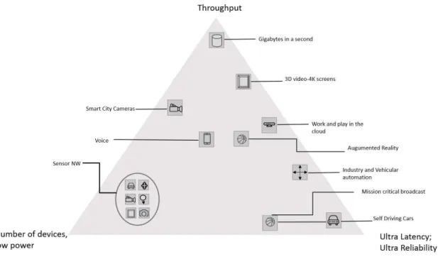
6 5G use cases [27] . . . 10
7 5G State Model [30] . . . 11
8 UL DL Imbalance issues in HetNet [19] . . . 12
9 Basic illustration of Dual Connectivity and Single connectivity UEs [19] 13 10 High level sketch of Dual connectivity showing how the data streams from CN might be divided at Macro and small cell [20] . . . 14
11 Dual Connectivity User plane architecture of 1A [19] . . . 14
12 Dual Connectivity User plane architecture of 3C [19] . . . 15
13 Multiconnectivity Scope for 5G [21] . . . 16
14 No scaling of parameters [26] . . . 18
15 Scaling of parameters Treselection [26] . . . 18
16 Scaling of parameters Treselection and Qhysteresis [26] . . . 19
17 RRC Connection Re-establishment in LTE . . . 21
18 RRC Connection Resume Procedure . . . 23
19 Preparation of short MAC-I . . . 24
20 Handover Region at cell border [35] . . . 29
21 UE’s handover or cell reselection with respect to Small cell and Macro cell . . . 33
List of Tables
1 Handover region of different pairing of cells for pathloss exponent 3.76 31 2 Time to cover the handover region with different UE speed . . . 31 3 Traffic Model . . . 34 4 Radio Link Failure Interruption time and User Experience [32] . . . . 36 5 Comparison of legacy RRC Connection Re-establishment procedure
of LTE with RRC Connection Resume procedure of 5G, when used for re-establishment of RRC connection . . . 41
The objective of this thesis is to find mobility robustness solutions for 5G networks. This introductory chapter first explains the motivation for this thesis and then briefly details about the objective of the thesis and concludes with outlining the structure of the thesis.
1.1
Motivation
Mobile technology has been growing with a rapid rate in the recent years. To put the numbers into perspective, mobile broadband connections will steadily increase in its global base from 40% in 2014 to 70% in 2020. It is estimated that from 2015 to 2020, 2.9 billion new smartphone connections will fuel the growth of mobile telephony. With the advent of new services and applications, the data traffic is going to see a tenfold increase from 2015 to 2019 [1]. In 2015, mobile data traffic globally increased by 73%. In the last decade mobile data traffic has grown 4000 times and in the last 15 years it has grown 400 million times [2]. In short, the need for more speed, ubiquitous coverage, and better quality is continuously growing. Figure 1 shows Cisco’s estimate of mobile data traffic growth by 2020.
Figure 1: Cisco’s estimate of mobile data traffic growth rate [2]
Mobile communication, as a technology, has also been evolving continuously to meet these demands. From analog signalling in 1st generation of mobile communication to the latest Long Term Evolution (LTE) or 4G technology, the telecommunication industry is trying to keep up the pace with the growing demand from the subscribers. So, Global System for Mobile communications (GSM), Universal Mobile Telecommu-nications System (UMTS), High Speed Packet Access (HSPA), and LTE are already in the field now. The development of LTE-Advanced, the evolution of 4G, is in the process of field trials and early rollouts [3].
Moreover, the definition of user equipment is not limited to traditional mobile phones anymore. A whole new set of devices are emerging on the horizon which will be connected to mobile networks. With the advent of massive machine type communication (mMTC) as well as Vehicle to infrastructure (V2X) and Vehicle to
vehicle (V2V) communication, the number of connected devices will increase manifold. Interestingly, these all devices come with very different sets of requirements.
For example, the main focus area for V2V communication is ultra-reliability and low latency, on the other hand for mMTC devices the focus is not so much on reliability or latency but on power efficiency. The requirement for mMTC devices is such that these devices should last for more than 10-15 years without their battery getting drained.
Figure 2 shows these diverse requirements and the devices that need them:
Figure 2: 5G requirements [4]
Such diverse requirements have increased the challenges for the future mobile commu-nication. Hence the need for a new mobile communication system, with even more enhanced capabilities than existing systems seems pertinent [3]. The expectation is that this 5th Generation (5G) system should be able to fulfil the above mentioned three most important requirements, i.e., throughput in the the scale of Gbps, virtually zero milli-second latency, and millions of devices per square Kilometre.
Previous mobile communication generations were mainly driven by higher system capacity and better spectral efficiency. 5G in contrast will be driven by network densification. Network densification was considered part of earlier generations of mobile communication as well, not as a design concept but as an add on feature [5]. Densification of the network is needed to cater to the high throughout and extremely low latency demands of 5G. The main idea is to let the access points be closer to
the users. By doing so, the Round Trip Time (RTT) of the radio will reduce and the network throughput will increase as data can be handled locally by many sub networks created by these small cells. Small cells are expected to provide most of the data traffic by 2020 [6].
With these Ultra Dense Networks (UDN), one of the challenges will be to meet the above mentioned requirements such as ultra-reliability and low latency when the user is moving. A moving user’s radio signals changes such that the user gets better signals from the cell it is about to enter (also called Target Cell ) than the cell which it is about to leave (also called Serving Cell).
The user’s radio resources should be moved from the source cell to the target cell in such a way that the user gets uninterrupted service or has the illusion of uninterrupted service. This process is called Handover in literature. Handovers become a problem when the user is moving fast, because the network gets very little time to execute the handover of the UE from source cell to target cell. When the cell sizes are small, like in ultra-dense networks in 5G, this problem will become very prominent. 3rd Generation Partnership Project (3GPP) has already acknowledged this problem with their study item on Mobility performance in Heterogeneous Network [7].
1.2
Objective of the Thesis
As discussed in the previous section, network densification will bring its own drawbacks in the 5G network. Not only the handovers will become more frequent, but also the time to execute them will be reduced. As a result, mobility in 5G is an important research topic. The research work in this thesis is aimed at studying mobility in 5G networks. The aim is to come up with methods and procedures which will make the mobility in 5G robust.
The two mobility topics, which this thesis concentrates on, are Mobility State Estimation Enhancement and Radio Link Failure Enhancement. The thesis first evaluates the problems in the current mobility state estimation method by performing a quantitative analysis. Based on the finding of this analysis a solution is provided that will enhance the current algorithm. Another topic that is the focus of this thesis is the latency and robustness in radio link failure. For this purpose, existing radio link failure procedure in LTE is examined and then a solution is proposed that aims to reduce the latency in radio link failure scenarios in 5G networks.
1.3
Structure of the Thesis
The thesis has been organized into five Chapters. Chapter 2 starts with a brief overview of cellular networks and their evolution. It is envisioned that 5G will be an amalgamation of different wireless technologies such as LTE and Wireless Local
Access Networks (WLAN), and it will also be a network having cells of various sizes. Accordingly, moving further in Chapter 2, there is a brief introduction to Heterogeneous Networks. Next, 5G Radio Access Network (RAN) architecture is discussed. This is followed by an introduction to Dual Connectivity and Multi Connectivity. Chapter2continues with a discussion of different proposed architectures for Dual connectivity in LTE. The discussion then moves to Mobility State Estimation and how it affects the mobility decisions in existing networks, with LTE as an example. Radio Resource Control (RRC) Connection Re-establishment procedure is explained briefly as the next subtopic. The discussion then moves to explanation of RRC Connection Suspend and Resume procedure. At the end of Chapter 2, a brief list of basic definitions, used extensively in this thesis, is provided.
Chapter3discusses the problem statements for which this thesis tries to find solutions. The first section discusses the problem of Mobility State Estimation with Dual Connectivity and Multi Connectivity architecture. The next section discusses the need of a new Mobility State Estimation parameter and the chapter concludes with the discussion on need for latency improvement for handover failure/radio link failure scenarios in 5G networks.
Chapter 4discusses the solutions proposed for the problems discussed in the earlier chapter. The advantages of the dual mobility state estimation are discussed through an quantitative analysis and advantage of the use of the RRC Resume procedure in re-establishment of RRC connection is analysed considering latency improvements. Chapter5 concludes the thesis. It discusses the conclusions drawn from this thesis work and also discusses, in brief, the potential future works.
2
Background
This Chapter prepares the foundation for this thesis. It starts by giving a historical introduction of cellular networks and then goes on to explain the building blocks on which this thesis is based.
2.1
Cellular Network and its Evolution
A cellular network comprises of a Radio Access Network (RAN) and a Core Network (CN). The Radio Access Network is the part which implements the access technology. The multiple access technique in GSM is Frequency Division Multiple Access (FDMA), and Time Division Multiple Access (TDMA), in UMTS it is Wideband-Code Division Multiple Access (W-CDMA) and in LTE (4G) it is Orthogonal Frequency Division Multiple Access (OFDMA) and Single Carrier - Frequency Division Multiple Access (SC-FDMA). The Core Network is the switching centre, the link of RAN to the
outside world like Internet and Public Switched Telephone Network.
The RAN comprises of User Equipment (UE), Base Transceiver Stations (BTSs) and also sometimes controller devices that control these BTSs, e.g., Base Station Controllers (BSCs) in GSM and Radio Network Controllers (RNCs) in UMTS. The BTS enables the wireless connection between the UE and the Radio Network. A Base Station is also the network entity that creates the "cell" in the cellular network. A typical base station has many transceivers so that the base station is able to serve varied frequencies in a cell.
A base station serves one or more cells. Because the base station is power limited, it can serve only a limited area, hence the frequency that the base station is using can be re-used in another base station. Since 3G, this re-use factor of frequency is 1 i.e. all the neighboring base station can use the same frequency.
As described above, the Core Network is a switching centre and it is the gateway for the RAN towards the outside network. The Core Network routes user sessions between RANs and other networks. Other important functions of Core Network are, billing, authentication and call control.
The first predecessors to mobile telephone systems were launched in 1946 by Bell Labs. These systems used transmitters which had very high power and analog FDMA techniques. The coverage was around 50 miles and there were only very few customers due to bandwidth constraints.
To overcome this bandwidth problem, Bell labs invented the cellular concept. The 1st Generation of mobile networks, which used this cellular concept, were introduced in Nordic countries around the late 1970s. These systems were analog in nature. Examples of 1G systems are Nordic Mobile Telephone (NMT), Advanced Mobile Phone System (AMPS) and Total Access Communication System (TACS).
This "cellular" concept was later shortened to "cell". The name was coined because of the way the signals are handed over between towers. The network itself is distributed into areas called cells.
The inefficiency of analog, non-global 1G system led the development of 2G mobile networks. 2G systems were launched in late 1980s and early 1990s. Data services with low bitrates were supported in conjunction with voice calls.
If we compare the second generation of mobile networks with the first generation of mobile networks, the main difference is that second generation systems were using digital multiple access technologies. 2G technologies are divided into Time Division Multiple Access (TDMA) and Code Division Multiple Access (CDMA) depending on the multiplexing used by the system.
Even with 2G telecommunication systems, multiple standards were used worldwide for mobile communications. Some standards were only used in one region or in one country and were incompatible with each other. GSM emerged as the most successful family of 2G mobile networks. It is estimated that more than 80% users of 2G are on GSM. GSM was first commercially launched in Finland in 1991.
The data handling capabilities for 2G mobile systems were limited. So the Third Generation systems were needed to provide high bit rate services that enable high quality images and videos to be transmitted and received and to provide the access to the web with high data rates [11].
With the meeting of World Administrative Radio Conference (WARC) in 1992, the development of 3rd Generation of cellular systems started. WARC was an International Telecommunication Union (ITU) technical conference and in 1993, its name was changed to World Radio Conference (WRC). It was decided that frequencies around 2000 MHz can be used for 3G systems.
The 3G systems were called International Mobile Telephony 2000 (IMT-2000) within ITU. Several technologies were defined within IMT-2000 for 3rd generation of mobile telephony, the most prominent of those were:
• IMT- DS, Direct Sequence. Also known as W-CDMA or UTRA-FDD, used in UMTS
• IMT-MC, Multi-carrier, Also known as CDMA 2000, the successor of 2G CDMA (IS-95)
• IMT-TD Time-Division TD-CDMA and TD-SCDMA
UMTS was the most prominent of all these technologies. UMTS was an evolution of GSM. The core network was not changed drastically but the main change was in the air interface.
UMTS air-interface used W-CDMA (Wideband Code Division Multiple Access). The 5MHz bandwidth was chosen because it was sufficient for providing 384Kbps speed, which was one of the requirement of IMT 2000. In addition, the wide carrier bandwidth of W-CDMA offered increased multipath diversity [11].
Commercially UMTS network was first opened in Japan in early 2000-2001 and in Europe it was launched around 2002. In 2004, more UEs that support W-CDMA were launched to market and that was the timeframe when we could say that UMTS was really operable.
As can be seen from the Figure 3, the trend in the traffic was skewed more heavily towards data traffic than towards voice traffic. So the work on a new technology started as early as in 2004 (even before the commercial release of HSPA services). This led to the discussions in 3GPP on the new radio technology or 4G.
Figure 3: Voice Vs Data [8]
International Mobile Telecommunication - Advanced (IMT- Advanced) is a concept document for mobile technologies beyond IMT-2000. IMT-Advanced from ITU required the following from the 4G networks:
• An all IP based system
• A system which is interoperable with existing wireless standards.
• Data rate (peak) of 100 Mbps for users with high mobility and a peak data rate of 1Gbps for low mobile users.
• Scalable channel bandwidth requirements. • Seamless connectivity and global roaming.
Only two candidates were submitted against these requirements for IMT-Advanced. Those were Worldwide Interoperability for Microwave Access (WiMAX) and LTE. LTE specifications were developed by 3GPP and WiMAX specifications were devel-oped by the WiMAX Forum. LTE is the more popular of the two standards and further discussion has its focus on LTE.
LTE uses OFDMA for downlink and SC-FDMA for uplink. There are few important aspects of OFDMA that makes it so important. They are following [13]:
• Robust against Inter Symbol Interference (ISI) effectively. • Good spectral properties.
• Network capacity can be increased by increasing the carrier bandwidth. • Low complexity receiver implementation.
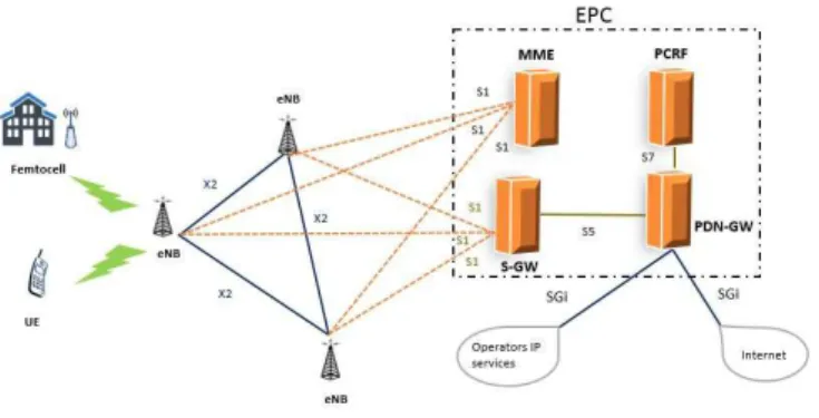
With the evolution of the air interface, it became clear very soon that that the system architecture also needs to be evolved. The consensus towards optimizing the system for packet services was one of the strongest reasons for an evolution of the system architecture. As macro-diversity gains were not relevant for LTE, the centralized controller was not needed, which led to a flat architecture. All the functionality related to communication over air were moved to eNB, which is the transmitting and receiving network node [10]. The LTE architecture is depicted in Figure4.
The main reason for moving to an all IP network was to provide the same platform for all new technologies and also to harmonize the experience of the user [12].
Figure 4: LTE Architecture
The first commercial launched LTE network was opened by TeliaSonera in Stockholm as well as in Oslo in late 2009. LTE release 8 reached a peak data rate of 150 Mbps
in DL and 50 Mbps in UL with 2*2 MIMO and 16QAM in UL. With 4*4 MIMO the speed in DL could go to theoretical maximum of 300 Mbps in DL and 75 Mbps in UL with 64 QAM [13]. LTE later evolved into LTE- advanced with release 10 onwards. The DL speed is predicted to be 1 Gbps and UL to be 500 Mbps.
2.2
Heterogenous Cellular Network
As discussed in Section1.1, the data rate over cellular network is seeing an exponential growth. The number of mobile data subscribers is increasing and the services which need very high bandwidth are competing for the same radio resources.
Operators have been trying to keep pace with this steep growth of data by improving upon the radio access capability of current sites by the addition of new radio spectrum, multi antenna techniques and more efficient modulation techniques [14] [15].
However, at some point in future the capacity offered by above mentioned evolved radio access will not suffice the need of the users. One alternative path, to meet this demand of huge capacity, is the densification of the network [14].
Addition of various kind of small cells and integrating them tightly with the macro sites will help in maintaining performance, balance the load of the network and improve the quality of service while efficiently re-using the spectrum. The primary reason for adding small cells is to increase the capacity of the networking hot spots and also to improve the coverage, for example, at cell borders or at some blind spots. Such mix of small cells and macro cell is called Heterogeneous Network or HetNet. Figure 5 is an example of HetNet containing femto cells, remote radio heads, and pico cells within a macro cell site.
Figure 5: Example of a Heterogeneous Network
of the telecommunication networks. Apart from the capacity of users in small cells, user performance in macro cell also improves when small cells are used to fill the coverage holes in macro cells [18].
2.3
5G RAN Architecture
The key service types for 5G as defined in [27], [28], [29] are:
• Extreme Mobile Broadband (xMBB): It is forecast that 3GPP would support user’s experienced data rate up to Gpbs level and peak data rate up to tens of Gpbs. The traffic volume in an area could be around Tbps per square Kilometer.
• Massive Machine Type Communication (mMTC): It is forecast that billions of network enabled devices will require wireless connectivity. These devices will consist, among other things, such low power devices whose battery life is estimated to be 10-12 years.
• Ultra-reliable/Critical machine type Communication (uMTC): The use cases like e-health services or critical infrastructure communication require ultra-reliable communication. End to end latency for few of these services may be very low and reliability very high.
Figure 6: 5G use cases [27]
Based on these service types, METIS-II has derived requirements for 5G RAN. Some of those requirements are [29]:
• Scalability of 5G RAN: Scaling to extremes is one of the key 5G design requirements.
• Native support of multiconnectivity and device to device communication. • Future proof: 5G RAN should be designed such that it is future proof which
means that new features and requirements could be added to 5G efficiently. • Energy Efficiency: RAN design of 5G should be energy efficient.
5G use cases, as shown in Figure 6, are developed by NGMN, and are grouped into eight families [27].
To fulfil these diverse requirements of 5G, for example, data rates of the scale of Gbps, latency of the scale of few milliseconds, and battery power efficiency, it is proposed that 5G Radio Access Network will have one more state as compared to LTE, called “Connected Inactive” [29]. The proposed state model for 5G RAN is shown in Figure 7.
Figure 7: 5G State Model [30]
The most frequent state transition in this 5G RAN state model is foreseen to be from RRC_CONNECTED to RRC_CONNECTED_INACTIVE. It is predicted that state transition from RRC_IDLE to RRC_CONNECTED will happen only during the initial access or later only as a fall back case when the network could not keep the call in RRC_CONNECTED or RRC_CONNECTED_INACTIVE [29]. The RRC_CONNECTED to RRC_CONNECTED_INACTIVE state transition is predicted to be most frequent state transition in 5G, as mentioned above. Accord-ingly this state transition should be kept lightweight and fast [29]. To achieve this, the RAN will keep the UE context when the UE makes a transition to RRC_CONNECTED_INACTIVE. The S1 connection (see Figure 4) will be main-tained. When the UE wants to resume the call in RRC_CONNECTED again, UE resumes with a "resume ID", which is provided when the connection is suspended. It is assumed that network will have the context of the UE. This makes the transition from UE’s sleeping state (RRC_CONNECTED_INACTIVE) to RRC_CONNECTED fast as the network does not need to set up a S1 connection. As the network al-ready has the UE’s context, the RRC Resume procedure can be a very lightweight procedure.
2.4
Dual Connectivity and Multi Connectivity
Although HetNets, discussed in Section 2.2, promise several benefits, they come with their own problems. Increased number of cells will increase the number of cell boundaries, hence an increase in cell (re-)selection and handovers. This will lead to higher signalling overhead. There is a significant difference in transmit power of small cells and macro cells, which will cause Uplink/Downlink power imbalance for UEs. For example, a cell which is not the serving cell for a UE may be the best Uplink cell for the UE.
In Figure8, macro eNB’s DL received power at the UE is depicted in green. Pico eNB’s DL received power at the UE is depicted in grey. UE’s UL received power at the macro eNB is depicted in purple. UE’s UL received power at the pico eNB is depicted in yellow. At UL cell border the received UL power from the UE is same at the two eNB, whereas at the DL cell border the DL signal power from the both the eNBs is the same at the UE. As can be seen from the figure that between UL cell border and DL cell border UE is in UL/DL imbalance i.e. the best UL and the best DL cell for the UE are different.
Figure 8: UL DL Imbalance issues in HetNet [19]
The high difference between the transmit power of small cells and macro cells may have a significant impact on performance of UEs near the cell edges. For example, it will impact the handover failure rates and also increase the ping-pong rates (rapid handover back and forth between two cells). So, a new architecture for HetNet scenarios which would mitigate these problems was envisioned [16].
Densification in co-channel deployment of small cells might cause much interference. One simpler approach used for densification of network is to deploy small cells at a
different frequency than macro cell. In 3GPP release 12, a new network architecture with split Control and User plane was introduced. In this architecture the Control Plane and User Plane are not necessarily handled by the same network node. So, small cells can be used to increase the capacity of users at hot-spots and macro cells are used to enhance the coverage. This kind of dual connectivity systems enhances the system performance as macro cells mostly handle the Control Plane messaging like mobility and paging and it may be possible for small cells to sleep for longer time, if there is no user which needs high capacity [16]. The macro eNB in a dual connectivity scenario is termed as Master eNB (MeNB) and the small cell’s eNB is termed as Secondary eNB (SeNB).
Figure 9: Basic illustration of Dual Connectivity and Single connectivity UEs [19]
This kind of architecture means that Control and User plane signalling might not be transmitted from the same network node [16]. Figure 9 illustrates UEs with single and dual connectivity.
Signalling bearer split, which is a concept that means that the Signalling Radio Bearer (SRB) can be split over multiple eNBs, instead of being transmitted from a single eNB, is not supported in LTE yet. In 3GPP several User plane bearer split architectures have been proposed. The agreement was to support two architecture 1A and 3C which are explained in the next paragraphs [17].
Both SeNB and MeNB can carry the same data bearer, split at RAN or they can carry separate bearers split at Core Network. The splitting of bearer can be performed both at downlink and uplink. So UE needs to maintain separate protocol stack for MeNB and for SeNB [17].
The architecture of 1A and 3C is shown in Figure 11 and 12. It can be seen from the figure that in architecture option 1A, bearers are split at S-GW. The MeNB and SeNB gets separate data bearers. In the option 3C of dual connectivity architecture, MeNB receives the S1-u bearer and then splits it between MeNB and SeNB. The UE, as mentioned above, maintains two separate protocol stacks.
Figure 10: High level sketch of Dual connectivity showing how the data streams from CN might be divided at Macro and small cell [20]
Figure 11: Dual Connectivity User plane architecture of 1A [19]
In 5G, this concept of dual connectivity is extended to multiconnectivity, such that a UE’s radio resources might be configured from more than two network nodes. As shown in Figure 13, 5G multiconnectivity will not only focus on aggregating the radio reseources from inter frequency cells, such as in Carrier Aggregation (CA) or in Dual Connectivity, but will also include the solutions that include aggregating
Figure 12: Dual Connectivity User plane architecture of 3C [19]
the radio resources from the cells operating on the same frequency, e.g., Joint Transmission/Dynamic Point Selection Co-ordinated Multipoint (JT/DPS CoMP) and multiflow. Multiconnectivity will inherit LTE dual connectivity specifications as well as develop new features and solutions to meet the very diverse requirements of different 5G use cases. For example, it is foreseen that because of requirements for ultra-reliability and ultra-low latency 5G multiconnectivity will also support Control Plane multiconnectivity [21].
It is envisioned that 5G multiconnectivity will have following capabilities [21]: • Control Plane multiconnectivity.
• Data duplication support for Ultra-reliable UEs. • Inter Radio interface optimization.
• Multiconnectivity support for high frequency bands. • Enabling more multiconnectivity options.
2.5
Mobility State Estimation
LTE supports UE’s moving with varying speeds. The UE can be anything from a pedestrian walking on sideways to a passenger in a bullet train which is moving at more than 300 km/h. Hence, the handover and cell change procedures also need to adapt to such varying UE speeds.
The RRC in LTE has two states RRC_IDLE and RRC_CONNECTED. The mobility is UE controlled in RRC_IDLE state and network controlled in RRC_CONNECTED
Figure 13: Multiconnectivity Scope for 5G [21]
state of LTE [22]. This means that in RRC_IDLE state UE makes the decision for cell selection or re-selection and updates the network. But in RRC_CONNECTED state the network makes the decision for handovers, based on UE’s measurement reports and other criteria like admission control, cell load etc.
Mobility State Estimation (MSE) is a method specified for LTE where the number of handover or cell reselection events defines the UE mobility state for RRC Connected and RRC Idle modes respectively. According to 3GPP TS 36.304 [25], a UE can be in three mobility states based on the number of cell selections (in RRC_IDLE State) or number of Handovers (in RRC_CONNECTED state):
• Normal Mobility State • Medium Mobility State • Fast Mobility State
The algorithms to calculate MSE in RRC_CONNECTED are given below [21]. In these algorithms,
n-CellChangeHigh is the number of cell changes that is needed to enter the mobility state High.
n-CellChangeMedium is the number of cell changes that is needed to enter the mobility state Medium.
T imeInterval ←t-evaluation
if N umberof Handover≥n-CellChangeHigh then
U E0sM obilityState←High
else
if N umberof Handover ≥n-CellChangeMedium then
U E0sM obilityState←M edium
else
U E0sM obilityState←N ormal
end if end if
Based on the calculated mobility state of the UE, the parameter such asTimeToTrigger (TTT), time for reselection (Treselection) and hysteresis marginQhyst are scaled. The basic idea is that to avoid ping-pong handover, the UE triggers handover only after the RSRP of the target cell is above the RSRP of the source cell by some offset and for some predefined time interval. This offset is called hysteresis margin and this predefined time interval is calledTimeToTrigger (TTT). This point, where RSRP of target cell is above the RSRP of source cell byQhyst for a predefined time interval TTT, is shown as point B in the Figure14.
sf-High and sf-Medium, in the algorithm below, are the scaling factors which are multiplied with the mobility parameters to scale the value of these parameter. According to 3GPP TS 36.331 [24], the values that sf-High or sf-Medium can take are 0.25, 0.5, 0.75 or 1.0.
if U E0smobilitystate=n-CellChangeHigh then
TimeToTrigger←TimeToTrigger×sf-High else
if U E0smobilitystate=M edium then
TimeToTrigger←TimeToTrigger×sf-Medium else
TimeToTrigger←TimeToTrigger
end if end if
These mobility parameters, such as,t-evaluation,t-hystNormal,n-CellChangeHigh, n-CellChangeMedium, and TimeToTrigger are explained in the AppendixA.1 [23]. In RRC_IDLE state the logic is analogic with a different time window and different parameters that are scaled. The parameters related to RRC_IDLE state are explained in Appendix A.2
The figures 14, 15, 16 show how a change in mobility state of a UE can affect the scaling of certain handover parameters and how this scaling effects the cell reselection
procedure [26]. Cell re-selection in this scenario happens when the equation, RSRP of target cell - RSRP of source cell ≥Qhyst,
is satisfied for a predefined time period Treselection.
Figure 14: No scaling of parameters [26]
Figure 14 shows the scenario when no scaling is used. RSRP of target cell becomes better than RSRP of source cell by Qhyst at point A. UE waits for a time period Treselectionand after that at point B in the figure, the UE triggers cell re-selection.
Figure 15 shows the scenario when the UE is either in High or Medium mobility state and scaling only for Treselection is used. RSRP of target cell becomes better than RSRP of source cell byQhyst at point A. The value of the parameter Treselection is scaled, so instead of triggering cell reselection at point B, UE triggers cell re-selection earlier at point C in the figure.
Figure 16 shows the scenario when the UE is either in High or Medium mobility state and the value of the parameter Qhyst is scaled together withTreselection. The equation for triggering cell re-selection now becomes,
RSRP of target cell – RSRP of source cell ≥ Qhyst (scaled). So, in Figure 16, reselection is triggered much earlier at point D.
Figure 16: Scaling of parameters Treselection and Qhysteresis [26]
The main advantage of scaling the mobility related parameters, like Treselection, Qhyst orTimeToTrigger, is that it facilitates faster execution of mobility procedure for UEs that are moving with high speeds. A UE, which is fast moving, should be facilitated such that it can trigger handovers earlier than UEs which are slow moving, otherwise fast moving UE would have entered deep inside the boundaries of target cell before the handover signalling is completed. This would cause radio link failure or handover failure. There is a trade-off between handover failures and ping pong handovers.
2.6
RRC Connection Re-establishment
RRC Connection Re-establishment procedure, in a 3GPP cellular network, is per-formed because of radio connection failures, such as UE losing the radio connection with the network. It is used to re-configure Siganlling Radio Bearers (SRBs) and to re-activate the security. SRBs are the bearers that are used to carry RRC and
Non Access Stratum (NAS) messages. Three SRBs are defined for LTE network. SRB0 is used to transfer messages which use the Common Control Channel (CCCH). SRB1 is used to transfer messages which use the Dedicated Control Channel (DCCH). SRB2 is used to transfer low priority RRC messages and Non Access Stratum (NAS) messages. Data in LTE is carried using Data Radio Bearers (DRBs).
Possible reasons for re-establishing a RRC connection are: • Radio Link Failure
• RLC Unrecoverable Error • Handover Failure
• RRC Connection Reconfiguration Failure
LTE uses RRC Connection Re-establishment procedure to re-configure SRB1 and re-activate security and RRC Connection Reconfiguration procedure to setup SRB2 and DRBs and hence, bring the UE back to the same state where it lost the RRC connection. The signalling is depicted in Figure17.
After the RRC connection is lost in LTE, the UE initiates a RRC Connection Re-establishment procedure to set up SRB1. As shown in Figure17, RRC Connection Re-establishment procedure consist of these 3 messages (message numbered 1,2,3):
• RRC connection re-establishment request • RRC connection re-establishment
• RRC connection re-establishment complete
LTE security, which includes ciphering and integrity protection, is re-activated after RRC Connection Re-establishment procedure is complete. SRB2 and DRBs are set up only after the radio connection is secure i.e. once the ciphering and integrity protection are established over the radio connection. SRB2 and DRBs are set up by using the RRC Connection Reconfiguration procedure which consist of these two messages:
• RRC connection reconfiguration
• RRC connection reconfiguration complete
During RRC Connection Re-establishment procedure, either the last Serving eNB (last Serving eNB or SeNB is the eNB with which the UE had the last radio
con-nection) prepares the Target eNB (Target eNB or TeNB is the eNB to whom UE’s radio connection is being transferred) by sending the UE context or the TeNB may fetch the UE context from SeNB by sending UE ID to the SeNB.
To communicate with the RAN, UE needs four security keys: Krrcint, Kupenc, Kenb, and Kasme. These keys are not transferred over the air.
Figure 17: RRC Connection Re-establishment in LTE
• Krrcint is used for integrity protection. • Kupenc is used for ciphering user plane data. • Kenb is used to derive Kupenc and Krrcint.
• Kasme is used to derive Kenb and is present only in UE and Core Network. At the time of radio link failure, the UE and the SeNB share the same keys. To re-establish the lost RRC connection, UE and Target eNB needs new set of keys to communicate with each other. The derivation and usage of these keys in RRC Connection Re-establishment procedure is the same as the usage of these keys in RRC Resume procedure (Section 2.7).
During the RRC Connection Re-establishment procedure, the UE will derive the new Kenb by using Next Hop Chaining Count (NCC) value, which is sent to UE in RRC connection re-establishment message, thereby deriving new keys for ciphering and integrity protection. The RRC Connection Re-establishment procedure and its security handling is explained in [24] and [37].
2.7
RRC Connection Suspend and Resume Procedure
RRC Connection Suspend and RRC Connection Resume procedure in 5G will be used for state transition from RRC_CONNECTED_INACTIVE to RRC_CONNECTED state and vice versa [29], [30]. In 3GPP specifications, these procedures are still not defined in detail for 5G. However, theses procedures in 5G are inspired from RRC Connection Suspend and RRC Connection Resume Procedure that are being developed for NB-IoT [29], [30]. So, in this thesis when we refer to these procedures, we take the definition of the messages from NB-IoT’s RRC Connection Resume procedure.
RRC Connection Suspend procedure is intiated by E-UTRAN. All the existing UE’s radio bearers except SRB0 and SRB1 are suspended, when UE receives the message to suspend the RRC connection from RAN. UE context information, which contains the security keys of the RRC connection and the information related to bearers, is stored in the eNB. The resume ID is the index for this UE context information in the network. E-UTRAN provides the resume ID to the UE either during or before the suspension of the RRC connection.
The resumption of RRC connection is initiated by UE through RRC Connection Resume procedure. The resumption of the connection succeeds only if the UE context is found in the eNB. The RRC Connection Resume procedure contains these messages:
• RRC connection resume request • RRC connection resume
• RRC connection resume complete
The RRC Connection Resume procedure, shown in Figure 18, is explained below. 1. At the time when UE receives the message from RAN to suspend the RRC
connection, UE and last serving eNB have the same Kenb. UE suspends all RBs except SRB0 and SRB1.
2. UE makes a transition to RRC_CONNECTED_INACTIVE State.
3. When the UE has to resume the RRC connection, UE does a cell search and finds a suitable cell in TeNB. UE sends RRC connection resume request message to TeNB.
Figure 18: RRC Connection Resume Procedure
• Resume ID.
• RRC connection resume reason.
• Last serving eNB-ID (either as a part of Resume ID or as a separate entity).
• Short MAC-I (Message Authentication Code for Integrity Protection). This MAC-I is prepared using last KeNB, KRRCint.
Short MAC-I is calculated as shown in Figure19:
The value of BEARER, COUNT and DIRECTION are always set to ‘1’. This means that with the same KeNB and KRRCint, MAC-I will always have the same value.
Figure 19: Preparation of short MAC-I
To make MAC-I more robust, for the same eNB and UE, the C-RNTI should change with every RRC Resume procedure [33].
The RRC resume request message will contain the last received C-RNTI as part of the resume-ID (or C-RNTI needs to come separately in the message) and this is the only freshness in the computation of MAC-I, in subsequent computations.
4. As the MAC-I in the RRC connection resume request message is prepared using last serving eNB’s Keys (KeNB and Krrcint), only the last serving eNB can authenticate this message. So, either the TeNB, which receives the RRC resume request message, will forward this message to the last serving eNB or during context transfer, last serving eNB can transfer this short MAC-I information also to the TeNB.
TeNB recognises the last serving eNB from last serving eNB-ID (or from the resume ID, depending on how resume ID is prepared) and requests the UE context from the last serving eNB (and also will pass the short MAC-I) by X2 messaging.
5. The last serving eNB shall locate the UE context using the resume ID. It will compute the short MAC-I using KeNB and Krrcint from this UE’s context and validate the received RRC connection resume request message comparing the short MAC-I received in X2 message from TeNB and the computed short MAC-I.
If the short MAC-I matches, last serving eNB sends the UE context to TeNB. Last serving eNB also prepares the KeNB* using horizontal key derivation [37], similar to X2 handover, and passes it to the TeNB.
6. From the received Kenb*, TeNB prepare new Krrcint and Krrcenc. TeNB sends RRC connection resume message on SRB1. This message is integrity protected
in PDCP layer using the new keys, but is not ciphered. Ciphering cannot be started at this point because the UE has not derived the new keys and hence will not be able to decipher the message.
The RRC connection resume message contains:
- short MAC-I prepared using new KeNB* and new Krrcint. - NCCy – To help UE to calculate KeNB*
- SRB2 and DRB related configuration.
Due to admission control few of the radio bearers might even be dropped. The admission control in TeNB would select all or a subset of bearers that should be resumed at the UE. The UE shall remove any bearer that has not been resumed. The TeNB should also inform the CN or last serving eNB about bearers that are resumed and removed (in path switchover request or through signalling over X2 in case the last serving eNB remains the anchor for this connection).
7. When the UE receives the RRC connection resume message, the UE shall calculate a new KeNB* using NCCy, the target cell’s Physical Cell Identity and its frequency EARFCN-DL in the target cell. The UE then performs further derivation of the keys (RRC integrity key, RRC encryption key and UP keys) from the new derived KeNB*.
The UE checks the integrity of the RRC connection resume message by verifying the short MAC-I. If the verification of the short MAC-I is successful, then it sends the RRC connection resume complete message, both integrity protected and ciphered, to the Target eNB on SRB1.
Small UL data on DRB(s) can also be sent in RRC connection resume complete message.
2.8
Basic Definitions
This list summarizes the most important concepts that are used in this thesis exten-sively.
3GPP system: A telecommunication system which adheres to 3GPP specifications. These systems consist of a core network, access networks which may be GERAN, UTRAN, E-UTRAN or some other access networks such as WLAN, and User Equipment.
Access Stratum:A functional grouping consisting of the parts in the infrastructure and in the user equipment and the protocols between these parts being specific to the access technique (i.e. the way the specific physical media between the User Equipment (UE) and the Infrastructure is used to carry information).
Authentication: A property to correctly identify an entity with the required assur-ance. Various Users, subscribers, networks may be the entity that are identified.
Base Station: A network element in a radio access network responsible for radio transmission and reception in one or more cells to or from the user equipment. A base station can have an integrated antenna or be connected to an antenna by feeder cables.
Bearer:A transmission path through which information can be transferred. The delay, the capacity and the bit error rate for a bearer are pre-defined.
Call: A logical association between several users (this could be connection oriented or connection less).
Cell Radio Network Temporary Identifier (C-RNTI): A UE identifier allo-cated by a controlling RNC and it is unique within one cell controlled by the allocating CRNC. C-RNTI can be reallocated when a UE accesses a new cell with the cell update procedure.
Cipher key:A code used in conjunction with a security algorithm to encode and decode user and/or signalling data.
Connected Mode: The User Equipment is in the connected mode when it has a RRC connection established.
Connection:A communication channel between two or more end-points (e.g. ter-minal, server etc.).
Core network: An architectural term relating to the part of 3GPP System which is independent of the connection technology of the terminal (e.g. radio, wired). Downlink: A unidirectional communication path from the network to the User. Dual Connectivity:A UE in RRC_CONNECTED is configured with dual con-nectivity when configured with a Master and a secondary cell group.
E-UTRAN Radio Access Bearer (E-RAB):Uniquely identifies the concatena-tion of an S1 Bearer and the corresponding Data Radio Bearer.
Handover:The process of transferring the User’s connection (voice or data) from one channel to another channel.
Macro cells: The cells which have the largest cell radius in Mobile Communication System. The radius ranges from hundreds of metres to Kilometres.
Medium Access Control:A sub-layer of radio interface layer 2 providing mapping between logical channels and transport channels.
Mobility:The ability of users to communicate while they are moving.
Msg3: Message transmitted on Uplink Shared Channel (UL-SCH) containing a Cell Radio Network Temporary Identifier (C-RNTI) Medium Access Control (MAC) Control Element (CE) or Common Control Channel (CCCH) Service Data Unit (SDU) submitted from upper layers and associated with the User Equipment (UE)
Contention Resolution Identity as part of a Random Access procedure.
Paging: A process of waking up the UE and telling it that there is some data available for it.
Protocol: A formal set of procedures that are adopted to ensure communication between two or more functions within the same layer of a hierarchy of functions [9]. Radio access bearer:The service that the access stratum provides to the non-access stratum for transfer of user data between User Equipment and CN.
Radio Bearer:The service provided by the Layer 2 for transfer of user data between User Equipment and UTRAN.
Radio-Leg: In case of Multi-Connectivity, a cell that is configured with resources for a UE.
Radio interface:The tetherless interface between User Equipment and a UTRAN access point. This term encompasses all the functionality required to maintain such interfaces.
Radio link: A logical association between a single User Equipment and a single UTRAN access point. Its physical realisation comprises one or more radio bearer transmissions.
Radio Link Control: A sublayer of radio interface layer 2 providing transparent, unacknowledged and acknowledged data transfer service.
Radio Network Temporary Identifier: A generic term of an identifier for a UE when an RRC connection exists. Example of RNTI: Cell RNTI (C-RNTI).
Radio Resource Control: A sublayer of radio interface Layer 3 existing in the control plane only which provides information transfer service to the non-access stratum. RRC is responsible for controlling the configuration of radio interface Layers 1 and 2.
RRC Connection: A point-to-point bi-directional connection between RRC peer entities on the UE and the UTRAN sides, respectively. A UE has either zero or one RRC connection.
S1:The interface between EPC and eNB. It provides a connection between EUTRAN and EPC.
Security: The ability to prevent fraud as well as the protection of information availability, integrity and confidentiality.
Service Continuity: The uninterrupted user experience of a service that is using an active communication (e.g. an ongoing voice call) when a UE undergoes a radio access technology change or a Circuit Switched/Packet Switched (CS/PS) domain change without, as far as possible, the user noticing the change.
Serving eNB: This is the eNB on which the UE is actually camped which means that it takes care of managing the radio resources for the UE.
Suitable Cell: UE may camp on this cell after satisfying certain conditions. Target eNB: This is the eNB which is the target for either a handover or for a connection re-establishment.
Uplink:Uplink is defined as unidirectional communication path for the transmission of radio signals from the User to the Network.
User Equipment (UE): Allows a user access to network services. For the purpose of 3GPP specifications the interface between the UE and the network is the radio interface. A User Equipment can be subdivided into a number of domains, the domains being separated by reference points. Currently the User Equipment is subdivided into the Universal Integrated Circuit Card (UICC) domain and the ME Domain. The ME Domain can further be subdivided into one or more Mobile Termination (MT) and Terminal Equipment (TE) components showing the connectivity between
multiple functional groups.
3
Mobility Robustness Problems in Current
Cellu-lar Networks
This chapter introduces the mobility robustness related problems that this thesis tries to solve.
3.1
Handover region and Use of MSE
In Figure 20 below, the green line denotes the source cell’s RSRP and yellow line denotes target cell’s RSRP. One of the most important decisions that the UE has to take in a cellular network is when to trigger the handover. There is a trade-off between too early handover, causing ping-pong handovers and too late handovers causing radio link failure.
Figure 20: Handover Region at cell border [35]
If Block Error Rate (BLER) on Physical Downlink Control Channel (PDCCH) is 10% at point Z, then to avoid radio link failure, which is normally calculated as 10% BLER on PDCCH [38], UE should be able to finish handover before point Z. The reason for this is that after point Z, UE has entered very deep inside the target cell and cannot decode the signals from the source cell, hence UE declares radio link failure.
If X is the point in the Figure 20 where the RSRP of the target cell is above the RSRP of the source cell by an offset and for a time periodTTT, then the area between
point X and point Z is called the handover region. Now, for a successful handover, the handover procedure should be completed in handover region.
Calculation of handover region δ R (Rz− Rx):
We first consider the scenario where both the source and target cell are a macro cell. The measurement event that is being referred for this analysis is event A3. Event A3 is triggered when the neighbour cell becomes offset better than the serving cell [24]. The variables used in this analysis are explained below:
A3offset: The offset used in event A3 that is added to the serving cell to make the serving cell measurements look better than its actual value.
Qin: Threshold for PDCCH BLER outage.
In this analysis hysteresis values for serving cell and neighbor cells are not considered. Qin, A3offset and Path loss values are taken from the generic 3GPP traffic models [7]. ISD for the Macro-Macro and Pico-Pico scenario has been taken from [35]. The parameter values for Macro-Macro scenario are:
ISD= 500m, Qin=−6dB, A3offset=−3dB (1) We use the standard 3GPP pathloss model:
P L= 128.1 + 37.6 log10R (2)
The received power at the UE is
Prx =Ptx−P L (3)
For the Source Cell in the handover region the received power at the UE is thus:
Prx−source =Ptx−source−P L (4)
Similary the received power of the Target Cell in the handover region can be given by the equation
Prx−target =Ptx−target−P L, (5)
where the distance from the target cell to the UE is calculated as ISD-R. SINR at any location A is given by:
SIN RA=Prx−source−Prx−target (6)
SINR at point X and Z in the handover region in the figure is given by equation 1
SIN Rx =−3db, SIN RZ =−6dB (7)
The distance from the serving base station of the point X and Z by using the above equations comes out to be:
Rx = 273.22m, Rz = 295.42m (8)
So handover region for a Macro-Macro scenario with ISD = 500 m is thus
δR=Rz−Rx = 22m.
For Pico-Pico scenario, the corresponding parameters are
ISD= 125m, Qin=−6dB, A3offset=−3dB (9) Following the same steps as for Macro-Macro scenario, we get:
Rx = 68.3m,Rz =73.96m
So the handover region for a Pico-Pico scenario with ISD = 125m isδR= Rz− Rx =
5.6m.
The results are summarized in Table 1:
Source-Target Handover Region(m) ISD(m) Ratio of ISD to HO Region
Macro-Macro 22 500 22.7
Pico-Pico 5.6 125 22.3
Table 1: Handover region of different pairing of cells for pathloss exponent 3.76
The time taken by UE to cover the handover region is not only dependent on time to trigger and hysteresis value but also on UE speed.
Table2shows the handover time taken by UE’s of speed 3 km/h, 30 km/h, 40 km/h, 60 km/h and 120 km/h to cover the handover region of Table 1:
Source-Target 3 km/h 30 km/h 40 km/h 60 km/h 120 km/h Macro-Macro 26 s 2.6 s 1.9 s 1.3 s 0.7 s
Pico-Pico 6.7 s 0.7 s 0.5 s 0.3 s 0.2 s Table 2: Time to cover the handover region with different UE speed
Handover should be triggered earlier for faster UEs compared to slower UEs, as faster UEs stay in handover region for a considerably shorter time than slow moving UEs. The data in Table 2 attests to this fact.
It is also clear from the Table2that handover should be triggered earlier for Pico-Pico, scenario compared to Macro-Macro scenario as the handover region for Pico-Pico scenarios is very small compared to Macro-Macro scenario.
It is also evident that if the UE is fast moving and the handover involves a Pico cell then the need for triggering early handover becomes even more critical because with faster speed and reduced handover region, the time taken by the UE to cover this handover region is very small. The above result is also confirmed from [39]. It is specified in [39] that as the UE speed increases, the need for scanning inter frequency cells should also increase because it becomes critical that small cells are discovered earlier for such high speed UE to perform handover before a RLF happens.
Mobility State Estimation of UE tells the relative speed of UE with respect to cell changes or handovers, i.e. how frequently the UE is changing its serving cell. Mobility
State Estimation gives the option of scaling up the time to trigger and hysteresis values of a cell, if the UE is fast moving, so that handover can be triggered earlier. If the LTE network knows that UE’s Mobility State Estimation is either medium moving or fast moving then the network passes the scaling factor sf-High and sf-medium to the UEs i.e. the factor by which the UE will scale some handover parameters if UE detects that the MSE is fast or medium. And by doing so the UE can trigger the handovers or the cell selection a bit earlier as explained in Section2.5. For example if UE is fast moving andsf-high= 0.2 then if the time to trigger value for a handover in a cell is 500ms and hysteresis value is -3dB, the new time to trigger value and the hysteresis will be mulltiplied by sf-high. So, the new value of these two parameters will be 100ms and -0.6dB respectively.
3.2
Dual and Multi Connectivity and MSE
UE’s current Mobility State Estimation is not optimal for dual or multi connectivity. The following section describes the MSE problems in RRC Connected and RRC Connected Inactive State.
RRC_CONNECTED State The Mobility State Estimation of UE is defined for single connectivity UEs i.e. when the UE is connected to only one cell at a time. 3GPP has introduced Dual Connectivity in LTE-Advanced and later, such that, a UE can be connected to two cells simultaneously. In 5G this concept has been extended such that UE might be connected to more than two cells simultaneously and this concept is called multiconnectivity as explained in Section 2.4
The first problem in MSE, as currently used in LTE, is the possibility to use only one MSE instance. Dual connection in LTE is used such that the MeNB is a Macro cell, providing coverage. Usually a lower frequency range is used for this connection. In contrast, the SeNB is a small cell, providing capacity and usually higher frequency range is used for this type of connection. So, even though the UE’s speed on ground is the same for both MeNB and SeNB, the need for scaling mobility parameters is different for the two layers.
When estimating the UE speed with MSE, the number of mobility events per time window is correlated with the true speed. The LTE-MSE procedure is not about speed estimation, but correlating the speed with a scaling of mobility parameters. In Figure 21, the brown line shows an example path that a UE has travelled. For RRC_CONNECTED State, let us suppose that the UE has dual connectivity with the macro cell and small cells on this path. If we assume that the path traced by UE is one time window, t-evaluation (as explained in Annex A), for Mobility State Estimation, we can see that the UE has not crossed the macro cell boundary, hence
Figure 21: UE’s handover or cell reselection with respect to Small cell and Macro cell macro cell handover or re-selection is counted as one, and hence UE is slow moving with respect to the macro cell.
On the other hand, the number of SeNB changes (addition/deletion/modification) in this example is ten. Thus, the UE is fast moving with respect to the small cell layer. This means that for the UE’s path from MeNB to MeNB, handover parameters does not need any scaling, however, for SeNB to SeNB change (addition, deletion, modification) the handover parameters need scaling. If the handover parameters for SeNB to SeNB change are not scaled, the handover procedure may fail.
To get a quantitative understanding, let us take the traffic model defined in [7] and ISD value taken from [35]. From Table3 the UE is in medium mobility with respect to SeNB i.e. small cell layer and with normal mobility with respect to MeNB i.e. macro cell layer. So, if MSE is calculated by checking macro cell changes only, the Mobility State of the UE is normal.
The time taken to complete handover = Time to trigger + handover execution time = 480 ms + 150ms = 630 ms.
From Table 2we can see that for SeNB (Pico-Pico handovers) with a UE speed of : 30 km/h, the handover region is covered in 672 ms.
Handover Parameters Values
A3 TimeToTrigger 480 ms in normal mobility TTT scaling factor 0.5 in medium mobility 0.25 in
fast mobility N_CR medium, limit to enter medium
mobility in hetnet scenario
10 N_CR high, limit to enter high mobility in
hetnet scenario
16
A3 offset 3 dB
Macro Cell ISD 500 m
Handover Execution Time (including preparation time )
150 ms
Qin Threshold -6 dB
Table 3: Traffic Model 60 km/h, the handover region is covered in 336 ms.
So it is evident that for such UEs, whose speed is more than 30 km/h, in HetNet networks, dual connections will start getting radio link failures for SeNB change. The power consumption in UEs for inter frequency scanning also becomes very high when UE is in high mobility state and is continuously scanning inter frequency small cells [40]. For single connected high speed UEs, it is also suggested that scanning of inter frequency measurement could be switched off or frequency scanning should be made more frequently as time spent in the cell becomes small [40].
From this discussion we can conclude that current usage of MSE is not optimal for dual-connected or multi-connected UEs. For the same UE speed on ground, MSE of the UE with respect to MeNB and SeNB may be different. Because the current LTE-MSE scaling is not taking into account the different mobility parameter requirements for multi-link radio legs of multi-layer mobility, current LTE-MSE scaling may cause too early or too late handovers which might lead to Handover Failures (HOF) and Radio Link Failures (RLF) for SeNBs of dual connections.
RRC_CONNECTED_INACTIVE State This is the low activity sub state of RRC_CONNECTED state. Although from the Core Network’s point of view the RRC connected Inactive UEs are part of RRC_CONNECTED state, in this low activity state the mobility decisions are controlled by UE. In this state the UE’s will trigger cell selection and reselection, which means that this state is closer to RRC_IDLE than RRC_CONNECTED from Mobility State Estimation point of view. So, it is fair to conclude that this state will need a new set of scaling parameters as compared to RRC_CONNECTED state.
given against the use of single MSE instance above for RRC_CONNECTED state holds for RRC_CONNECTED_INACTIVE state as well. Also, if the UE went to the low activity state with dual connection and if the UE then comes back to RRC_CONNECTED state, the network has no mean to know the MSE of each radio leg of the UE.
3.3
Providing means to fulfill "Mobility on Demand"
From the UE’s mobility state estimation, the network cannot determine if the UE is stationary or not. The stationary UEs in this context are the UEs, which have not performed any handover or cell reselection during a pre-configured time.
Mobility on demand is one of requirement of NGMN for 5G [27]. To provide mobility on demand, the network should know if the UE is mobile or stationary.
There is one set of 5G UEs such as UEs in mMTC, for which the network might know, from the UE’s capability that these UEs will remain stationary. But for mobile broadband UEs if the network has to differently treat the UEs which are stationary, then the network should have some mean to know if the UE is stationary.
3.4
Optimization needs for re-establishment of radio
connec-tion
As per 3GPP TR 25.912, Feasibility study of new Radio [37], 5G systems have very strict latency requirements. The NGMN white paper on 5G [27] says that end users should get the perception of being always connected in 5G, which means that from the perspective of an end user, initial access to the network should be instantaneous, and any recovery from radio link failures should be fast enough to give the UE the perception of being always connected.
A drive test carried out in a Heterogeneous network in a North American city [32] established that for Voice over LTE (VoLTE), handover failure rates are around 22% in the downtown area, and RRC Connection Re-establishment procedure’s failure rate for the VoLTE is more than 60%. One of the conclusion from this 3GPP contribution [32] was that failure rate of RRC Connection Re-establishment procedure was high because the TeNB was not prepared. As per 3GPP TS 36.331 [24], RRC Connection Re-establishment procedure will fail if the TeNB is not prepared.
There is a need for some mechanism to bring down the failure rate of RRC Connection Re-establishment procedure. The service interruption duration for re-establishment of RRC connection is one of the problematic areas in LTE. The service interruption time for re-establishment of RRC connection is given in Table 4 [32].
From Table4, it is seen that the interruption time can be in the range of few hundred milliseconds to few seconds. It would be beneficial if re-establishing the RRC
![Figure 1: Cisco’s estimate of mobile data traffic growth rate [2]](https://thumb-us.123doks.com/thumbv2/123dok_us/10177899.2920140/10.892.302.616.551.702/figure-cisco-estimate-mobile-data-traffic-growth-rate.webp)
![Figure 3: Voice Vs Data [8]](https://thumb-us.123doks.com/thumbv2/123dok_us/10177899.2920140/16.892.220.671.496.723/figure-voice-vs-data.webp)

![Figure 6: 5G use cases [27]](https://thumb-us.123doks.com/thumbv2/123dok_us/10177899.2920140/19.892.262.691.594.789/figure-g-use-cases.webp)
![Figure 7: 5G State Model [30]](https://thumb-us.123doks.com/thumbv2/123dok_us/10177899.2920140/20.892.278.643.314.528/figure-g-state-model.webp)
![Figure 8: UL DL Imbalance issues in HetNet [19]](https://thumb-us.123doks.com/thumbv2/123dok_us/10177899.2920140/21.892.218.713.545.796/figure-ul-imbalance-issues-in-hetnet.webp)
![Figure 9: Basic illustration of Dual Connectivity and Single connectivity UEs [19]](https://thumb-us.123doks.com/thumbv2/123dok_us/10177899.2920140/22.892.234.690.356.540/figure-basic-illustration-dual-connectivity-single-connectivity-ues.webp)
![Figure 10: High level sketch of Dual connectivity showing how the data streams from CN might be divided at Macro and small cell [20]](https://thumb-us.123doks.com/thumbv2/123dok_us/10177899.2920140/23.892.347.720.212.401/figure-high-sketch-connectivity-showing-streams-divided-macro.webp)
