Unexpected Setbacks When Excavating – Using GPR For
Mitigating Risk: A Case study
Sam Marcum
California Polytechnic State University San Luis Obispo, California
Whether constructing on undeveloped land or on an existing developed site, there is a risk of encountering unexpected objects when excavating. With today’s technology in Ground Penetrating Radar (GPR), this risk can generally be mitigated. Using Whiting-Turner’s construction of Stanford University’s new ChEM-H & SNI Building as an example, this case study discusses the use of GPR for underground mapping, as well as various ways to implement GPR technology. The ChEM-H & SNI site had many underground utilities that required precise pot-holing to verify locations. Although pot-holing is widely used, it is a destructive method, it is time and labor intensive and can easily miss buried objects (“hit or miss”). Thus, this paper researches Ground Penetrating Radar (GPR) to determine if the technology would have been a viable option for Whiting-Turner to identify and locate the underground utilities at the subject site prior to excavation. GPR is geophysical method that uses radar pulses to image the subsurface. This method can identify a variety of media including rock, soil, ice, water, structures, utilities and sewer systems, and it is nondestructive.
Key Words: Ground Penetrating Radar, GPR, Excavation, Surveying, Geology, Construction
Introduction
The author of this paper was an intern for Whiting-Turner Contracting (WT) during the summer of 2017 and was assigned to the company’s ChEM-H & SNI project on Stanford University’s campus. The job was originally awarded to a different general contractor that completed the demolition of the existing building on site. After the demolition, Stanford University experienced undisclosed issues with the general contractor, and decided to appoint WT as the general contractor of the project.
WT is one of the nation’s largest construction management and general contracting companies, and is based out of Baltimore, Marlyland. WT began construction on ChEM-H & SNI on November 7, 2016. Prior to excavation, demolition of the existing Stanford Campus utility building, located on the proposed building site, was required. Therefore, there was an increased risk of encountering unexpected objects such as various pipe systems, steam tunnels, concrete blocks, and indiscriminate rebar that required careful identification. One of the largest objects known to be below grade was a large ice tank. The ice tank was constructed in the early 1900s and was used for cooling purposes. However not much information on the tank was available, and WT had little idea of what to expect during the excavation. Once excavated, it was found that the tank consisted of 10 large coils that proved to be very large and hazardous. The coils were unforeseen and required a change order of $275,000 for the safe removal of eight out of the ten coils. Luckily the change order did not delay the schedule due to the large amount of float considered in the pull-planning scheduling process that provided extra time for rain delays.
Before site work proceeded, Whiting-Turner hired Cornerstone Geotechnical as their geotechnical engineer subcontractor. Cornerstone investigated the site prior to excavation by utilizing potholing methods in order to precisely locate utilities both horizontally and vertically below grade. Cornerstone also performed testing to determine various soil parameters. Although the Cornerstone report was not available, WT employees indicated the geotechnical investigation confirmed the soil was dense, predominately clay and had contaminated areas. The subsurface soil was discolored which suggests the soil was contaminated from either gas or diesel runoff. In addition, site photographs also suggest the clay had a moderate amount of gravels, and a shallow groundwater table was present. In this paper, the technology and characteristics of GPR will be discussed, as well as how this
investigative technique could have been used on the ChEM-H & SNI Building. This paper will also provide an opinion whether, based on the site conditions, this technique would have been effective.
Literature Review
Ground-penetrating radar (GPR) is a geophysical method and forensic approach of surveying that utilizes pulses of radar energy directed into the ground and measures the response to image the subsurface (Moffat, 2018). It was first patented by Gotthelf Leimbach and Heinrich Lowury in 1910 as a system designed to use continuous-wave radar to locate buried objects, and was improved in 1926 by Dr. Hulsenbeck by using radar pulses rather than a continuous wave to improve the depth resolution. It wasn’t until the 1970s that the U.S. military began research to further develop this technology for detection of unexploded ordnance and detecting tunnels. Following the large government push for this technology, commercial applications helped develop the first affordable consumer equipment in 1975 (Obonic, 2016). Since then, the GPR technology has improved drastically and now is widely regarded as one of the most accurate below grade investigative systems. In addition, most newer GPR units are designed to be relatively light weight and portable while robust for easy consumer use. GPR assists with utility mapping and location, geophysical and structural resources, and for locating evidence for law enforcement. Due to the popularity of GPR, there are various commercial vendors and GPR models in the market today. Companies such as GSSI and US Radar Incorporated offer special GPR models for specific jobs. Products range from a basic GPR system like Mala Geoscience’s El Pro Widerange GPR to US Radar Inc’s Q25C Deep Utility Locating System that specializes in reaching depths up to thirty feet. In fact, GSSI created a GPR system called GSSI Structure Scan Pro that is the size of a small tablet and specializes in shallow (18 inches) versatile concrete inspection. The wide range of GPR products ensures there is a GPR system for every application.
Figure 1: GSSI Structure Scan Pro Figure 2: US Radar Inc. Q25C Deep Utility Locating System
Applications
GPR’s versatility coupled with integration of mapping and GPS, calibration techniques, and 3D capabilities makes it a valuable subsurface imaging system that can be adjusted to suit many applications. In construction projects, various GPR uses could include: structural assessment, concrete inspections, utility and void location, post tension cabling, and locating and identifying subsurface objects (Stewart, 2012). Using GPR to investigate buried objects is especially useful when an existing building is located on the construction site, or the site is surrounded by large commercial development. Although GPR is a valuable tool that can be used in the construction process, the technology can also be used for many different disciplines. Other applications include military and humanitarian projects, environmental sites, and last but not least, cemetery mapping. GPR’s ability to detect voids allows for the accurate imaging of grave locations in cemeteries and is also utilized by law enforcement and archeologists. The technology is extremely valuable in these situations because it is non-destructive and it works in a variety of media.
Imaging
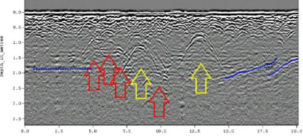
One of the main technical factors that distinguishes GPR from other technologies is the advanced software imaging that is used. As the GPR unit moves along a survey line, it acquires signal traces as the energy is reflected off of successive buried objects. However, due to the size limitations of the GPR antenna, the radiation pattern of GPR antennas is very wide. Therefore, the raw GPR signal does not show the original shape of the objects due to diffraction (Sato 2014). In order to estimate the true profile of the subsurface objects, the GPR signals are processed using software. Subsurface GPR targets are normally stationary, and thus data sets acquired along a survey line can be post-processed for imaging. With advancements in computer processing, software running on a personal computer can process the raw scan data and arrange the signals into a proper diagram. Raw 2D scan images display the targets as an inverted parabola at the object location (see figure 3). These 2D images provide a location for the target, but not the target’s shape or media. With help from high-performance computers, however, the data can easily be converted into a 3D images that show the shape and orientation of the buried object (see figure 4).
Figure 3: Example of a 2D Image Scan from GPR
Figure 4: Example of a computer-generated 3D scan from GPR
With advancements, GPR equipment has become lightweight, durable and portable. However, data collection and survey design methods need to be followed in order to acquire high resolution, subsurface digital data. In Bristow and Jol’s volume of GPR in Sediments, the complexity of GPR is discussed. If the process of data collection is flawed in one of the steps, the data will be corrupt and the collection will need to be repeated. It is Bristow’s opinion that a significant limitation of GPR is the considerable level of expertise necessary to effectively design, conduct, and interpret GPR surveys. Although Bristow’s argument of human error is valid, recently developed GPR models, such as US Radar Inc’s GPRover system, include complete automated systems to mitigate the possibility of human error in the data collection processes.
Although GPR has numerous functions and is frequently used throughout the geotechnical field, the soil type at the site has a direct effect on the depth of the signals, and can be the most significant limitation to GPR performance. Thus, a survey of the site soils should be performed before commencing with a GPR investigation. The depth limitation is most significant with high conductivity materials such as clay, salt contaminated soils, or soils with a high percentage of gravel or rock fragments. Don Kirker of NORCAL Geophysical Consultants explains these types of soils make it extremely difficult for the radar pulses to penetrate, and thus distorts the imaging. More specifically, these soil types can cause the preemptive reflection of electromagnetic waves, directly affecting the depth at which GPR can scan, and is generally a problem that cannot be easily remedied. Kirker recommends acquiring soil samples using borings or test pits to determine if the use of GPR will be efficient. When used in low-density soils, GPR equipment requires movement in order for the radar to examine the specified area as the radar is sensitive to changes in material composition. If GPR is being used to look at a stationary item below grade, there must be enough flat surface for the GPR equipment to be mobilized in order to examine the differences in material composition.
Methodology/Analysis
The majority of this project required qualitative research. The bulk of information was gathered from interviews, Cal Poly Library online journals, and online sources. The three interviews that were conducted during the research were performed over the telephone. The interviewees were selected by the author for their knowledge of their respective fields. Quantitative research that was performed for this paper included statistics on GPR and site logistics. While researching, many journal entries were located that discussed the advantages and disadvantages of GPR which were very valuable.
Interviews
Ross SchofieldWhiting-Turner
The first interviewee was Ross Schofield. Mr. Schofield started work as a Project Engineer for Whiting-Turner in 2013. Since then, Schofield was been promoted to Assistant Project Manager (APM) and was the authors supervisor while an intern for Whiting-Turner. As an APM, Mr. Schofield was responsible for the removal of the ice tank. Schofield supplied the author with the general background specifics of the job site as, valuable details about the ice tank, soil conditions and many site photographs.
Don Kirker
NORCAL Geophysical Consultants
Mr. Kirker has been a Project Manager for 25 years for NORCAL Geophysical Consultants and was recently promoted to Office Manager in 2017. With 25 years of field experience he is currently overseeing all direct activities (administrative and technical) of a geophysical consulting office. Kirker is a specialist in GPR and Geotechnical procedures. Mr. Kirker discussed specifics with the author on GPR including: limitations in the field, different models, applications, and procedures. The author worked with Kirker to create a GPR procedure specialized for Stanford University’s ChEM-H & SNI Building.
Dale Marcum
Cotton Shires & Associates
Mr. Marcum is a part-owner of Cotton Shires & Associates and has 31 years of experience as a Geologic Engineer. Marcum was an valuable source when discussing soil types and outlined the processes followed by a geotechnical engineer when evaluating conditions at various sites.
Proposed GPR Procedure for ChEM-H & SNI Building
Discussions were made with Don Kirker of NORCAL Geophysical Consultants to determine whether a GPR investigation would have been beneficial for the ChEM-H site. Based on these discussions, it appears that the estimated soil conditions (clayey soil with gravels and high groundwater) would have been problematic. In addition, as shown in figure 6, the site received 7.8 inches of rainfall from November 2016-Janurary 2017 (Lawrimore 2017). These soil conditions are a challenge for using GPR techniques. As touched on earlier in the paper, the clayish soil paired with high water content works as a thick membrane that hinders the electromagnetic waves’ ability to penetrate into the earth. In real-world conditions, these circumstances would have likely led to a decision to not use GPR, or, would have prompted more extensive soil testing to distinguish the depth at which GPR could image on this site prior to utilizing this technique.
Assuming further testing revealed that GPR would be viable, the author worked with Mr. Kirker to design a GPR survey. When using GPR on a rectangular area such as the ChEM-H building site, the best practice is set gridlines every 10 feet. As seen in figure 6, the size of the GPR scan for this site is about 300 by 480 feet in size, and the bottom left corner of the site is set as the origin (0,0). The site can then be visualized as a coordinate system with the top right corner being the last coordinate (300,480). Next, the GPR unit is placed at the origin, and the unit’s GPS system is set to these local coordinates. The operator then pushes the GPR unit east along the survey line at a constant slow-walking pace until reaching the edge of the site at point (300,0). The operator then moves 10 feet north to point (10, 480) and walks along the subsequent survey line to the west. This process is repeated until each survey line has been covered. For a survey this size, it was estimated the field work could be completed in one or two days. Perhaps more importantly than the duration of the work, these surveys can typically be performed months prior to the beginning of construction, giving the project team significant lead time to plan for the excavation.
Figure 6: Representation of the survey lines used by GPR on Stanford University’s ChEM-H & SNI Building
Conclusion
GPR is a relatively quick, highly sophisticated subsurface investigative technique that with the advent of powerful personal computers, can provide highly accurate 3-D models of subsurface objects. The technique has been commonly and successfully used for a variety of different applications, including construction environments. However, the technique does have limitations. Water, like clay and other dense materials, creates a condition in the soil that causes the preemptive reflection of electromagnetic waves. Furthermore, a mixture of water and clay form an impenetrable layer for today’s GPR technology, and rocky soils are also problematic. Unfortunately, these limitations describe the estimated soil conditions at the subject site (clay with some gravels and high groundwater). Thus, it is concluded that the use of GPR would likely not have been an efficient technique for this particular site, and the methods that were used (e.g. potholing and test pits) were likely the most appropriate way to investigate for buried objects.
References
Bristow, C. and Jol, H (2003, January 1). GPR in Sediments: Advice on data collection, basic processing and interpretation, a good practice guide. Geological Society, 211, 9-27.
Ennead (2017). Stanford ChEM-H and SNI Building (Chemistry, Engineering & Medicine for Human Health and the Neuroscience Institute) [WWW document]. URL http://www.ennead.com/work/stanford-chem-h-and-sni
Geophysical Survey Systems Incorporated (2018). GPR Products [WWW document]. URL
https://www.geophysical.com/products
Moffat, I. (2018, February 6). How we’re developing underground mapping technologies – lessons from the Beaumont case. The Conversation [WWW document]. URL https://theconversation.com/how-were-developing-underground-mapping-technologies-lessons-from-the-beaumont-case-90687
National Oceanic And Atmospheric Administration (2017). Climate Data Online Search [WWW document]. URL
https://www.ncdc.noaa.gov/cdo-web/search
Obonic (2016, February 13). History of Ground Penetrating Radar Technology [WWW document]. URL
https://www.obonic.de/article/ground-peentrating-radar-history/
Perry, S (2012, November 14). GPR for Pre-Construction – Beyond the Build. Stewart Perry [WWW document] URL https://stewartperry.com/construction-trends/gpr-for-pre-construction/
US Radar Incorporated (2018). Ground Penetrating Radar Products [WWW document]. URL


![3 [2 (6 Bromo 2 phenyl 3H imidazo[4,5 b]pyridin 3 yl)ethyl] 1,3 oxazolidin 2 one](data:image/gif;base64,R0lGODlhAQABAIAAAP///wAAACH5BAEAAAAALAAAAAABAAEAAAICRAEAOw==)