Ammar Khaleel Ibrahim Al-Musawi
School of Engineering
Cardiff University
Wales, United Kingdom
A thesis submitted to the Cardiff University in Candidature for the
degree of Doctor of Philosophy
THE DEVELOPMENT OF NEW ARTIFICIAL INTELLIGENCE
BASED HYBRID TECHNIQUES COMBINING BEES ALGORITHM,DATA MINING AND GENETIC ALGORITHM FOR DETECTION,
CLASSIFICATION AND PREDICTION OF FAULTS IN INDUCTION
Classification and Prediction of Faults in Induction Motors
D
ECLARATION
This work has not been submitted in substance for any other degree or award at this or any other university or place of learning, nor is being submitted concurrently in candidature for any degree or other award.
Ammar Al-Musawi (PhD Candidate) Date:
STATEMENT 1
This thesis is being submitted in partial fulfilment of the requirements for the degree of PhD.
Ammar Al-Musawi (PhD Candidate) Date:
STATEMENT 2
This thesis is the result of my own independent work/investigation, except where otherwise stated, and the thesis has not been edited by a third party beyond what is permitted by Cardiff University’s Policy on the Use of Third Party Editors by Research Degree Students. Other sources are acknowledged by explicit references. The views expressed are my own.
Ammar Al-Musawi (PhD Candidate) Date:
STATEMENT 3
I hereby give consent for my thesis, if accepted, to be available online in the University’s Open Access repository and for inter-library loan, and for the title and summary to be made available to outside organisations.
Classification and Prediction of Faults in Induction Motors
A
CKNOWLEDGMENT
This work was carried out at the School of Engineering, Cardiff University, United Kingdom.
First and foremost, I thank ALLAH for helping me to complete this thesis.
I am grateful to Cardiff University for providing the opportunity and resources required for my study to complete this project. Special thanks for Cardiff University staff especially research office, teaching office, finance office, IT support team, electrical and mechanical workshops.
I would like to express my deepest gratitude to my academic supervisors, Dr. Fatih
Anayi and Dr. Michael Packianather for their excellent guidance during this
research. I am deeply grateful for my external examiner Professor Duc Truong Pham
and internal examiner Dr. Turgut Meydan for their insightful comments and
suggestions for this research.
Of equal importance is my thanks to my small lovely family, my love Rusul El-Dujeili
and gorgeous daughter Fatimah and my little son Ibrahim, I am really grateful for
their supporting and motivating me during my study. My greatest thanks are reserved to my parents, brothers and my grandparents, for their unconditional love, support and encouragement in whole of my life.
Last but not least, I deeply thank the Ministry of Higher Education and Scientific
Classification and Prediction of Faults in Induction Motors
A
BSTRACT
This thesis focuses on applying Artificial Intelligence (AI) methods for detecting, classifying and predicting the faults in induction motors in order to prevent any failures happening during their operation due to loading conditions. It is very important to monitor and detect any faults in the motor during its operation in order to alert the operators so that potential problems could be avoided. In this study, a new AI algorithm has been developed and applied to detect, classify and predict the induction motor faults at an early stage. This is based on a hybrid approach using the Bees Algorithm (BA) and Data Mining called Bee for Mining (B4M), which overcomes the drawbacks of current AI methods in achieving higher classification accuracy with reduced rule set generated from the training data. The proposed B4M algorithm has been implemented, tested and validated using the University of California at Irvine (UCI) dataset, and was compared with other well-known classifiers.
Later, the proposed B4M algorithm was applied in dealing with two most common faults, firstly, that of rotor (one rotor bar, four rotor bars and eight rotor bars), and secondly, bearing defects (inner race, outer race and ball bearing defects). In this research, three condition monitoring techniques involving thermal imaging, current and vibration signal processing have been used to monitor these faults. Further, features such as image metrics and Discrete Wavelet Transform (DWT) coefficients were extracted from the thermal images, and DWT coefficients from the current and vibration signals. Later, five-feature selection methods were applied in order to select the best features for defect classification. Finally, an improvement to the proposed B4M was made by producing a new hybrid classification algorithm by combining
Classification and Prediction of Faults in Induction Motors
Genetic Algorithm (GA) with B4M referred to as GA-B4M where the GA was used for feature selection. The new algorithms were successfully implemented on MATLAB and its performance was tested on real data and compared with other algorithms using the WEKA software.
The results obtained for the thermal image monitoring data showed 98.97% classification accuracy with a reduced rule set containing 10 rules for B4M while a 100% accuracy with a larger rule set of 63 and 72 rules were achieved by Decision Table and OneR classifiers respectively. For the current monitoring data, the classification accuracy fell to 79.62% with only 8 rules for B4M, while 79.20% with 837 rules was achieved by Random Tree. Similarly, for the vibration monitoring data the B4M achieved 80.05% with 7 rules in comparison with Naïve Bayes tree at 79.25% with 31 rules. Furthermore, the results achieved by the proposed hybrid approach GA-B4M on thermal imaging dataset also showed an overall improvement on the classification accuracy reaching 99.85% with 7 rules. Similarly, on the current and vibration dataset the GA-B4M obtained 79.98% with 16 rules and 98.74% with 7 rules respectively. This study has shown that the new proposed classification algorithms B4M and GA-B4M are able to detect, classify and predict the induction motor faults more reliably.
Classification and Prediction of Faults in Induction Motors
L
IST OF
A
BBREVIATIONS AND
N
OMENCLATURES
LIST OF ABBREVIATION
µcAnt-Miner Classification algorithm
2D Two Dimensions
A Approximations coefficients
ABC Artificial Bees Colony
AC Alternative Current
ACO Ant Colony Optimization
AI Artificial Intelligence
ANF Adaptive Neuro-Fuzzy
ANN Artificial Neural Network
AntMinermbc AntMiner multiple-based classifiers
ART-NN Adaptive Resonance Theory Neural Network
ATM Automated Teller Machine
B4M Bee for Mining
BA Bees Algorithm
BEE-Miner Classification algorithm
BEMD Bi-Dimensional Empirical Mode Decomposition
BPNN Back Propagation Neural Network
C_Healthy Healthy current dataset
C4.5 Classification algorithm
C5.0 Classification algorithm
CA Classification Accuracy
cAnt-Miner Classification algorithm
CART Classification And Regression Tree
CFS Correlation based Feature Selection
CN2 Classification algorithm
CT Current Transformer
Classification and Prediction of Faults in Induction Motors
DAG-SVM Directed Analytic Graph Support Vector Machine
DAQ Data Acquisition
db Daubechies (wavelet name)
DBN Deep Belief Network
DC Direct Current
DM Data Mining
DT Decision Tree
DWT Discrete Wavelet Transform
FCFS Fast Correlation-based Feature Selection
FCM Fuzzy C-Mean clustering
FEM Finite Element Model
FFT Fast Fourier Transform
FK-NN Fuzzy K-Nearest Neighbour
FL Fuzzy Logic
FLIR Forward Looking Infrared Radiometer (thermal cameras)
FN False Negative
FP False Positive
FPA Focal Plane Array
Fuzzy-BP Fuzzy Back Propagation
G0 Low pass filter
GA Genetic Algorithm
GDA Generalized Discriminant Analysis
H0 High pass filter
HH High-High HL High-Low HP Horse Power HSB Hue-Saturation-Brightness HSI Hue-Saturation-Intensity HSL Hue-Saturation-Lightness/luminance HSV Hue-Saturation-Value HT Hilbert Transform
Classification and Prediction of Faults in Induction Motors
idwt Inverse Discrete wavelet transform
IEEE The Institute of Electrical and Electronics Engineers
IFO Indirect Field Oriented
IM Induction Motors
IR Infrared
IRT Inferred Thermograph
JPEG, MPEGZ,
PNG Image file extension
Jrip Implantation of “Repeated Incremental Pruning to Produce
Error Reduction (RIPPER)
KNN K-Nearest Neighbours algorithm
LH Low-High
LL Low-Low
LP Logic Programing
LV Laser Vibrometer
MATLAB Matrix Laboratory Software
MBF Markov Blanket Filter
MCSA Motor Current Signature Analysis
MLPNN Multi-Layer Perceptron Neural Network
MMF Magnetic Motive Field
MoASoID Method of Areas Selection of Image Differences
MRA Multiresolution analysis
MRAS Model Reference Adaptive System
MSAF-RATIO15 Method of Selection of Amplitudes of Frequencies-Ratio
15%
NETA InterNational Electrical Testing Association
NI LabVIEW National instruments Laboratory Virtual Instrument
Engineering Workbench software
PART Classification algorithm
PCA Principal Component Analysis
PDT Power Decomposition Technique
Classification and Prediction of Faults in Induction Motors
PPNN Parzen Probabilistic Neural Network
PSD Power Spectral Density
PSNR Peak Signal to Noise Ratio
PSO Particle Swarm Optimization
PSO/ACO A hybrid Particle Swarm Optimisation/Ant Colony
Optimisation algorithm for classification
PSP Problem Solving and Planning
PSVM Proximal Support Vector Machine
PV Prediction Value
PWM Pulse Width Modulation
RBF Radial-Basis Function
REGAL Classification algorithm
RGB Red, Green and Blue
RMS Root Mean Square
ROI Regine of Interest
RPM Rotation Per Minutes
RTD Resistance Temperature Detectors
RVM Relevant vector machine
SBS Sequential Backward Selection
SFBS Sequential Floating Backward Selection
SFFS Sequential Floating Forward Selection
SFS Sequential Forward Selection
SOM Self-Organizing Map
STD Standard Deviation
STFT Short Time Fast Fourier Transform
SURF Speeded-Up Robust Features selection method
SVM Support Vector Machine
SWPT Stationary Wavelet Packet Transform
THI_Healthy Healthy thermal dataset
UCI University of California at Irvine Machine Learning
Classification and Prediction of Faults in Induction Motors
V_Healthy Healthy vibration dataset
VIs Virtual Instrumentation
WEKA Waikato Environment for Knowledge Analysis machine
learning software
WPT Wavelet Pocket Transform
WSN Wireless Sensor Network
WT Wavelet Transform
L
IST OFN
OMENCLATURES Analysing wavelet Angle C Celsius cm Centimetre ∗ Complex conjugate of Edge gradient EfficiencyEMF Electromotive Force Fundamental frequency
Hz Hertz
kW Kilowatt
KNN-based classification error
K Kurtosis
Line frequency Magnetizing current
and Mask direction in image segmentation operators
Mean
MSE Mean Squire Error
MW Megawatt
µm/V Micrometre/voltage
Classification and Prediction of Faults in Induction Motors
mm/s/V Millimetre/second/voltage
and Minimum and maximum values of the attribute, which
represent the range of the feature
NB Naïve Bayes classifier
NN Nearest Neighbour
ngh Neighbourhood size for each selected patch (local search)
e Number of elite bees
nep Number of recruited bees for elite (e) sites
nsp Number of recruited bees for other best (m-e) sites
n Number of scout bees
m Number of selected bees Number of selected features
Number of turns in each phase winding
Ω Ohm
Original feature values Poles number
Rotor speed
Rule coverage percentage Rule fitness value
Scale parameter S Skewness Slip speed Stator frequency Synchronous speed β The coverage-weight
and The derivatives of X and Y points
The gradient
and The height and width of reference image respectively
The image
Classification and Prediction of Faults in Induction Motors
α The quality-weight
x (i,j) The reference image
The row and column coordinates
y (i,j) The threshold image
Time parameter
Total value of the predicted class by the rules
TN True Negative
TP True Positive
, Two different random numbers between 0 and 1
VA Validation Accuracy
V Voltage
Rule fitness value
Classification and Prediction of Faults in Induction Motors
T
ABLE OF
C
ONTENT
DECLARATION ... II
ACKNOWLEDGMENT ... III
ABSTRACT ………..IV
LIST OF ABBREVIATIONS AND NOMENCLATURES ... VI
TABLE OF CONTENT ... XIII
LIST OF TABLES ……… XVIII
LIST OF FIGURES ... XXI
LIST OF PUBLICATIONS ... XXVII
CHAPTER 1:INTRODUCTION AND THESIS OBJECTIVES ... 1
1.1 Introduction ... 2
1.2 Research Aim and Objectives ... 4
1.2.1 Research Objectives ... 4
1.3 Thesis Outline ... 7
CHAPTER 2:INDUCTION MOTORS AND RELATED FAULTS ... 10
2.1 Induction Motor Structure ... 11
2.2 Induction Motor Principle ... 16
2.3 Faults of Induction Motors ... 18
2.3.1 Electrical Faults ... 19
2.3.2 Mechanical Faults ... 24
CHAPTER 3:LITRETURE REVIEW ... 29
Classification and Prediction of Faults in Induction Motors
3.2.1 Thermal Protection based on Traditional Methods ... 32
3.3 Current Monitoring ... 35
3.3.1 Current Protection based on Traditional Methods ... 36
3.4 Vibration Monitoring ... 43
3.4.1 Vibration Protection based on Traditional Methods ... 43
3.5 Artificial Intelligence Techniques for Motor Faults Diagnosis ... 46
3.5.1 Thermal Monitoring based on AI ... 47
3.5.2 Current Monitoring based on AI ... 54
3.5.3 Vibration Monitoring based on AI ... 57
3.6 Common Softwares for IM Fault Detection ... 60
3.7 Data Mining based on Optimization Algorithm for Classification Task ... 61
3.7.1 Optimization Algorithms based on Data Mining for Classification Tasks …..………..……… 62
3.8 Previous Work Observations ... 65
CHAPTER 4:PROPOSED BEE FOR MINING (B4M)………69
4.1 The Bees Algorithm (BA) ... 70
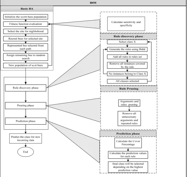
4.2 Proposed Bee for Mining (B4M) ... 71
4.2.1 Data Pre-Processing ... 73
4.2.2 Evaluation Function (fitness function) ... 74
4.2.3 Rule Format ... 75
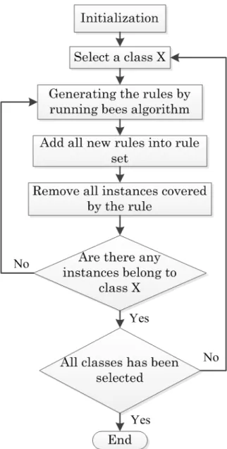
4.2.4 Rule Discovery and Extraction ... 75
4.2.5 Rule Pruning ... 77
4.2.6 Prediction Strategy ... 77
4.3 Testing of B4M Performance on selected UCI Datasets ... 80
4.3.1 Description of Datasets ... 80
4.3.2 The B4M Parameters ... 81
4.3.3 The B4M Test Results ... 82
Classification and Prediction of Faults in Induction Motors
CHAPTER 5: PROPOSED METHODS FOR DATA PRE-PROCESSING AND FEATURE
SELECTION ………...89
5.1 HSV Colour Model ... 90
5.2 Image Segmentation ... 92
5.2.1 Image Segmentation based on Edge Detection ... 93
5.3 Image Metrics ... 99
5.4 Wavelet Transform for Thermal Image, Current and Vibration Signals ... 104
5.4.1 Continuous Wavelet Transform (CWT) ... 107
5.4.2 Discrete Wavelet Transform (DWT) ... 108
5.5 Feature Selection Methods ... 115
5.5.1 Sequential Forward Selection (SFS) ... 117
5.5.2 Sequential Backward Selection (SBS) ... 118
5.5.3 Sequential Floating Selection ... 119
CHAPTER 6: GENETIC ALGORITHM BASED FEATURE SELECTION FOR B4M (GA-B4M) ... 121
6.1 Introduction ... 122
6.2 Genetic Algorithm ... 123
6.3 GA Theoretical Background ... 126
6.4 GA based Feature Selection ... 128
CHAPTER 7:EXPERIMENTAL SETUP AND MEASUREMENTS... 137
7.1 Introduction ... 138
7.2 Condition Monitoring Scheme ... 138
7.3 Test Rig Equipment’s and Data Collection ... 141
7.4 Rig Setup ... 147
Classification and Prediction of Faults in Induction Motors
7.7 Faulty Rotor ... 150
7.7.1 One Bar Rotor Fault ... 151
7.7.2 Four Bars Rotor Fault ... 153
7.7.3 Eight Bars Rotor faults ... 155
7.8 Faulty Bearings ... 158
7.8.1 Outer Race Bearing Fault ... 159
7.8.2 Ball Bearing Fault ... 160
7.8.3 Inner Race Bearing Fault ... 162
CHAPTER 8:DATA AND SIGNAL ANALYSIS ... 165
8.1 Thermal Image Analysis ... 166
8.2 Thermal Image Analysis for Rotor Faults ... 166
8.2.1 Thermal Image Analysis for Four Bars Rotor Fault ... 167
8.2.2 Thermal Image Wavelet Analysis for Rotor Bars Fault ... 176
8.3 Current and Vibration Signals Analysis based on DWT ... 183
8.3.1 Current Signal Analysis ... 186
8.3.2 Vibration Signal Analysis ... 192
CHAPTER 9:RESULTS AND DISCUSSION ………..197
9.1 B4M Classification based on Thermal Image for Fault Detection ... 198
9.1.1 Feature Extraction ... 198
9.1.2 Feature Selection ... 201
9.1.3 Classification Results ... 202
9.1.4 Comparison of B4M Performance with other Classification Algorithms ………..……… 206
9.2 B4M Classification based on Current Signal for Fault Detection ... 210
9.2.1 Feature Extraction ... 210
9.2.2 Feature Selection ... 214
9.2.3 Classification Results ... 215
9.2.4 Comparison of B4M Performance with other Classification Algorithms……….………... 220
Classification and Prediction of Faults in Induction Motors
9.3 B4M Classification based on Vibration Signal for Fault Detection ... 223
9.3.1 Feature Extraction ... 223
9.3.2 Feature Selection ... 226
9.3.3 Classification Results ... 227
9.3.4 Comparison of B4M Performance with other Classification Algorithms……….... 231
9.4 GA-B4M ………233
9.4.1 Classification Results ... 234
9.5 Classification Results for Testing Dataset based on B4M ... 237
9.6 Classification Results for Testing Dataset based on GA-B4M ... 239
CHAPTER 10:CONCLUSIONS AND FUTURE WORK ……….242
10.1 Overview ... 243
10.2 Conclusions ... 244
10.3 Future Work ... 249
REFERENCES ... 251
APPENDIX A-THERMAL IMAGE ANALYSIS ... 271
APPENDIX B-CURRENT AND VIBRATION SIGNALS ANALYSIS ... 280
Classification and Prediction of Faults in Induction Motors
L
IST OF
T
ABLES
C
HAPTER2
Table 2-1: Common faults in induction motors. ... 28
C
HAPTER3
Table 3-1: Sources of abnormal temperature and causes. ... 30Table 3-2: Some previous research experimental setup for induction motor faults detection based on thermography. ... 51
Table 3-3: Common differences between the vibration and current signals. ... 67
C
HAPTER4
Table 4-1: BA parameters. ... 70Table 4-2: classification rule format. ... 75
Table 4-3: Five selected UCI dataset characteristics. ... 81
Table 4-4: B4M parameters. ... 81
Table 4-5: P-value for B4M parameters based on T-test. ... 82
Table 4-6: Classification and Validation Accuracy with 10-fold cross-validation using B4M. ... 84
Table 4-7: Comparison the results of B4M with other classification algorithms. .... 86
C
HAPTER5
Table 5-1: HSV colour space distribution. ... 90Table 5-2: Image neighborhood (center pixel). ... 93
Table 5-3: Masks for direction. ... 94
Table 5-4: Masks for direction. ... 94
Table 5-5: Masks for direction. ... 94
Table 5-6: Masks for direction. ... 94
Table 5-7: Masks for direction in Robert’s operators. ... 95
Classification and Prediction of Faults in Induction Motors
Table 5-10: Masks for direction in LoG. ... 98
Table 5-11: Comparison of the performance of CWT and DWT. ... 111
Table 5-12: Taxonomy of feature selection algorithms. ... 116
C
HAPTER6
Table 6-1: Comparative terminology to human genetics. ... 129Table 6-2: GA parameters values. ... 131
C
HAPTER7
Table 7-1: Current transformer specification. ... 143Table 7-2: Bearing specifications. ... 158
C
HAPTER8
Table 8-1: Frequency levels of wavelet coefficients. ... 186C
HAPTER9
Table 9-1: Sample of thermal image dataset features. ... 199Table 9-2: The selected features for the thermal image dataset. ... 202
Table 9-3: Thermal image dataset description. ... 203
Table 9-4: The proposed B4M classification results. ... 204
Table 9-5: Confusion matrix of the proposed B4M for the thermal image dataset. 205 Table 9-6: Sample of current signal dataset features. ... 212
Table 9-7: The selected features for the current signal dataset. ... 214
Table 9-8: Current signal dataset description. ... 215
Table 9-9: The proposed B4M classification results. ... 216
Table 9-10: Confusion matrix of the proposed B4M for the current signal dataset. ... 218
Table 9-11: Sample of vibration signal dataset features. ... 224
Table 9-12: The selected features for the vibration signal dataset. ... 226
Classification and Prediction of Faults in Induction Motors
Table 9-15: Confusion matrix of the proposed B4M for the vibration signal dataset.
... 229
Table 9-16: The selected features for all the condition monitoring dataset based on
Classification and Prediction of Faults in Induction Motors
L
IST OF
F
IGURES
C
HAPTER2
Figure 2-1: Parts of induction motor [13]. ... 11
Figure 2-2: Induction motor wound rotor [14]. ... 12
Figure 2-3: Induction motor squirrel cage rotor [19]. ... 13
Figure 2-4: Induction motor rotor and stator magnetic circuit [18]. ... 14
Figure 2-5: Block diagram of IM faults [21]. ... 18
Figure 2-6: Probability of fault-occurrence in induction motors [21]. ... 18
Figure 2-7: Squirrel cage of IM broken rotor bar [23]. ... 19
Figure 2-8: Different stator windings faults caused by insulation damage [30]. ... 23
Figure 2-9: Bearing faults [33]. ... 25
Figure 2-10: Different types of IM eccentricity faults [37]. ... 26
Figure 2-11: Misalignment types [38]. ... 26
C
HAPTER3
Figure 3-1: Sample of thermal signature for induction motor (during and after starting)[45]…….………..31Figure 3-2: Flow chart for motor current measurement [37]. ... 36
Figure 3-3: Basic MCSA equipment system [58]. ... 36
Figure 3-4: AI flow chart for IM fault diagnosis [86]. ... 47
C
HAPTER4
Figure 4-1: Basic BA flowchart. ... 71Figure 4-2: Proposed B4M flowchart. ... 73
Figure 4-3: B4M rule discovery flowchart. ... 76
Figure 4-4: Classification procedure of proposed B4M... 79
Figure 4-5: Comparison of classification accuracy (X - different methods; Y - % classification accuracy) achieved by B4M with other methods for five UCI datasets. ... 85
Classification and Prediction of Faults in Induction Motors
Figure 4-7: Compression of average rules number for five UCI datasets. ... 88
C
HAPTER5
Figure 5-1: How to detect the edge by non-maximum suppression. ... 97
Figure 5-2: Thermal image processing diagram. ... 103
Figure 5-3: Wavelet families (a) Harr, (b) Daubechies, (c) Coiflet, (d) Symlet, .... 105
Figure 5-4: DWT decomposition signal to approximation and detail using filters
[181]. ... 109
Figure 5-5: DWT two channel filters [185]. ... 109
Figure 5-6: Filter bank structure of the DWT analysis [185]. ... 110
Figure 5-7: Filter bank structure of the reverse DWT synthesis [185]. ... 110
Figure 5-8: Daubechies wavelet families [189]. ... 112
Figure 5-9: Procedure for thermal image analysis in MATLAB using wavelet toolbox.
... 113
Figure 5-10: Current and vibration signals processing procedure. ... 114
C
HAPTER6
Figure 6-1: Population in GA ... 124
Figure 6-2: Crossover structure... 125
Figure 6-3: Mutation changing. ... 125
Figure 6-4: GA flow chart. ... 126
Figure 6-5: GA based feature selection. ... 130
Figure 6-6: Pseudo code for creation the initial population. ... 131
Figure 6-7: GA fitness function based on the KNN... 133
C
HAPTER7
Figure 7-1: Condition monitoring scheme. ... 139
Figure 7-2: Research framework for motor fault classification. ... 140
Figure 7-3: Induction motor specification. ... 141
Figure 7-4: Dynamometer parts: a- Electric motor dynamometer, b- Dynamometer
Classification and Prediction of Faults in Induction Motors
Figure 7-5: Current transformer setup for collecting the stator current. ... 143
Figure 7-6: National Instrument Data Acquisition card (NI DAQ USB-6211 16 AI
multifunction I/O). ... 144
Figure 7-7: LabView circuit for collecting the stator current data. ... 144
Figure 7-8: Thermal image specifications. ... 145
Figure 7-9: Laser vibrometer: a: Front panel, b: Optical head and c: Oscilloscope.
... 146
Figure 7-10: The experimental test rig. ... 147
Figure 7-11: IM faults scheme. ... 148
Figure 7-12: Healthy conditions. ... 149
Figure 7-13: Thermal image for healthy motor, a: No load, b: 50% load c: 100% load.
... 149
Figure 7-14: The current and vibration signals of healthy IM, a, b, and c represent the
current signals at (a) no load, (b) 50% load and (c) 100% load respectively, while d, e and f represent the vibration signal at different load conditions. ... 150
Figure 7-15: IM circuit diagram... 151
Figure 7-16: One bar fault has been created artificially in the experiment (left figure)
and description of the rotor cage-related faults in circuit diagram (right figure). ... 152
Figure 7-17: Thermal images of one bar rotor fault: a: No load, b: 50% load and c:
100% load. ... 152
Figure 7-18: The current and vibration signals for one bar fault, a, b, and c represent
the three-phase current signal at (a) no load, (b) 50% load and (c) 100% load respectively, while d, e and f represent the vibration signal at different load conditions. ... 153
Figure 7-19: Artificially four bars fault have created in the experiment(left figure) and
description of the rotor cage-related faults in circuit diagram (right figure). ... 154
Figure 7-20: Thermal images of four rotor bars fault: a: No load, b: 50% load and c:
Classification and Prediction of Faults in Induction Motors
Figure 7-21: The current and vibration signals for four bars rotor faults, a, b, and c
represent the three phase current signal at (a) no load, (b) 50% load and (c) 100% load respectively, while d, e and f represent the vibration signal at different load conditions. ... 155
Figure 7-22: IM rotor circuit diagram with eight bars rotor fault and eight rotor bar
faults has been created artificially in the experiment. ... 156
Figure 7-23: Thermal images of eight rotor bars fault: a: No load, b: 50% load and c:
100% load. ... 157
Figure 7-24: The current and vibration signals for eight rotor bars fault, a, b, and c
represent the three-phase current signal at (a) no load, (b) 50% load and (c) 100% load respectively, while d, e and f represent the vibration signal at different load conditions. ... 157
Figure 7-25: Bearing with outer race defect. ... 159
Figure 7-26: Thermal images of outer race bearing defect: a: No load, b: 50% load,
and c: 100% load. ... 159
Figure 7-27: The current and vibration signals for outer race bearing defect, a, b, and
c represent the three phase current signal at (a) no load, (b) 50% load and (c) 100% load respectively, while d, e and f represent the vibration signal at different load conditions. ... 160
Figure 7-28: Bearing with ball defect. ... 161
Figure 7-29: Thermal images of ball bearing defect: a: No load, b: 50% load and c:
100% load. ... 161
Figure 7-30: The current and vibration signals for ball bearing defect, a, b, and c
represent the three-phase current signal at (a) no load, (b) 50% load and (c) 100% load respectively, while d, e and f represent the vibration signal at different load conditions. ... 162
Figure 7-31: Bearing with inner race defect. ... 162
Figure 7-32: Thermal images of inner race defect: a: No load, b: 50% load and c:
100% load. ... 163
Figure 7-33: The current and vibration signals for inner race defect, a, b, and c
Classification and Prediction of Faults in Induction Motors
(c) 100% load respectively, while d, e and f represent the vibration signal at different load conditions. ... 163
C
HAPTER8
Figure 8-1: Thermal image analysis for four bars rotor fault with no load condition a)
original image, b) HSV image, c) Hue image, d) Saturation image, e) Value image, f) Sobel image for Hue, g) Prewitt image for Hue, h) Roberts image for Hue, i) Canny image for Hue, j) LoG image for Hue, k) Otsu image for Hue. ... 169
Figure 8-2: Thermal image analysis for four bars rotor fault with 50% load condition
a) Original image, b) HSV image, c) Hue image, d) Saturation image, e) Value image, f) Sobel image for Hue, g) Prewitt image for Hue, h) Roberts image for Hue, i) canny image for Hue, j) LoG image for Hue, k) Otsu image for Hue. ... 171
Figure 8-3: Thermal image analysis for four bars fault with 100% load condition a)
Original image, b) HSV image, c) Hue image, d) Saturation image, e) Value image, f) Sobel image for Hue, g) Prewitt image for Hue, h) Roberts image for Hue, i) Canny image for Hue, j) LoG image for Hue, k) Otsu image for Hue. ... 173
Figure 8-4: a) The MSE values, and b) The PSNR values for three different load
conditions. ... 174
Figure 8-5: a) The variance value, and b) The mean values for different load
conditions. ... 174
Figure 8-6: a) The thermal image Skew values and b) Thermal image Kurtosis values
for different load conditions. ... 175
Figure 8-7: Thermal image wavelet analysis for four bars rotor fault with no load
condition. ... 177
Figure 8-8: Thermal image wavelet analysis for four bars rotor faults with 50% load
condition. ... 178
Figure 8-9: Thermal image wavelet analysis for four bars rotor faults with 100% load
Classification and Prediction of Faults in Induction Motors
Figure 8-10: Approximation coefficients level (a1) for four bars rotor fault at different
load conditions. ... 180
Figure 8-11: Approximation coefficients level (a2) for four bars rotor fault at different
load conditions. ... 181
Figure 8-12: Approximation coefficients level a3 for four bars rotor fault at different
load conditions. ... 182
Figure 8-13: Wavelet analysis for healthy current signal with three different load
conditions a) No-load, b) 50 % load, c) 100% load. ... 187
Figure 8-14: Wavelet analysis for four bars faulty rotor based on current signal for
with three different load conditions a) No-load, b) 50 % load, c) 100% load. ... 189
Figure 8-15: The d5 and d3 wavelet analysis coefficients for healthy and faulty rotor
based on the current signal with no load condition. ... 190
Figure 8-16: The d5 and d2 wavelet coefficients for healthy and faulty (four bars)
rotor current signal with 50% load condition. ... 191
Figure 8-17: The d5 and d3 wavelet coefficients for healthy and faulty rotor (four
bars) current signal with 100% load condition. ... 191
Figure 8-18: Wavelet analysis for healthy vibration signal of induction motor with
three different load conditions a) No-load, b) 50% load and c) 100% load. ... 193
Figure 8-19: Wavelet analysis for faulty rotor (four bars) vibration signal of with three
different load conditions a) No-load, b) 50% load and c) 100% load.194
Figure 8-20: The d5 and d3 wavelet coefficients for healthy and faulty rotor (four
bars) based on the vibration signal with no-load condition. ... 195
Figure 8-21: The d5 and d2 wavelet coefficients for healthy and faulty rotor (four
bars) based on the vibration signal with 50% load condition. ... 195
Figure 8-22: The d5 and d3 wavelet coefficients for healthy and faulty rotor (four
Classification and Prediction of Faults in Induction Motors
C
HAPTER9
Figure 9-1: The proposed B4M classification accuracy and number of rules based on
thermal image dataset. ... 205
Figure 9-2: Comparison of the classification accuracy for different feature selection
and classification algorithms based on the thermal image dataset. ... 208
Figure 9-3: Comparison of the number of rules for different feature selection and
classification algorithms based on the thermal image dataset... 209
Figure 9-4: Comparison of the classification accuracy for different feature selection
and classification algorithms based on current signal dataset. ... 221
Figure 9-5: Comparison of the number of rules for different feature selection and
classification algorithms based on current signal dataset. ... 222
Figure 9-6: Comparison of the classification accuracy for different feature selection
and classification algorithms based on the vibration signal dataset. ... 232
Figure 9-7: Comparison of the number of rules for different feature selection and
classification methods based on the vibration signal dataset. ... 233
Figure 9-8: The comparison of classification and number of rules for different
classification methods based on the thermal image dataset. ... 235
Figure 9-9: The comparison of classification accuracy and number of rules for
different classification methods based on the current signal dataset. ... 236
Figure 9-10: The comparison of classification accuracy and number of rules for
different classification algorithms based on the vibration signal dataset. ... 236
Figure 9-11: Classification accuracy for test dataset of thermal image. ... 238
Figure 9-12: Classification accuracy for test dataset of current signal. ... 238
Figure 9-13: Classification accuracy for test dataset of vibration signal. ... 239
Figure 9-14: Classification accuracy of thermal image test dataset based on GA-B4M.
... 240
Figure 9-15: Classification accuracy of current test dataset based on GA-B4M. ... 241
Classification and Prediction of Faults in Induction Motors
L
IST OF
P
UBLICATIONS
[1] M. S. Packianather, A. K. Al-Musawi, and F. Anayi, “Bee for mining (B4M) – A novel rule discovery method using the Bees algorithm with quality-weight and coverage-weight,” Proc. Inst. Mech. Eng., 2019.
[2] A. K. Al-Musawi, F. Anayi, and M. S. Packianather, ”Three-Phase Induction Motor Faults Detection based on Thermal Image Segmentation” has been submitted to the Infrared Physics and Technology.
1
CHAPTER
1
I
NTRODUCTION AND
T
HESIS
O
BJECTIVES
“This chapter describes the main purposes of maintenance strategies. It also introduces condition monitoring and describes the different types of condition monitoring systems and techniques. Finally, the research aim, objectives and the thesis structure have been presented”.
1.1 Introduction
The induction machine condition monitoring plays a vital role in the industrial facilities as it guarantees both the reliability and low cost operation [1]. Condition monitoring gives an opportunity to maintain the machine at early stage or before any possible disastrous accident or any dangerous damage. Furthermore, it allows having a schedule or planned service for the technician, which will decrease the possibility of production losses. Induction motors (IM) have been widely used in most of industrial applications due to their robustness, low cost and operation (operate with an easily available power supply). However, IM may fail far sooner than its designed lifetime because of the installation issues, duties, and operational environments. Recently, the approach of “run-to-fail” has been rejected for most manufacturing process and operations. For that reason, the condition monitoring has been required as an alternative system to protect the motor based on the motor data collection and analysis during its operation, which makes it acceptable and more desirable due to its capability of detecting the motor faults in early stage [2]. Moreover, most of the companies and industries are searching/looking for the best condition monitoring methods in order to reduce the damage to the environments or the maintenance cost, which may mitigate any possible injuries to the operators or technicians. There are three essential maintenance strategies as follows [3], [4]:
a) Preventive maintenance (time-based-maintenance): the machine are
thoroughly inspected and tested at a set of intervals, and any necessary maintenance has to be carried out to remedy faults present within the system.
b) Breakdown maintenance: the machines are run until they completely fail, this kind of maintenance it considered as a very expensive in terms of machine damage and lost output, or it may also lead to dangerous occurrences.
c) Predictive maintenance: this strategy requires a continuous monitoring in
order to detect and diagnose any defects happened to the machine. If the defects have been detected, the maintenance must be planned and executed as soon as possible.
The main objectives of these maintenance are assisting the machine for productivity improvements, extend the machine life, minimise the number of maintenance and replacements routine and producing a high quality products [1], [5]. In the induction motors, faults could be occur in the rotor, bearing, stator or any other peripheral devices that are connected to the induction motor. These faults have been broadly classified into broken rotor bars, bearing faults, eccentricity, gearbox failure and many others. In other word, the mentioned faults may produce one or more symptoms such as unbalanced line current and voltages, excessive heating, torque pulsations, vibration and noise and other symptoms.
The recent development in the computer software and electrical equipment based on the Artificial Intelligence (AI) systems (machine learning) attract the attention of the electrical engineers to lunch an extensive researches to apply the AI techniques for motor fault detection and diagnosis [6]. The AI techniques such as Artificial Neural Network (ANN), Fuzzy Logic (FL), Genetic Algorithm (GA) and many others have been applied to induction motor faults detection and diagnosis. These techniques have used association, reasoning and decision-making process as would the human brain in
1.2 Research Aim and Objectives
The aim of this research is to investigate and recommend a new condition monitoring technique based on three common approaches, which are thermal image, motor current signal analysis and vibration signal analysis. The thermal image has been captured using FILR thermal camera, the motor current signals have been collected using current transformers and the vibration signals have been collected using laser vibrometer.
Specifically, the aim of this research is:
To develop and improve a new artificial intelligence technique based on Bees Algorithm (optimization algorithm), data mining and Genetic Algorithm to be used for detecting, classifying and predicting the motor faults at an early stage.
1.2.1 Research Objectives
In the last decades, there has been a huge amount of research into creating a new condition monitoring technique for electrical machines based on AI [8]–[10]. The research and development of designing a newer and alternative diagnostic system is continuous. However, since condition monitoring and fault diagnosis system should always suite new, the condition monitoring based on the AI has been developed rapidly to cover all the induction motor situations under any circumstances. This continuous development and research have argued by the fact that there is no specific system/technique could be considered generally or the best for all existing applications, since an operator must treat each motor drive as a unique entity. In this respect, the fundamental causes, mechanical load characteristics, potential failure
modes and operational conditions have to be carefully taken into consideration when designing a monitoring system for specific applications [11].
Additionally, all previous studies that are carried out in the field of condition monitoring show that there have been many challenges and opportunities for engineers and researchers to focus on. Several solutions and recommendations concerning the condition monitoring methods have been given in this area, generally depending on the machine type, operating conditions (loading), size, cost constraints, available instruments etc. Besides, several fields of technology and science such as thermal, electrical, mechanical and sometime chemical engineering should be considered and combined whenever possible, in order to allow analysts to correlate different aspects of each technology to troubleshoot symptoms and determine a course of action to avert failures. This is also a stringent requirement when aiming to build or design a competitive condition monitoring system.
In this research, three computational tools would be extensively used. These are NI LabVIEW, MATLAB and WEKA software’s. NI LabVIEW is systems engineering software for applications that require test, measurements and control with rapid access to hardware and data insight. MATLAB is a very ubiquitous scientific and technical computing tool that has found wide applicability. WEKA is a machine learning environment created by University of Waikato. This research was oriented to achieve the following objectives:
In terms of machine learning
1- To develop a new innovative, non-intrusive, accurate, reliable and simple artificial intelligence technique based on Bees Algorithm (optimization
algorithm) and data mining approach, called Bee for Mining (B4M) that is able to detect and diagnose the motor faults in an early stage.
2- To validate the new proposed classification algorithm based on the University of California at Irvine Machine Learning Repository (UCI machine learning datasets).
3- To compare the capability of the new algorithm with other well-known classification algorithms based on the UCI machine-learning datasets.
In terms of condition monitoring
1- To explore induction motor failures modes and understand condition-monitoring techniques.
2- To design and construct a test rig with the associated instrumentation for induction motor faults to collect the real data from the induction motor with seven faulty cases and three different condition monitoring technique, thermal image, motor current signature analysis and vibration signal.
3- Apply different feature extraction and feature selection methods with purpose of extracting and selecting the best fault information from the raw images and signals for all three condition-monitoring techniques.
4- To apply the new proposed classification algorithm that are relaying on the Bees Algorithm and Data Mining approaches (B4M) in the suggested condition monitoring techniques.
5- To compare the capability of the new algorithm with other well-known classification algorithms based on the thermal image, current and vibration signals.
In terms of the machine learning hybrid system
1- To build a new hybrid classification system based on the Genetic Algorithm and the proposed classification algorithm (B4M), which is called (GA-B4M), in order to make the classification system more robust and accurate for classifying the motor faults correctly.
2- To apply the new hybrid system to the seven faulty cases and three suggested condition-monitoring techniques.
1.3 Thesis Outline
Chapter 1: Introduction and Thesis Objectives. It presents the research
objectives and the thesis outline.
Chapter 2: Induction Motors and Related Faults. Since the induction motor
is aimed to study in this research, this chapter introduces background information about the induction motor such as induction motor structure and principle. It also introduces the most common types of electrical and mechanical faults, because they are the problems that are aimed to be solved.
Chapter 3: Literature Review. The previous related work on condition
Chapter 4: Proposed Bee for Mining (B4M). In this chapter, the combination of the Bees Algorithm and Data Mining have been described in detail in order to produce the proposed Bee for Mining (B4M).
Chapter 5: Proposed Methods for Data Pre-Processing and Feature
Selection. In this chapter, the proposed methods for pre-processing the
induction motor dataset have been explained for all condition monitoring approach, thermal image, current and vibration signals.
Chapter 6: Genetic Algorithm based Feature Selection for B4M
(GA-B4M). This chapter explains how the Genetic Algorithm has been used as
feature selection method and how it works theoretically.
Chapter 7: Experimental Setup and Measurements. The practical work of
this research starts in this chapter. It shows what equipment was used in experiments, how the induction motor test rig was built, and the procedure of the experiments, how the required measurements were taken and how the acquired data were stored in order to be proceeded in the next chapter. It also shows the induction motor healthy and the faulty signals and how the faults have been generated.
Chapter 8: Data and Signal Analysis. It explains how to analyse the motor
data and signals based on the proposed methods that are explained in previous chapters. It also shows the signal analysis for all three condition monitoring approaches (thermal image, current and vibration condition monitoring).
and WEKA software’s. Then, the results of the other classification algorithms have been discussed and compared with the proposed technique.
Chapter 10: Conclusions and Future Work. All the discussions about the
results of testing the proposed techniques in both simulation and practical work are concluded in this chapter. It also introduces some recommendations for future work.
2
CHAPTER
2
I
NDUCTION
M
OTORS AND
R
ELATED
F
AULTS
“In this chapter, the concept of induction motor and a brief review of what are the main types of induction machine faults are presented. In order to cover the understanding of the induction motors, the induction motor structure and its fundamental are introduced first. Then brief review of induction motors symptoms and mechanisms of the electrical and mechanical faults are presented”.
2.1 Induction Motor Structure
Induction Motors are also known as asynchronous motors and are typically Alternative
Current (AC) electric motors. In induction motors, electric current is required to
generate the torque to drive the motor [12]. It has been considered as asynchronous machine since they operate at speed lower than the synchronous speed. Worth noting, asynchronous speed is the speed of rotating magnetic field, which depends upon the machine pole numbers and the supplied frequency. The driving torque is achieved by electromagnetic induction that is obtained from the electromagnetic field of the stator coils. IM contains magnetic circuits, which are connected to two electric circuit, these circuits are:
a) Magnetic circuit, which is responsible for carrying the magnetic flux that is made of laminated magnetic material generally steel.
b) Electrical circuit, which is normally made of insulated aluminium or copper to carry the current.
These two circuits are very important for rotating the main part of the induction motor, which is rotating part (rotor) as illustrated in figure 2-1.
A series of thin aluminium pieces permanently attached to a laminated cylinder make up the rotor structure. The rotor pieces are attached in a horizontal fashion and parallel to the rotor shaft. Towards the edge of the rotor, aluminium plates are intertwined with a shorting ring. There are two types of rotor: wound and squirrel cage rotors. The wound rotor of an induction motor is similar to a three-phase stator winding because it carries a poly-phase winding. In addition, three isolated slip rings are connected to a rotor winding which are mounted on rotor shaft. In this type of rotor (wound rotor) as shown in figure 2-2, an external changeable resistance is connected to the slip rings in order to limit the rotor heating and starting current.
Figure 2-2: Induction motor wound rotor [14].
During starting up, the inserted resistance to the wound rotor produces less starting current with high starting torque than the squirrel cage rotor [13]. So far, wound rotor has been concerned; the structure and functions of squirrel cage rotor will be explained. It consists of parallel slots with a laminated cylinder core in order to carry rotor conductor, no wires are connected but it has a thick bars of aluminium or copper. Furthermore, it has two end rings that are braced or welded, and these ends are short circuit. For that reason, it is impossible to connect or add any external variable resistance. The shaft is usually not parallel to the rotor bars, it is a little bit skewed, as shown in figure 2-3.
Figure 2-3: Induction motor squirrel cage rotor [19].
The squirrel cage rotor is different from the wound rotor in a number of aspects. The main difference is that the squirrel cage rotor is economical, simpler and more rugged than the wound rotor. Additionally, if a constant frequency and constant voltage connected to the squirrel cage rotor, it produces a constant speed. Thus, it is compatible with stationary speed drive system [13][14]. Otherwise, many industries required adjustable speed or various speed for products applications. In addition, it is important to ask why squirrel cage induction motors are preferred in most industries than DC motors.
In terms of Direct Current (DC) motor has been used in order to obtain adjustable range of speeds. Nevertheless, because of the DC motors are very expensive and the brushes and commutators need to be serviced frequently, the squirrel cage induction motors are preferred in most industries because as mentioned above, rugged, cheap and no need for commutators. Recently, the squirrel cage motors are used in high and low-performance applications owing to its versatility.
Whenever a current and high potential is applied to the stationary runs/coils, a strong magnetic field is induced in the stator coils [15]. The stator windings are arranged in a pattern that the magnetic field appears to synchronously rotate around the motor housing [16]. Through the electromagnetic induction, the power will transfer from one part to other. When stator windings are powered from a three-phase AC source, a rotating magnetic field is induced, then it converts electrical energy into mechanical energy [17].
Figure 2-4: Induction motor rotor and stator magnetic circuit [18].
Induction motors operate under a complex system of current, voltage and magnetic field in a synchronized manner to induce the rotary effect. For the case of three-phase AC induction motors, however, no excitation is required for it to start. Instead, the motor is a self-starting device [15]. In between the rotor and stator, an air gap/space allows free movement for the rotor during its operation [18] as illustrated in figure 2-4 above. In effect, a synchronous speed is established in the stator. An electromotive force (EMF) is induced in the rotor bars by the magnetic field produced in the stator windings. Afterwards, a current is generated in the rotor and a separate magnetic field
windings. This current is created due to the relative speed between rotor conductor and the rotating flux. Consequently, a magnetic flux generate a force that pulls the field in the rotor, thereby inducing a turning effect on the rotor. As described in Lenz’s Law, the rotor spins in a similar direction in order to reduce the causing effect that is the relative speed. The resultant rotation is in accordance with Faraday’s law of electromagnetic induction “EMF is induced in a circuit due to changing magnetic flux linkage experienced within the circuitry.”
In addition to the above two main parts of induction motor, there are other parts which are:
a) Bearings: two bearings have been used for supporting the rotor at each end in
order to rotate the shaft.
b) End flanges: two flanges are placed in both ends of induction motor for
supporting the bearings, and
c) Shaft: is used for transmitting the generated torque to load.
Another significant aspect on induction motors is that these motors are generally suitable for continuous speed operations. Furthermore, compared to other alternatives, induction motors are cheaper to acquire and maintain. While designing induction motor, operational features can be examined using several calculations described in the subsequent subsections. By applying these calculations, an electrical engineer will be in a position to select a motor that best suits a particular job. The section below describes briefly the IM principles.
2.2 Induction Motor Principle
The magnetic field distribution between the air gap and the rotation is one of the most fundamental concept. Because of non-ideal winding distribution, the effect of the space harmonic and slots have been neglected. The sinusoidal current in the three-phase induction machine is impressed on the stator winding, as it is given below [19]:
cos
cos 120° (2-1)
cos 120°
Where: : maximum current, : line frequency.
In order to produce Magnetic Motive Field (MMF) wave and distribute it sinusoidally, each phase will work individually to produce the MMF, which pulses about the X-axis and Y-axis. The expressions of instantaneous MMF at spatial angle ( ) are given below [19]:
cos
cos (2-2)
cos
Where: : number of turns in each phase winding, : spatial angle.
The MMF are:
cos cos cos (2-3) The MMF has been distributed sinusoidally, which rotates the air gap at frequency ( ). Furthermore, for two poles induction motors the current variation has one
revolution per cycle, which is created by , . Thus, the rotational speed for P-pole motor can be as given below:
, (2-4)
Where: : synchronous speed (RPM), : stator frequency (Hz), : number of pole pairs.
The motor synchronous speed indicates the speed of rotation for stator magnetic field. is a function of pole number and the frequency of the power source in the motor as explained above in the equation (2-4). The rotor conductors are subjected to rotating magnetic field when the induction motor rotor is stationary and inducing the short circuit rotor current to rotate at the same rotor frequency. Hence, the interactions between the rotor MMF and the air gap flux will produce the torque. The difference between the rotor speed and synchronous (stator) field speed gives the slip speed. The slip speed of an induction motor is calculated and expressed as a fraction of the synchronous speed. Slip speed is an important parameter in the motor because without slip, the induction motor will produce a torque equivalent to zero. The motor slip equation is expressed as follows:
(2-5)
Where: : slip, : rotor speed (RPM).
Furthermore, the motor efficiency should also be considered. This is determined by comparing the input and output power. Higher efficiency is desired in induction motors since they are used for energy conversion. Low values of efficiency implies that the motor is less productive and it should be substituted.
100% (2-6)
2.3 Faults of Induction Motors
Induction motors are reliable electric machines [9]. However, they are susceptible to several electrical and mechanical faults as shown in figure 2-5. Flaws in induction motor often lead to unbalanced stator current and voltages [20], reduction in efficiencies, torque oscillations, excessive vibrations, overheating and torque reduction.
Figure 2-5: Block diagram of IM faults [21].
As illustrated in figure 2-6 [21], faults in induction motor occur in varied magnitudes with bearing faults assuming higher probabilities of occurrence followed by stator faults, but rotor faults assume the least probability of occurrence but it still need to monitored due to the environment change.
10% 12% 38% 40% Rotor fault Miscellaneous faults Stator winding faults Bearing faults
The most common electrical and mechanical faults of the induction motors will be explained below.
2.3.1 Electrical Faults
Electrical faults in an IM can stem from rotor bars and stator faults, which are briefly explained below.
2.3.1.1 Rotor Faults
Figure 2-7 shows a squirrel cage for an AC induction motor that comprises of end rings and rotor bars. A broken bar can be completely or partially cracked. Such bars are susceptible to breaking due to constant starts at rated voltages, manufacturing defects, mechanical stresses or thermal stresses caused by metal fatigue [22].
Figure 2-7: Squirrel cage of IM broken rotor bar [23].
Many reasons of causing broken rotor bar, due to manufacturing fault, such as irregular metallurgical stress might happen during brazing processes, which sometimes lead to rotor rotation failure, and an extra stress on the rotor bars due to large centrifugal force, which caused by heavy end ring. These faults have also effect on the rotor currents
different locations of the rotor such as at the joint between end ring and bars. A.
Bonnet and G. Soukup [25] stated that the most rotor faults are happened at the joint
between the end ring and bars due to manufacturing fault or any other possibilities, for instance if the motor is subject to stop and start frequently or long time to start up. Recently, broken rotor bars are common faults in induction motors. Furthermore, the main reasons that causes the faults in induction motors rotors are described below [26]:
a) Manufacturing defects as mentioned earlier in the last section.
b) Thermal stress, which is caused by the hot spot, sparking, excessive losses or thermal overload.
c) Mechanical stress due to bearing failure, fatigued parts and lose lamination.
d) Magnetic stress due to unbalance magnetic pull, vibration, electromagnetic force and electromagnetic noise.
e) Dynamic stress due to cyclic stress, shaft torques and centrifugal forces.
f) Environmental stress due to moisture and chemical into the rotor material.
A broken bar in an induction motor induces a series of side effects. One of the commonly known effect is the appearance of sideband components. The so-called sidebands are observed in the power continuum of the stator current towards the right edges and left sides of the fundamental frequency. The lower side band element is triggered by magnetic and electrical asymmetries of the rotor cage within AC asynchronous motors. Consequently, constant speed ripples produced by the resulting force pulsations instigate the right side band element. These side band frequencies are
determined by classical twice slip frequency sidebands, therefore occur at ± 2s around the supply frequency as follows [27]:
1 (2-7)
Where : fundamental frequency, = 1, 5, 7, 11, 13… due to normal configuration
of winding, s: slip per unit.
Sideband elements, as explained earlier, are widely used for reorganization/correction of induction motor faults. Other electric properties created by the broken bars including stator current envelopes, oscillations speed, instantaneous power oscillations and torque ripples have been used for motor fault detection [28].
The previous section has explained the squirrel cage rotor faults in induction motors. Turning now to wound rotor faults, rotor windings of wound rotor are linked to external resistance via slip rings. By adjusting the resistance, it is possible to control the torque/speed properties of the induction motor. Further, it is possible to start the motor with low in-rush current through insertion of high- resistance windings in the rotor circuit. However, as the motor accelerates towards higher speed, the resistance of winding decreases, which is leading to faults. In addition, slip rings that are used in wound rotor motors are susceptible to damage. Subsequently, current in the rotor windings drops below the expected values [29]. Just like stator windings, rotor windings are also susceptible to failure due to a number of catastrophe issues such as:
a) Insulation faults due to motor breakdown.
b) Overheating which is caused by an electrical overload, leading to power-surge within the rotor coils or unbalanced motor supply voltage, and open-rotor bars
c) Rotor locks emanating from mechanical faults can generate current that exceeds the starting current. However, rotor overheating may increase rotor losses. At a heightened levels, the motor temperatures may increase up to 350 °C.
2.3.1.2 Stator Faults
Stator faults are caused by one of the following factors, which create short-circuiting and effects on the stator coils:
a) Mechanical forces and stresses.
b) Thermal stresses and normal ageing process.
c) Environmental pollution.
d) Switching transient and electrical overloads.
Short-circuiting in stator windings is common feature in induction motors. It occurs between turns of two phases, or between turns of a single phase, or between turns of all phases. In addition, short-circuiting is observed between the stator core and windings of the conductor. The following section summarizes the faults in stator windings:
Short circuiting effects between turns of a similar phase as illustrated in figure 2-8a below. Winding short circuits are illustrated in figure 2-8b. Figure 2-8c and figure 2-8d illustrate short-circuiting between stator core and windings respectively. Similarly, figure 2-8e captures short-circuiting throughout the connections, while figure 2-8f illustrates short-circuiting between two phases due to abrasion and stator voltage
transients [30]. Over-rated and sub-rated voltage supplies could also create these faults [31].
Figure 2-8: Different stator windings faults caused by insulation damage [30]. The stator faults could also be effected by an external faults as described briefly below:
a) Single-Phase Faults
The induction motors are subjected to loss one of their phases and this issue will have an effect on the power system distribution. This kind of fault causes a serious problem, because it prevents the motor to operate in actual horsepower. Furthermore, to detect the single-phase fault, for some cases the negative phase current has been used during the motor operation. Thus, the motor voltage and
current measurement was used for detecting the phase fault before loading the motor.
b) Phase Unbalance Faults
The probability of the unbalance faults is less than full phase faults, but if it happened, it may have similar consequences. Recently, more attention has been paid for the new induction motor installation in order to distribute the balance equally.
Having discussed the electrical faults and their causes, the final section of this chapter addresses the most common mechanical faults in induction motors.
2.3.2 Mechanical Faults
Mechanical faults can be caused by either of the following faults: bearing faults, eccentricity and misalignment. These faults account for 40% to 50% of the total faults observed in the motor [32].
2.3.2.1 Bearing Faults
Bearing faults are complications encountered in either the rolling element or the ball bearings that touch the inner and outer rings [9]. Ball bearings or the rolling elements continuously rotate in tracks inside the bearing ring. Bearing fault defects on outer ring, ball or inner ring. These faults could occur by internal stresses, vibrations, currents and inherent eccentricity that influence the formation of mechanical faults. A clear analysis of motor history helps to arrive at a conclusive statement that motors were previously driven by variable frequency drives lead to exhibited several premature failures. Misalignment faults and bearing faults within the load drive system
may generate periodic variations to motor. Figure 2-9 illustrates four types of rolling bearing misalignments [33].
Figure 2-9: Bearing faults [33].
2.3.2.2 Eccentricity Faults
Eccentricity fault is also known as air gap eccentricity, which occurs in two primary forms namely, dynamic and static forms [34]. In static eccentricity fault, rotation of the axis is displaced from the centre with the position of the least air gap length being fixed in space. The fault occurs due to inaccurate positioning of the stator or/and rotor during the construction phase [35]. The displacement of the rotor from the central axis within the stator bar makes the distribution field in the air gap to be asymmetrical. As a result, a non-uniform air gap is created, thus generating a radial force of the electromagnetic origin. The effect is commonly termed as “Unbalanced Magnetic Pull” (UMP) which works towards the minimum air gap.
![Figure 2-2: Induction motor wound rotor [14].](https://thumb-us.123doks.com/thumbv2/123dok_us/11080173.2994454/40.892.255.700.499.715/figure-induction-motor-wound-rotor.webp)
![Figure 2-3: Induction motor squirrel cage rotor [19].](https://thumb-us.123doks.com/thumbv2/123dok_us/11080173.2994454/41.892.293.662.107.382/figure-induction-motor-squirrel-cage-rotor.webp)
![Figure 2-4: Induction motor rotor and stator magnetic circuit [18].](https://thumb-us.123doks.com/thumbv2/123dok_us/11080173.2994454/42.892.231.727.413.737/figure-induction-motor-rotor-stator-magnetic-circuit.webp)
![Figure 2-8: Different stator windings faults caused by insulation damage [30].](https://thumb-us.123doks.com/thumbv2/123dok_us/11080173.2994454/51.892.169.788.209.732/figure-different-stator-windings-faults-caused-insulation-damage.webp)
![Figure 2-10: Different types of IM eccentricity faults [37].](https://thumb-us.123doks.com/thumbv2/123dok_us/11080173.2994454/54.892.290.664.416.742/figure-different-types-im-eccentricity-faults.webp)

![Figure 3-3: Basic MCSA equipment system [58].](https://thumb-us.123doks.com/thumbv2/123dok_us/11080173.2994454/64.892.247.706.828.1076/figure-basic-mcsa-equipment-system.webp)
![Figure 3-4: AI flow chart for IM fault diagnosis [86].](https://thumb-us.123doks.com/thumbv2/123dok_us/11080173.2994454/75.892.346.612.113.460/figure-ai-flow-chart-for-im-fault-diagnosis.webp)