1
1 September 2015 Version 7.0Guidelines for reporting well data to
authorities after completion
2
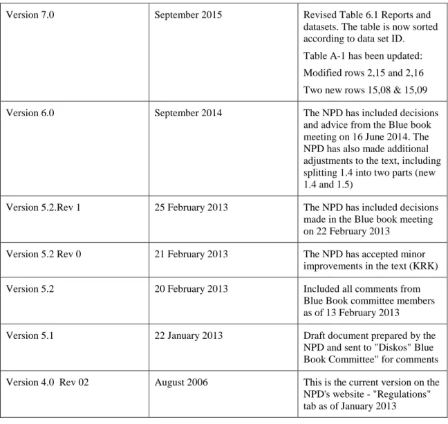
Revision control matrix:
Version 7.0 September 2015 Revised Table 6.1 Reports and datasets. The table is now sorted according to data set ID. Table A-1 has been updated: Modified rows 2,15 and 2,16 Two new rows 15,08 & 15,09 Version 6.0 September 2014 The NPD has included decisions
and advice from the Blue book meeting on 16 June 2014. The NPD has also made additional adjustments to the text, including splitting 1.4 into two parts (new 1.4 and 1.5)
Version 5.2.Rev 1 25 February 2013 The NPD has included decisions made in the Blue book meeting on 22 February 2013
Version 5.2 Rev 0 21 February 2013 The NPD has accepted minor improvements in the text (KRK) Version 5.2 20 February 2013 Included all comments from
Blue Book committee members as of 13 February 2013
Version 5.1 22 January 2013 Draft document prepared by the NPD and sent to "Diskos" Blue Book Committee" for comments Version 4.0 Rev 02 August 2006 This is the current version on the NPD's website - "Regulations" tab as of January 2013
3
REPORTING REQUIREMENTS FOR DIGITAL WELL DATA
(Drilling Regulations, Section 12)
CONTENTS
CONTENTS ... 3
1.
INTRODUCTION ... 7
1.1.
OBJECTIVES ... 7
1.2.
REGULATORY REQUIREMENTS REGARDING DELIVERY ... 7
1.3.
REPORTING GUIDELINE PRINCIPLES ... 8
1.4.
GENERAL REQUIREMENTS FOR ALL REPORTING ... 8
1.5.
GUIDELINES FOR ALL REPORTING TO DISKOS ... 9
1.6.
LOGDATA CURVE SPECIFIC REQUIREMENTS ... 10
2.
RAW DATA ... 11
2.1.
WELL-LOG DATA ... 11
2.1.1.
Content ... 11
2.1.2.
Quality... 11
2.1.3.
Format and Structure... 11
2.2.
CORE DATA ... 12
2.2.1.
Quality... 12
2.2.2.
Content ... 12
2.2.3.
Format and Structure... 12
2.3.
GEOCHEMICAL DATA ... 12
2.3.1.
Quality... 12
2.3.2.
Format and Structure... 13
2.4.
WELLBORE SEISMIC DATA ... 13
2.4.1.
VSP ... 13
2.4.2.
Check shot ... 13
2.4.3.
Structure ... 13
2.5.
MUDLOG DATA ... 13
2.5.1.
Content and Quality ... 13
2.5.2.
Structure ... 13
2.6.
WELLPATH DATA ... 13
4
2.6.2.
Structure ... 14
3.
EDITED RAW DATA ... 14
3.1.
WELL COMPOSITE LOG ... 14
3.1.1.
Definition ... 14
3.1.2.
Purpose ... 14
3.1.3.
Quality... 15
3.1.4.
Content ... 15
3.1.5.
Guidelines for Compositing ... 15
3.1.6.
Format and Structure... 16
3.2.
ADDITIONAL COMPOSITED DATA (PETROPHYSICAL COMPOSITE) . 16
3.2.1.
Purpose ... 16
3.2.2.
Quality... 16
3.2.3.
Content ... 16
3.2.4.
Format and Structure... 16
4.
INTERPRETED DATA... 16
4.1.
PETROPHYSICAL INTERPRETATIONS ... 16
4.1.1.
Purpose ... 16
4.1.2.
Quality... 17
4.1.3.
Content ... 17
4.1.4.
Format and Structure... 17
4.2.
WELLPATH (or WELLTRACK) DATA... 17
4.2.1.
Purpose ... 17
4.2.2.
Quality... 17
4.2.3.
Content ... 18
4.2.4.
Format and Structure... 18
4.3.
CORE DATA ... 18
4.3.1.
Purpose ... 18
4.3.2.
Content ... 18
4.3.3.
Format and Structure... 18
4.4.
PROCESSED WELLBORE SEISMIC DATA... 18
4.4.1.
VSP ... 19
4.4.2 TIME-DEPTH-VELOCITY (TDV) DATA ... 19
4.5.
FORMATION PRESSURE DATA ... 19
4.5.1.
Purpose ... 20
5
4.5.3.
Format and Structure... 20
5.0
DIGITAL IMAGES OF INTERPRETATION LOGS ... 20
5.1
Purpose ... 20
5.2.1
Content and Format ... 21
6.
REPORTS AND DATASETS ... 21
APPENDIX A Diskos File Naming Convention and File Structure for Well Data Files24
1.0
Purpose ... 24
2.0
Conventions ... 24
3.0
File Name Structure ... 24
APPENDIX B Content Information for Specific Data Sets ... 25
1.0
Purpose ... 25
2.0
Layout... 25
3.0
RAW DATA ... 25
3.1
WELL-LOG DATA ... 25
3.1.1
Header data ... 25
3.1.2
Other Key Attributes ... 25
3.1.3
Logging Summary Document ... 27
3.2
CORE DATA ... 27
3.3
MUDLOG DATA ... 29
3.3.1
Curve Types ... 29
3.3.2
Lithology Coding ... 31
3.4
WELLPATH DATA ... 33
3.4.1
Raw and Computed Wellpath Data... 33
3.5
COMPOSITE WELL LOGS ... 34
4.1
COMPUTED WELL LOG DATA ... 35
4.2
TIME-DEPTH-VELOCITY DATA ... 36
4.3
FORMATION PRESSURE DATA ... 37
APPENDIX C Data Formats for Text Data and Documents ... 39
APPENDIX D Definitions ... 40
APPENDIX E Well-log Compositing Procedures ... 41
PROCESSING REQUIREMENT ... 41
1.0
RAW LOGS ... 41
1.1
General Specifications ... 41
1.2
Data verification ... 41
6
2.
COMPOSITE LOG ... 42
2.1
General specifications ... 42
2.2
Data editing... 42
2.3
Depth Shifting... 43
2.4
Tie-ins and merging ... 44
7
1.
INTRODUCTION
This document explains the Regulations relating to resource management in the petroleum activities, 18 June 2001, Section 24. ("Resource Management Regulations") on reporting well data to the Diskos database.
http://www.npd.no/Global/Engelsk/5-Rules-and-regulations/NPD-regulations/Ressursforskriften_e.pdf Further information about the intention of Section 24 was provided in 2001 (see separate document on the NPD's website), which explains this in greater detail.
http://www.npd.no/Global/Engelsk/5-Rules-and-regulations/NPD-regulations/Ressursforskriften_merknader_e.pdf
(Quote: "Individual reports on biostratigraphy, geochemistry and other special studies shall be submitted separately.")
In this context," special studies" incorporates all important reports, information files and datasets that are normally shared with production licence partners.
http://www.npd.no/Global/Norsk/5-Regelverk/Tematiske-veiledninger/Table_A-1_Blue_Book_V4%200_rev_04_2010-12-13.xls
In addition to sending the information specified in Section 24 of the Resource Management Regulations to Diskos, the final version of the drilling programme mentioned in Section 8 of the Resource Management Regulations must be sent to Diskos within 6 months after finalising the wellbore. Finalising in this context means the "completed date" noted in the NPD's FactPages.
1.1. OBJECTIVES
The main objective of these Reporting Requirements from the Norwegian Petroleum Directorate (NPD) is to clarify the general provisions in Section 46 of the Regulations to the Act relating to petroleum activities and Section 24 of the Resource Management Regulations. After being uploaded to Diskos, the data will be available for use by the NPD and also by oil companies according to the established rights in the Diskos database. Unrestricted data will be generally available according to the terms stipulated in the agreement between the NPD and the Diskos database Operator (DDO).
It is a basic requirement that all items contained in the Diskos database are clearly identified, are of known quality, and are stored in a secure environment. Therefore, these reporting requirements are designed so that reported data are structured and labeled in a way that reflects their position in the Diskos database.
1.2. REGULATORY REQUIREMENTS REGARDING DELIVERY
The Diskos database is operated on behalf of the NPD by a Diskos Database Operator (DDO).
Data delivered to the Diskos database in accordance with the reporting requirements shall be deemed to be in compliance with regulatory requirements for data delivery to the NPD. It is expected that most operational issues encountered in fulfilling the regulatory requirements will be resolved by the oil company/operator or their authorised representative and the Diskos database operator.
The licensee is responsible for ensuring that data are delivered to the Diskos database within the required timeframes and that they are of appropriate quality and completeness. There will be no formal 'approval' process involving the NPD. Any deviations from these regulations must be agreed between the NPD and the licensee.
8
These Reporting Requirements can never provide an exhaustive list of all conceivable geological and technical reservoir data types that are subject to the reporting requirement, but they do constitute a detailed framework for the reporting of such data. The aim is to capture and store all useful data delivered to the operator from service companies, in addition to data generated by the operator (such as edited and, to a certain extent, interpreted data).
Interpreted data should not be reported in the same file as the original raw data due to data release mechanisms.
1.3. REPORTING GUIDELINE PRINCIPLES
Throughout these procedures, the emphasis is on the use of 'good practice' rather than detailed and prescriptive processes. In other words, the focus is on the outcome of the process rather than its details. However, this in no way reduces the requirement for reporting high-quality datasets. These procedures are valid for new data only, i.e. they are forward-looking. It is recognised that different approaches may be required for historical data.
In general, the creator1 of the data should add all associated parameters and information (metadata) to the data sets produced. If possible, this should be encoded, with attributes when appropriate, within an industry standard format. If this is not possible, then additional "Information Files" must be created which support the data (cf. Table A1 for details). All log data curves reported should include a complete set of attribute information. These attributes and their associated reference values are being developed for raw well-log data, and are being published by the Energistics2 and PPDM3 standards bodies.
The ultimate aim is to create data sets together with associated information that can be used to populate the Diskos database with as little intervention as possible, apart from the usual operational checks and QC processes.
1.4. GENERAL REQUIREMENTS FOR ALL REPORTING
a) Reporting applies to both exploration and production wells. b) Data reporting dates:
1. For data collected up to the time that drilling and logging are completed4, reporting must take place as soon as possible and no later than six (6) months after this date. This constitutes the majority of the data.
2. Data collected after that date (for example, production-log surveys or special core analysis data) must be reported no later than six (6) months after data has become available for the owner. These are maximum reporting periods – all data and reports are to be submitted as soon as these are made available to the operator.
3. In the event that the wellbore completion or abandonment is delayed, this must not delay reporting of other data. The additional information must be provided in a separate report when available (for example testing or delayed operation activity to hand over well to
1 This could be an acquisition contractor, a value-add interpreter or a contractor collating data sets for delivery to the NPD.
2 Energistics – see www.energistics.org Previously POSC - Petrotechnical Open Software Corporation 3 PPDM – Professional Petroleum Data Management Association
4 Date when the drilling and logging activity is completed. For an exploration or observation wellbore it is the date when drilling or logging activity is completed. For a development wellbore it is the date when the wellbore is at total depth. A practical approach to this is to use the "Completed date" as noted in the NPD's fact pages.
9
production).Datasets are divided into three (3) groups. 'Raw' data,
Edited data
Interpreted data
Different confidentiality periods apply for each of these groups according to the Regulations to the Act relating to petroleum activities (the Petroleum Regulations), Section 85.
1.5. GUIDELINES FOR ALL REPORTING TO DISKOS
c) Information Files are used to carry information about dataset files such as their content, processing or acquisition parameters, data manipulations, etc. Wherever possible, this type of information should be encapsulated ("headers") within the data files in an industry standard format in such a way that it is readable by the Diskos database. However, it is acknowledged that there are only a few industry standards that support the addition of such further
information; therefore, separate Information Files should be used (for example, for audit trail information for log-compositing). Table A1 shows which Information files are mandatory, and in which cases an information file may cover several data files. Use of PDF format files is preferred for Information Files (although ASCII will be accepted for the time being).
d) A hierarchical folder structure should be used when delivering data to the Diskos Database Operator (cf. Table A1, column D). All files should be placed within a top-level directory identifying the well. This directory should be named by appending the official well name to the string “WELL_”, but with the slash ‘/’ or SPACE being replaced by an underscore ‘_’ to accommodate directory-naming conventions,
e.g. WELL_6506_12-A-1.
The next level in the folder hierarchy will comprise one sub-directory for each wellbore, named by concatenating the string “WB_”, and the part of the official wellbore name that follows the mandatory space, and then the permit number. This is a 3 or 4-digit drilling permit number (xxxx) with no leading zeros, and an alphanumeric suffix, e.g. WB_Y1_1234-P1 'P-number' for development wells (xxxx-Pz)
'L-number' for exploration wells (xxxx-Lz)
'G-number' for other wells (xxxx-Gz) See NPD "Wellbore Type" classification
'T-number' for test production (xxxx-Tz)
The numeric (z) indicates either re-entries or multilateral wellbores. For technical sidetracks the numeric (z) will be the same as the parent wellbore. Throughout this document, xxxx-Pz is used in examples.
The data folder structure is closely linked to the various data types, although a one-to-one relationship between folder and data type does not necessarily exist. The Table A1 numbering, however, corresponds to the folder structure.
If possible, it is recommended that the data folders should be transmitted to the DDO as they become complete, thus facilitating the timely release of final well data.
Further details on the naming convention are provided in Appendix A and Table A1. Also, each individual data set, as outlined in Sections 2 to 5 below, has filename information relevant to the data being reported.
10
e) All well branches / sidetracks except technical (T-)sidetracks shall be reported from kick-off for the branch / sidetrack to TD for the same. For T-sidetracks the reporting should extend to kick-off for the original sidetrack.
For final T-sidetracks the Completion Plot and Completion Report shall be reported under "Final Wellbore".
f) All files shall be clearly marked with the official wellbore name in the file header.
g) The Norwegian Petroleum Directorate standard for well reference shall be used, i.e. the NPD wellbore classification system and the NPD guidelines for designation of wells and wellbores.
h) Deletion/Replacement of Data. Only final quality-controlled data is to be submitted to the Diskos database, i.e. data sets that are described as “Preliminary” should not be reported. Such final data sets must not be deleted. If, however, the operator detects data sets or reports that are incorrect, then corrected versions must be submitted as soon as possible. In such cases the original data sets will be retained. The operator must provide a separate signed
information file, ‘REPLACEMENT_INF_#.PDF’, with the following information: Files to be replaced (including INF-files if any)
Reason for replacement (‘Not valid’ is NOT sufficient) New data file
The new data sets should be numbered according to standard reporting requirements. The replacement information file should be reported in the same folder as the incorrect data and loaded together with the incorrect data to the DDB as information to the end users.
File replacements due to changes in data formats may be accepted for data technical reasons, even though only legal data formats (as stated in Table A1) will be readability checked by the DDO. In such cases, previous data may be deleted after replacement, but the operator must document why replacement formats were necessary.
i) Renaming of wells. In cases where all data in a well must be reloaded, e.g. when changing a wellbore name, it is sufficient to provide a single information file explaining why data has been removed, and the new location. The information file must contain both the previous and the new (correct) wellbore name in an easily identifiable manner, and be reported in the wellbore folder. During loading, this information file will then be propagated to every archive object in the DDB wellbore data structure
j) Generally, plots should be reported in mMD, but mTVD-indexed plots may be included additionally.
1.6. LOGDATA CURVE SPECIFIC REQUIREMENTS
a) Depth reference of all reported log data shall be given in relation to the rotary table drill-floor (DF) or rotary Kelly bushing (RKB) in measured depth (MD). The depth reference (DF or RKB) and its height above mean sea level (MSL) are mandatory information.
b) Keep original (as recorded by the service company) values of: Depth units: these should be meters for all new data.
Sampling rate including high sample rates (so-called fast channels). In other words, no re-sampling should be applied.
Curve mnemonics
Curve units. However, the use of volume fraction for porosities (including neutron) is recommended.
11
2.
RAW DATA
2.1. WELL-LOG DATA 2.1.1. Content
All raw well-log data recorded from all data acquisition passes in both open and cased-hole sections shall be reported, whether acquired by electric wireline (EWL), MWD/LWD methods (including time/depth based Drilling/Mud data), or associated surface systems (e.g. Mud log data). It should include all data curves as delivered to the oil company by the acquisition contractor. All appropriate 'API Header' and support attribute information must be completed. See Appendix B-2.1 for details.
No additional editing, filtering, environmental or other corrections are to be applied to the data set delivered from the contractor.
All field prints at 1:200 and / or 1:500 scale (or key print sections) must be reported digitally. See Section 5.0 for further details.
A ‘Logging Summary’ document must be created for each well. This document shall contain summary information for ALL well-logging operations in the well. The information content is described in Appendix B-2.1. Please refer to the ‘LOGGING SUMMARY (Template)’ sheet in
Table A1.
2.1.2. Quality
All standard well-site QC procedures are to be applied and any issues that arise should be noted in the 'Remarks' section of the header.
All header data must be completed.
All operational factors that could impact the quality of the acquired data must be captured in the 'Remarks' section of the header. This includes information on borehole conditions, tool
calibrations, and items not likely to be captured by other means if DLIS is not used (e.g. equipment numbers).
For the MWD raw composited data (created from individual bit runs) a FULL audit trail showing all operations carried out on data from the original bit runs (edits, shifts, splice points, etc.) must be included as an Information File.
2.1.3. Format and Structure
Please refer to Table A1 for a listing of the naming, formats and structuring preferred for this data type.
To reduce the number of possible tool string permutations in the file name, the generic tool names in tool strings may be listed alphabetically. Also, since AUX and GR are always part of the tool strings, these could also be omitted, thereby shortening the tool strings. E.g., under these rules, the tool string GR-RES-DEN-NEU-SON-AUX should be rendered DEN-NEU-RES-SON.
The Logging Summary document should be reported in a PDF format file (PDF is preferred, otherwise an ASCII format file) and be called LOGGING_SUMMARY_#.PDF. It should be placed in a directory named WELLBORE_DOCUMENTS. If possible, include original log name from log header.
A strictly sequential file numbering scheme has been introduced, replacing the old standard under which both bit run (for MWD logs) and main/repeat run (for EWL logs) information was
12
be located in both the associated information file and the logging summary file, thereby improving the detailing and the flexibility of the reporting.
Please note that the logging summary file should be cumulatively generated, i.e. just one (the latest) version of the file is to be stored (LOGGING_SUMMARY_1.PDF), incorporating all logging activities in the well. The previous version must be deleted. The only exception to this rule is in the event of a change in the data reporting contractor.
Further details on file naming are provided in Appendix A.
2.2. CORE DATA 2.2.1. Quality
Any experimental conditions and procedures must be appropriately documented, and contained in Information Files.
2.2.2. Content
All conventional core analysis data shall be reported, including porosities, permeabilities, saturations, matrix densities, and descriptive lithology text, as well as core images (incl. any micrographs), appropriately grouped in convenient data sets.
Special core analysis (SCAL) data shall be reported, usually as a separate data set (since it is generally available much later than conventional core data). SCAL data includes relative permeability, capillary pressure, fluid property, electrical, clay activity, and wettability data. Other core data such as petrography, sem, clay analysis and acoustic measurements must also be reported
All data shall be referenced on driller's depths, discretely sampled as measured and shall include appropriate core and plug index information.
Core gamma-ray data (continuously sampled) shall also be included.
All core data curves should have an associated Curve Type as defined in Appendix B-3.
2.2.3. Format and Structure
Please refer to Table A1 for a listing of the naming, formats and structuring preferred for this data type.
The generally agreed image format for core and core-related data is TIF, unless otherwise specified in Table A1. This means that even though other image formats may be delivered, a TIF version of the same images should always be included, and only the TIF files will be checked by the Diskos Database Operator before loading.
2.3. GEOCHEMICAL DATA 2.3.1. Quality
Any experimental conditions and procedures must be appropriately documented, and contained in Information Files or in the NPD-GC-95 v.2.0 format if appropriate.
Where possible and appropriate, the analytical quality must be controlled by analyzing established reference samples according to: Norwegian Geochemical Standard Samples, NGS;
13
http://www.npd.no/) and the results documented.Analyses must be carried out according to the most recent version of "The Norwegian Industry Guide to Organic Geochemical Analyses" (NIGOGA; available at http://www.npd.no/).
All geochemical data collected, must be reported according to the NPD-GC-95 v.2.0data transfer format if possible.
2.3.2. Format and Structure
Please refer to Table A1 for a listing of the naming, formats and structuring preferred for this data type.
2.4. WELLBORE SEISMIC DATA 2.4.1. VSP
All Raw VSP surveys shall be reported. All relevant acquisition information should either be contained in the header structures or presented as additional Information Files.
2.4.2. Check shot
All check shot data shall be reported. All relevant acquisition information should either be contained in the header structures or presented as additional Information Files.
2.4.3. Structure
Please refer to Table A1 for a listing of the naming, formats and structuring preferred for these data types.
2.5. MUDLOG DATA
2.5.1. Content and Quality
All mud, lithology description and hydrocarbon detection and drilling-dynamics data delivered to the well operator shall be reported. Typical content and structure are described in Appendix B-2.5. Where Mudlog data are collected ‘mixed’ with Formation Evaluation data, they should be
separated into ‘Mudlog’ and ‘Raw Well-log’ sets. The Raw Well-logs shall be reported as per Section 2.1, the Mudlogs as per this section.
All relevant acquisition parameters (including drilling/surface logging parameters/hookload) and remarks should be included with the data files or in separate Information Files
2.5.2. Structure
Please refer to Table A1 for a listing of the naming, formats and structuring preferred for this data type.
2.6. WELLPATH DATA 2.6.1. Content and Quality
14
Raw Wellpath data is also traditionally known as 'Deviation Survey Data'. This data set should include all data delivered by the well surveying contractor, including supporting information such as the Azimuth Reference (True North, Grid North or Magnetic North + magnetic declination and grid convergence) for the Azimuth data. The data should not contain dummy points at the surface, wellhead or TD unless the inclination (deviation) is non-zero at such a tie-in point (curved marine riser, for example). The KB elevation and water depth in the DDB should be compatible with the deviation survey data, and will provide the correct basis for calculation of the resulting wellbore path.
Typical minimum content and structure are described in Appendix B-2.6.
2.6.2. Structure
Please refer to Table A1 for a listing of the naming, formats and structuring preferred for this data type.
There are no industry standard formats. Data must be reported in an ASCII structure to be agreed with the NPD.
It is recommended that original survey measurements be reported as a data set containing mixed 'Raw' and 'Interpreted' data combined in a single file. Such files show the original survey measurements (azimuth and deviation) and the computed well path results (such as TVD, coordinates, offsets, and doglegs) sampled at THE ORIGINAL SURVEY DEPTHS only. Coordinates should be corrected for earth curvature.
Any gyro measurements made in addition to the standard magnetic measurements in all or parts of a wellbore will generally comprise a separate report which should also be stored in the DDB.
3.
EDITED RAW DATA
3.1. WELL COMPOSITE LOG 3.1.1. Definition
The Composite Log is defined as a set of curves, usually depth-matched and spliced (joined) so that measurements are available over the greatest possible depth interval within a given wellbore. Where necessary, composite curves will be created from different input curves (different
contractors or physical measurement methods) spliced together. A deep resistivity curve created from a deep induction and deep laterolog curve would be such an example.
The Composite Log is NOT the graphical 'Composite' or 'Completion' Log that is created at the end of most wells showing, for example, log curves, formation tops, cored intervals, DST intervals, etc. This is reported graphically as a separate item (cf. Table A1). The curves presented on this graphical Log are ideally the same as those in the digitally reported Composite Log, but this is not a requirement.
3.1.2. Purpose
The main purpose of this Composite Log is to provide quality, 'full-depth-range' well-log data to a wide range of E&P technical users. Typical usage would be for geological correlation.
It is recognized that other, more ‘specialized’ curves will also be processed at the same time as those contained in the Composite Log. These should be includedin the ‘Petrophysical Composite’ described in Section 3.2.
15
interpretation usage will be found in the 'Petrophysical Interpretation INPUT' data set detailed in Section 4.1.
3.1.3. Quality
The Composite is prepared to a standard that will allow reliable correlation work to be carried out. This means the removal of any artifacts that could cause false correlations, and includes cycle-skip removal and a depth-matching accuracy appropriate to the geological formations.
For detailed guidelines, refer to the previous Reporting Requirements: (See Appendix E). The key points from these guidelines are summarized below (see section below entitled 'Guidelines for Compositing').
All work carried out must be documented in an Audit Trail that must be supplied as an Information File. It shall contain all edits, depth shifts and splice depths applied, as well as any comments on data quality.
3.1.4. Content
The Composite Log should contain all the primary measurements made in a given well/wellbore. Examples of primary measurements and associated standard curve names and curve types are listed in Appendix B-3.2.
A primary measurement may be composed of data taken from different physical tools (for example, it could be made from a combination of EWL and MWD measurements)
For each primary measurement, the 'best version' of that data available over a given depth interval should be used and the resultant spliced curve should cover the greatest possible depth interval. All information on edits, depth shifts, splice points or any other data manipulations should be contained in a suitably structured Audit Trail file.
3.1.5. Guidelines for Compositing
All work should be done using ‘good petrophysical practice’, using the Reporting
Requirement guidelines (See Appendix E) as the minimum standard. Data shall be 'cleaned-up' during the creation of the Composite Log. That is, sonic cycle skips should be removed, corrupted data due to tool sticking should be replaced by other data or (if no other data exist) by null (not zero) values, SP curves should be normalized etc.
Depth shifting shall be carried out to ensure good correspondence of data curves within and between log runs. Shifting shall be carried out to an accuracy that reflects the underlying geology, typically 0.2 meter.
For spliced data curves, where the source data is from different depth intervals, if there are sections with invalid or no data, then null (not zero) values should be inserted (no
interpolation will be attempted unless the ‘data gap’ is larger than a geologically insignificant distance, typically up to 1 meter)
No additional environmental corrections need be applied.
Curve data recorded before "Pick-up" from the deepest logging run of each service (normally the final logging runs) shall be removed. Care must be taken to ensure the best assessment of valid formation data.
Curve data recorded in casing for the shallowest logging run for each service shall be removed. Care must be taken to ensure that valid formation data are maintained. Clearly, data valid behind casing, such as GR, should be kept if it is the best version available.
16
3.1.6. Format and StructurePlease refer to Table A1 for a listing of the naming, formats and structuring preferred for this data type.
3.2. ADDITIONAL COMPOSITED DATA (PETROPHYSICAL COMPOSITE) 3.2.1. Purpose
To preserve ‘specialist’ composited data curves that may be created for a well but which do not fall into the ‘standard’ Composite (Section 3.1) or the ‘Interpreted Data Input’ data sets (described in Section 4.1). These data may have additional work done such as environmental or bed thickness corrections. This data set would normally be used by petrophysicists. Operators must report this data set in order to preserve value-added work.
3.2.2. Quality
Similar quality guidelines apply to the compositing work as described in Section 3.1.3 above. All work that is carried out must also be documented in an Information File.
Operationally, it is expected that both the ‘standard’ Composite Log and this ‘specialized’ Composite Log would normally be created in the same process, but split into 2 data sets for reporting purposes. This ensures that the same depth shifting is applied to both data sets – an important quality requirement.
3.2.3. Content
Data that are not part of the ‘Composited’ or ‘Interpretation Input’ data sets may include additional composited resistivity, NMR or other specialized curve data
composited data at high sampling rates for thin-bed analysis
a good guide is to include all ‘presentation curves’ from log prints (apart from those already included in the ‘standard’ composite). If quality curves such as tension or cable speed are included (not a requirement), information must be included in the Information Files to show which data curves they refer to.
3.2.4. Format and Structure
Please refer to Table A1 for a listing of the naming, formats and structuring preferred for this data type.
4.
INTERPRETED DATA
This section outlines the requirements for reporting interpreted well data.
4.1. PETROPHYSICAL INTERPRETATIONS
17
The data contain the final petrophysical interpretation(s) for the well, structured and named in a way that is understandable by any technical E&P user. The key to achieving this is the generic Curve Type (ENERGISTICS-PWLS standard) that must accompany each computed curve.
4.1.2. Quality
The 'Petrophysical Interpretation Input' data set must be accompanied by a full Audit Trail in the form of an Information File giving details of all preparatory work: editing, depth matching, environmental and other (e.g. bed-thickness) corrections.
The 'Petrophysical Interpretation Output' data set must have an associated Information File that contains details of processing methods, parameters and any other relevant information associated with the interpretation process. All relevant summaries and comments regarding the interpretation are to be included.
4.1.3. Content
Petrophysical interpretations should be reported for all reservoir and other zones of interest, and the data shall be consistent with the interpretation presented in the final report (Drilling
Regulations, Section 12, Geological and reservoir technical reports, sub-sections a-h). The data shall be contained in two separate file sets:
An INPUT file(s) containing all the curves used as input to the reported Petrophysical Output data set. This input file should be accompanied by an Information File giving details of all preparatory work.
An OUTPUT file(s) giving all relevant interpreted output curves. This output file should be accompanied by an Information File giving details of processing methods, parameters and any other relevant information associated with the interpretation process.
An appropriately scaled graphical depth plot of the final interpreted (often including key input) curves should be reported. See Section 5 for details.
Typical content and structure, including curve types, are described in Appendix B-4.1.
4.1.4. Format and Structure
Please refer to Table A1 for a listing of the naming, formats and structuring preferred for this data type.
4.2. WELLPATH (or WELLTRACK) DATA
4.2.1. Purpose
This data set is the FINAL computed wellpath, approved by the operator. This should be the primary source of ALL subsequent activities that require wellpath positional information
(including the True Vertical Depth). All users, whether oil company or external service providers, should use this as their reference data set.
4.2.2. Quality
It is critical that all calculations are documented with appropriate methods used and reference and projection information (see notes below) contained in Information Files.
18
4.2.3. ContentEach wellbore path shall be a continuous set of final, quality-controlled positional data points from the top to the bottom of that wellbore path/well track.
Note that various additional calculations are often employed: projections to a mapping plane (UTM co-ordinates) or a vertical plane (section) are common. Co-ordinates may also be given both absolutely and relative to the wellhead. When reporting, it is important to distinguish between true X, Y, Z co-ordinates and projection values used for map-making. Differences in X, Y values between the projection plane and the wellbore path are often significant.
Note the need for high (double) precision in the numerical digital format used for some of these results (not normally important for log measurements).
Wellpath data is calculated using a documented method, preferably Minimum Curvature. The increment should be sufficiently small to ensure that no significant errors would occur if linear interpolation were used. Any increment of one meter (1.0 m) or less would be acceptable. Typical content and structure are described in Appendix B-2.6. The algorithm used in the calculation must be documented, preferably within the data file, otherwise in a suitably formatted Information File. Only one set of FINAL computed wellpath data should exist.
4.2.4. Format and Structure
Please refer to Table A1 for a listing of the naming, formats and structuring preferred for this data type.
4.3. CORE DATA
4.3.1. Purpose
Conventional core data matched to the well logs is often used in calibrating petrophysical analyses.
4.3.2. Content
Conventional core data curves shifted to Logger's Depth, and including shift information. These should be the same data curves as contained in the raw, un-shifted (Driller's Depth) data set. As with the original raw core data, depths will be discretely sampled (i.e, no re-sampling to regular depth increments should be undertaken). These data will not normally be corrected for overburden pressure. However, if they corrected, then both the uncorrected and corrected sets must be reported as separate data files with suitable documentation, reported in an information file Typical content and structure, including standard curve type designations, are described in Appendix B-2.2.
4.3.3. Format and Structure
Please refer to Table A1 for a listing of the naming, formats and structuring preferred for this data type.
19
4.4.1. VSP4.4.1.1Quality
All processing methods, parameters and remarks must be captured in Information Files.
4.4.1.2Content
All available processed VSP data.
4.4.1.3 Format and Structure
Please refer to Table A1 for a listing of the naming, formats and structuring preferred for this data type.
4.4.2 TIME-DEPTH-VELOCITY (TDV) DATA
4.4.2.1 Quality
All processing information and remarks should be captured in Information Files.
For spliced data curves, where the source data is from different depth intervals, if there are sections with invalid or no data then it is normal to use interpolation or estimation methods to create a continuous data set over the entire interval of interest. Such methods should be reported in Information Files.
4.4.2.2 Content
The following data types should be included as available: Calibrated sonic and density curves
Derived calculations such as acoustic impedance, reflectivity and synthetic seismograms (with appropriate documentation in the data or Information Files)
Time/depth/velocity measurements (for example check-shot data)
Drift data: the difference between interval integrated sonic and check level times Estimated Q-factor from ref. point (source/ref. geo) to every VSP level
Two data sets may be presented as two separate files: one indexed on measured depth (any TVD data used must come from the definitive TVD set for the well) and the other indexed on time.
Typical content and structure, including standard curve type designations, are described in Appendix B-4.5.
4.4.2.3 Format and Structure
Please refer to Table A1 for a listing of the naming, formats and structuring preferred for this data type. LAS 2.0 is the recommended format for velocity logs.
20
4.5.1. PurposeA set of build-up formation and wellbore hydrostatic pressures for fluid gradient, type and contact determination should be reported. Pressures are normally those determined by inspection of pressure build-up at acquisition time, but more formal techniques may be used (for example, Horner Build-up Analysis). In either case, the method should be documented.
4.5.2. Content
Data curves corresponding to the operator's interpreted formation and hydrostatic pressure before/after the test shall be included for all tests attempted. It is desirable that the quality of the pressure test be estimated on a 0 to 4 scale:
0 = "Lost Seal" 1 = Tight Formation 2 = Poor Permeability 3 = Good Permeability and 4 = Very Good Permeability
This is entered into a curve called 'QUAL'. The Operator must add a quantification table, explaining the ranges used for the 0-4 scale.
In addition to the above, the operator may wish to include a short comment or remark text 'curve' that contains a text version of the above numbers ('NO SEAL', 'TIGHT', 'POOR K', 'GOOD K', 'VGOOD K') or other information on the test (such as 'SEAL FAILURE', 'SUPERCHARGED', 'GOOD TEST'). This curve should be called 'REM'.
Typical content and structure, including standard curve type designations, are described in Appendix B-4.6.
4.5.3. Format and Structure
Please refer to Table A1 for a listing of the naming, formats and structuring preferred for this data type.
5.0
DIGITAL IMAGES
5OF INTERPRETATION LOGS
5.1 Purpose
To act as an easily accessible archive record of the digital data recorded at acquisition time and a record of the graphical representation.
For modern computer-generated acquisition systems, where graphical images are created directly from the digital data, there are increasingly fewer good business reasons to maintain graphical images of simple curve data since these can easily be re-generated from the data. However, not all
5
Note that the digital image will normally be created directly by a computer system for newly acquired data, and this is the preferred method for producing the digital image. As a minimum, a 200-dpi image is required. Optical scanning of a hard-copy item may be necessary where the original graphical image is created by 'traditional' methods' (for example, some final well-composite logs). In this case, a higher resolution, such as 400-dpi, should be used to prevent data loss.
21
users (especially non-expert ones) will have access to, or have the expertise to use, the specialized graphical plotting packages required. For this reason, there is a requirement to report the FULL graphical image of each recorded well log. This situation will be kept under review as newer technologies (e.g. XML) allow generic and easy-to-use methods for graphically presenting curve data. High sample-rate well-log data prints created by what are often referred to as 'wellbore image' tools should be reported graphically if the data are in a 'final' state. This would include cement-bond prints, dipmeter plots, and some borehole image plots where the raw data image is usable without further processing (such as speed correction). Where further processing is required to create a usable image, it should be the processed image that is reported.
5.2.1 Content and Format
Please refer to Table A1 for a listing of the naming, formats and structuring preferred for this data type.
6.
REPORTS AND DATASETS
All reports and datasets relating to wells that the operator normally shares with licence partners are to be reported, and a list of such reports is provided in Table A-1 .This also applies to reports compiled or received on data acquired after completion date. The datasets are to be accompanied by information files as specified in this document.
In addition to the data reporting requirements according to Section 24 of the Resource Management Regulations, the Drilling Program shall also be reported to Diskos Database.
Please refer to Table A1 for a listing of the naming, formats and structuring preferred for this data type.
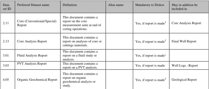
The following list of reports constitutes examples only, and is not to be considered exhaustive:
Table 6.1 Examples of reports and datasets
Data set ID
Preferred Dataset name Definition Alias name Mandatory to Diskos May in addition be included in
2.11 Core (Conventional/Special) Report
This document contains a report on the core measurement suite at end of coring operations.
Yes, if report is made1 Core Analysis Report
2.13 Core Analysis Report
This document contains a report on analyses of core or cuttings materials.
Yes, if report is made1 Final Well Report
3.01 Fluid Analysis Report
This document contains a report on a fluid study or analysis.
Yes, if report is made1 3.03 PVT Analysis Report This document contains a
report on a PVT analysis. Yes, if report is made Well Logs –Report
4.05 Organic Geochemical Report
This document contains a report on organic geochemical analysis or study.
22
5.09 Biostratigraphical DataReport
Report of computed biostratigraphical data, such as palynological and paleontological data, range charts, etc.
Yes, if report is made1 Geological Report
5.11 Geological Report
This document contains a report on a geological analysis or study.
Yes, if report is made1 Final well report
5.13 Lithological Report
This document contains a report on a lithological analysis or study.
Yes, if report is made1 Geological Report Final well report
5.15 Sedimentological Report
This document contains a report on a sedimentological analysis or study.
Yes, if report is made1
Geological Report
5.17 Stratigraphical Report
This document contains a report on a stratigraphical analysis or study.
Yes, if report is made1
Geological Report
6.01 Mud Log Report
All mud, lithology description and hydrocarbon detection and drilling-dynamics data vs depth delivered to the well operator.
Yes, if report is made1 Geological Report
7.13 MWD Report
This document contains a report on the MWD measurement suite at end of drilling operations.
Yes, if report is made1 Well Logs –Report
8.06 Petrophysical Interpretation Report
This document contains a report on the Petrophysical Interpretation for the wellbore.
Yes, if report is made1 Final Well Report
9.09 Formation Pressure Report
This document contains a report on the formation pressure measurements for the wellbore.
Yes, if report is made1 Core Analysis Report
10.09 Production Log Report
This document contains a report of the evaluation results from a production logging job.
Yes, if report is made1 Well Logs -Report
11.07 Well Test Report
This document contains a report on the well test measurements for the wellbore.
Yes, if report is made1 Final Well Report
12.09 Time-Depth-Velocity Report
This document contains a report on the wellbore velocity survey and related calculations.
Yes, if report is made1 Wellbore Seismic Report
13.09 Wellbore Seismic Report
This document contains a report on the wellbore seismic measurement and processing suite at end of wellbore seismic operations.
Yes, if report is made1 Final Well Report
14.01 Completion / Workover Programme
This document contains the completion or work-over programme for the wellbore.
Yes, for all wellbores Drilling Programme
14.03 Completion workover report
This document contains the completion or work-over report for the wellbore.
23
14.03 Completion / WorkoverReport As above Yes, if report is made
1 Final Well Report
14.05 Final Well Report
This document is the operator's official summary report for the completed well.
Well Completion - Report
Yes, for all wellbores
14.13 Drilling Programme
This document contains the drilling programme for the wellbore proposed to the authorities.
Yes, for all wellbores
14.15 Drilling Recommendation
This document contains the official recommendation of the drilling programme for the wellbore as proposed to the authorities.
Yes, for all wellbores
14.17 End of Well Drilling Report
This document is an End of Well report on some aspect of the drilling operatons in the well.
Yes, for all wellbores Final Well Report
14.20 Site Survey Report
This document is a site survey report for the proposed well.
Yes, if report is made1 Final Well Report
14.22 Site Survey Navigation Report
This document is the navigation report for a site survey of the proposed well.
Yes, if report is made1 Site Survey Report
14.24 Discovery evaluation Report
This document is a report evaluating the completed well with proposals for further activities.
discovery evaluation report
Yes, if discovery Well evaluation report
14.26 Well Proposal
Contains geological prognosis, drilling location recommendation, pressure prediction, forming basis for discussion with partners.
Yes, for all wellbores
14.29 Well Logs - Wireline Logging Report
This document contains a report on the wireline log measurement suite at end of logging operations.
Yes, if report is made1 Well Logs -Report
14.29 Well Logs - Report Yes, if report is made1
15.06 Wellpath (Deviation Survey/computed) Report Wellpath (Deviation Survey/computed) Report Yes, for all wellbores Final Well Report
15.08 Final Well Position Report Yes, for all wellbores Final Well Report
15.09 Index of data
Overview of all collected data and analyses
Yes, for all wellbores
16.09 Computed Well Log Report - Wireline (EWL)
This document contains a report on the wireline log measurement run for the specific logging operation.
Wireline logs
report Yes, if report is made1 Well Logs -Report 1 If data and information is acquired, a report needs to be generated and sent to DISKOS as part well reporting.
24
APPENDIX A
Diskos
File Naming Convention and File
Structure for Well Data Files
1.0 Purpose
A file naming convention serves to inform a user of the contents of a file without special applications to examine the file contents. As such, it should be possible to identify files within standard file/directory browsers used by common operating systems. The file name is NOT intended to replace or augment information contained in the file that may be used by database loading applications. The name contains no format information: that is the purpose of the file extension.
2.0 Conventions
A set of naming conventions is given below for 'standard' situations. There are many data files, especially graphical or Information Files where the content is such that a standard name is not appropriate. In such cases, the file name should be chosen so that it clearly conveys the file contents.
3.0 File Name Structure
File names should have the same basic structure:
NAME(Content Information).EXTENSION The use of UPPER-CASE characters throughout is mandatory.
All files are consistently numbered (versioned), starting with ‘_1’ on first occurrence, to ensure correct versioning.
The extension gives information about the format of the file. The following codes are recommended: DLIS, LIS, or SEGY for industry standard binary formats (encapsulated for disk storage where
appropriate)
LAS or SPWLA for such 'standard' ASCII formats
ASC for other non-standard ASCII files
For ‘general industry standard’ graphics files, use the commonly adopted extensions: PDF, (Adobe's
'Portable Document File'), or TIF (here .TIF is 'Tag Image File Format' and NOT 'Tape Image File' as sometimes used for encapsulated log data files).
For specific examples, including ‘Content Information’ see Table A-1.
25
APPENDIX B
Content Information for Specific Data Sets
1.0 Purpose
This Appendix shows what specific attributes (information fields) need to be populated for each of the data sets being reported to Diskos.
2.0 Layout
Each specific data set is referenced using the same number used in the main sections of this document. For example, Raw Well-log data that is in Section 2.1 is also in 2.1 in this Appendix. Exceptions are where both raw and computed data share the same basic contents and structure (core and wellpath data). In these cases, the raw data section number is used.
Note: This Appendix makes reference to the use of ‘Curve Type’ as a generic alias name for specific data curves. Reference values for Curve Type for RAW Well-logs (RAW only at this stage) are the subject of the ENERGISTICS PWLS project. This project is working with TWO related Curve Type attributes: a ‘Curve Type’ and a ‘Property Type’ (based on Schlumberger work). It is an abbreviated version of the ‘Curve Type’ that is used throughout this document.
Also note that lists of Curve Types and other attributes contained in many of the tables in this Appendix may be subject to on-going standards initiatives (ENERGISTICS SIG work). The intention is to maintain these tables as a ‘local’ Norwegian reporting standard in the short-term. If they are adopted by a global standards organisation, these local standards will be modified where appropriate.
3.0 RAW DATA
3.1
WELL-LOG DATA
In addition to using well-log naming standards at the acquisition stage, service companies should be encouraged to unify the way in which these standards are encoded into industry standard formats, particularly DLIS, the recommended delivery format.
3.1.1 Header data
All standard API well-log header data must be completed and coded into the acquisition data format. If this is not possible due to format limitations, or commonly used write and read
applications, then a separate ASCII Information File, in an NPD-approved format, should be used. Particular attention should be paid to filling in the following:
The NPD well naming convention shall be used as the main header entry
Remarks should be fully populated
Service (the tool/software combination used for acquisition)
Program Version (the acquisition software version)
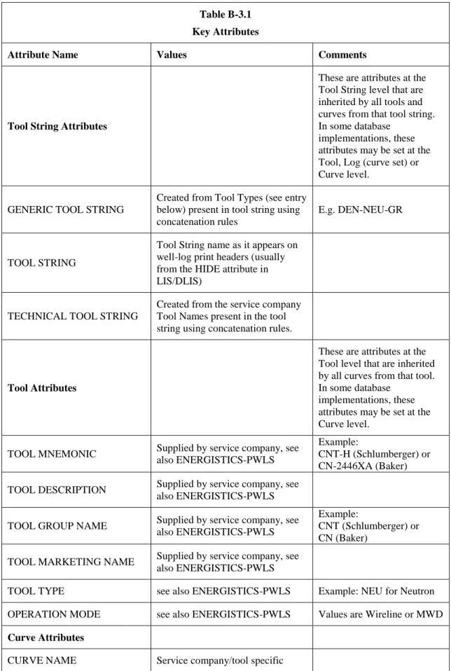
3.1.2 Other Key Attributes
The following Table B3.1 shows other Key Attributes that should be populated. These attributes will facilitate the creation of standard data sets within target databases.
26
Table B-3.1 Key Attributes
Attribute Name Values Comments
Tool String Attributes
These are attributes at the Tool String level that are inherited by all tools and curves from that tool string. In some database
implementations, these attributes may be set at the Tool, Log (curve set) or Curve level.
GENERIC TOOL STRING
Created from Tool Types (see entry below) present in tool string using concatenation rules
E.g. DEN-NEU-GR
TOOL STRING
Tool String name as it appears on well-log print headers (usually from the HIDE attribute in LIS/DLIS)
TECHNICAL TOOL STRING
Created from the service company Tool Names present in the tool string using concatenation rules.
Tool Attributes
These are attributes at the Tool level that are inherited by all curves from that tool. In some database
implementations, these attributes may be set at the Curve level.
TOOL MNEMONIC Supplied by service company, see also ENERGISTICS-PWLS
Example:
CNT-H (Schlumberger) or CN-2446XA (Baker)
TOOL DESCRIPTION Supplied by service company, see also ENERGISTICS-PWLS
TOOL GROUP NAME Supplied by service company, see also ENERGISTICS-PWLS
Example:
CNT (Schlumberger) or CN (Baker)
TOOL MARKETING NAME Supplied by service company, see also ENERGISTICS-PWLS
TOOL TYPE see also ENERGISTICS-PWLS Example: NEU for Neutron OPERATION MODE see also ENERGISTICS-PWLS Values are Wireline or MWD
Curve Attributes
27
CURVE DESCRIPTION Supplied by service company, see also ENERGISTICS-PWLS CURVE BUSINESS VALUE see also ENERGISTICS-PWLS
CURVE TYPE SHORT see also ENERGISTICS-PWLS
Curve Type Short is a token-based classification using 2 to 4 character tokens with ‘dot’ separators. They map 1-to-1 with the Curve Type Long, which is the same as Schlumberger’s ‘Property Type’
CURVE TYPE LONG see also ENERGISTICS-PWLS
The Curve Type Long is a full-length text classification which maps 1-to-1 on the Curve Type Short. CURVE UNIT TYPE see also ENERGISTICS-PWLS
3.1.3 Logging Summary Document
Please refer to the ‘LOGGING SUMMARY (Template)’ sheet in Table A1 for an example. Please note that the logging summary file should be cumulatively generated, i.e. just one (the latest) version of the file should be stored (LOGGING_SUMMARY_1.PDF), incorporating all logging activities in the well. The previous version should be deleted.
3.2
CORE DATA
Raw and Computed Core Data
This section primarily concerns defining Curve Types for conventional core data, although some SCAL measurements are included.
Accompanying information, such as experimental confining pressures, saturation/de-saturation methods and drying, cleaning and fluid extraction methods should be included, in Information Files if necessary.
28
Table B-3.2 Curve Types for Core DataCurve Type Description Comment
CAPI.PRES. Capillary pressure
CEC. Cation exchange capacity
DEN.MAT. Matrix density
DEN.GRN. Grain density
VF.MIN. Mineral volume Volumes from mineralogical
measurements
VF.MIN.DOL. Dolomite Volume
VF.MIN.CALC. Calcite Volume
VF.MIN.SND. Sand Volume
PERM. Permeability
PERM.HOR. Horizontal permeability
PERM.RADI. Radial permeability
PERM.VERT. Vertical permeability
SAMP.NUM.PLUG. Sample (plug) number
POR. Porosity
POR.HE. Helium Porosity
POR.EFF. Effective Porosity
POR.TOT. Total Porosity
SAMP.NUM.CORE Core Number
REL.PERM. Relative permeability
SAT.GAS. Gas saturation
SAT.HYD. Hydrocarbon saturation
SAT.OIL. Oil saturation
SAT.WAT. Water saturation from core SAT.WAT.BND. Bound water saturation
29
3.3
MUDLOG DATA
This section defines Curve Types for common mudlog data. This includes drilling dynamics, mud, lithology and hydrocarbon data (Table B-2.5). Section 2.5.2 covers Lithology coding.
3.3.1 Curve Types
Table B-2.5
Curve Types for Mudlog Data
Curve Type Description Comment
Mud Data
Mud circulation densities, flows and pressures are under Drilling Dynamics data
MUD.RES. Mud resistivity
MUD.RES.IN. Mud resistivity - inflow MUD.RES.OUT. Mud resistivity - outflow
MUD.DEN. Mud density
MUD.FLOW.IN. Mud flow – inflow
MUD.FLOW.OUT. Mud flow – outflow
Drilling Dynamics Data
BIT.SIZE. Bit size
DEPTH. Depth
Probably of little direct use in this context since this implies wireline depth
DEPTH.BIT. Bit depth
DEXP. Drilling exponent
BIT.VEL. Drilling penetration rate
MUD.DEN.ECD. Effective Mud Circulation Density at
TD
MUD.FLOW. Mud flow
MUD.FLOW.IN. Mud flow – inflow
MUD.FLOW.OUT. Mud flow – outflow
MUD.PRES. Mud pressure
30
MUD.PRES.SRF. Mud pressure - surface
PRES. Pressure
PRES.PUMP. Pressure – mud pump
ROP. Rate of Penetration
RPM. Revs per minute
RPM.BIT. Revs per minute - drill bit RPM.BIT.CUM. Revs per minute - drill bit, cumulative
TIME. Time
TIME.BIT. Time - on bit
TIME.CRC. Time – circulation
TIME.CRC.TOT. Time - total circulation time TIME.CRC.BTUP. Time – bottoms-up circulation time
TORQ. Torque
TVD.DRIL. TVD depth from driller
VOL. Volume
VOL.TANK. Tank Volume
WGT. Weight
WOB. Weight on bit
WGT.HK. Hook load
Gas and Hydrocarbon
Data
GAS. Gas
GAS.C1. Gas-methane
GAS.C2. Gas-ethane
GAS.C3. Gas-propane
GAS.C4. Gas – iso butane
GAS.C5. Gas – iso-pentane
GAS.C6. Gas – iso-hexane
GAS.TOT. Total gas
31
GAS.RAT.C12. Gas ratio – methane/ethane GAS.RAT.C13. Gas ratio – methane/propane
HYD.SHOW Hydrocarbon show data Text
Lithology Data
LITH. Lithology NPD Codes (see Section 2.5.2)
LITH.DESC. Lithology description
3.3.2 Lithology Coding
The mudlog interpreted lithology description must be coded and assigned a unique number at each depth according to the NPD "official" lithology definition and nomenclature, a copy of which is shown below. It is assumed that a lithology-type that starts at depth1 has a constant code until a new lithology type starts at depth2 (> depth1). In this way, the lithology descriptions are
represented by one continuous depth indexed, regularly sampled curve, which can then be handled similarly to any of the curves from the mudlog. The lithology description of the cuttings, the one representing the "average" description of the cuttings directly from the mud returns, does not need to be digitised.
NPD Coding System
A digital code has been assigned to the main lithologies as shown. Lithology = (Main lithology * 10) + cement + (modifier / 100). Example: Calcite cemented silty micaceous sandstone: ( 33 * 10 ) + 1 + (21 / 100) = 331.21.
Main Lithologies Cements Modifiers
None 0 None 0 None 0
Conglomerate (general)
10 Calcite 1 Concretions general 10
Grain supported conglomerate
11 Dolomite /Ankerite 2 Calcite concretions 11
Muddy congl. 12 Siderite 3 Dolomite concretions 12 Muddy, sandy, congl. 13 Quartz 4 Siderite concretions 13 Sandy congl. 14 Kaolinite 5 Ooid / pisolite 14 Conglomeratic sandstone 15 Illite 6 Tuffite 15 Conglomeratic muddy sandstone 16 Smectite 7 Bitumenous 16
32
Sedimentary breccia 20 Chlorite 8 Glauconite 17
Sandstone 30 Halite pseudomorph 18
Clayey sandstone 31 Pyrite 19
Muddy sandstone 32 Siderite 20
Silty sandstone 33 Mica 21
Siltstone 40 Kaolinite 22
Sandy siltstone 41 Carbonaceous 23
Fossil siltstone 45 Chamosite 24
Mudstone 50 Phosporite 25
Sandy mudstone 51 Argillaceous 26
Conglomeratic mudstone
52 Calcareous 27
Fissile mudstone 55 Chert 28
Claystone 60 Sulphate 29
Sandy claystone 61 Arenaceous 30
Silty claystone 62 Bioclastic 31
Shale 65 Chalky 32
Silty shale 66 Ferruginous 33
Limestone 70 Fossils 34
Dolomitic limestone 72 Plant Remains 35
Dolostone 74 Lignite 36
Calcareous dolostone 76 Feldspar 37
Chalk 78 Fissile 38 Marl 80 Silty 39 Gypsum 85 Dolomite 40 Anhydrite 86 Gypsum / Anhydrite unspecified 87 Halite 88 Salt, general 89
33
Coal 90
Brown coal 91
Volcanic rock gen. 92
Intrusive rock gen. 93
Silicic plutonic rocks 94
Mafic plutonic rocks 95
Dykes and sills gen. 96
Metamorphic rocks gen. 97
3.4 WELLPATH DATA
3.4.1 Raw and Computed Wellpath Data
This section defines the Curve Types for common wellpath data. The requirement on data completeness is that the data shall uniquely define the entire well (and wellbore) trajectory from a known surface location. Data in the ‘interpreted’ set should be sampled at regular increments of 1m or less, compatible with standard well-log sample rates (typically from 0.10 m upwards). For raw data sets, all important acquisition parameters and directional/elevation information should be included with the data, in Information Files if necessary.
For computed data sets, the computation methods and parameters (including full surface location information) should be reported.
Table B-3.4
Curve Types for Wellpath Data
Curve Type Description Comment
BH.AZIM. * Borehole Azimuth
BH.CURV. * Borehole Curvature
BH.DEVI. * Borehole Deviation/Inclination
DEPTH.MD.* Along-hole depth
DEPTH.TVD. True Vertical Depth
DEPTH.TVD.KB. * True Vertical Depth, KB Ref
DEPTH.TVD.SS. True Vertical Depth, SS Ref
34
COORD.X.GEO. X Geographical Coordinate
COORD.X.OFF. * X Offset
COORD.X.UTM. * X UTM
COORD.Y.GEO. Y Geographical Coordinate
COORD.Y.OFF. * Y Offset
COORD.Y.UTM. * Y UTM
* Mandatory curves
3.5
COMPOSITE WELL LOGS
This section defines the Standard Curve Names and Curve Types to be used for Composited Well-log data. Note that because the Standard Curve Names are generic, there is nearly always a one-to-one correspondence with the Curve Type.
Table B-3.5
Standard Curve Names and Curve Types for Composited Well-log Data Standard Curve Name Curve Type Description/Comment
Primary
AC AC. Sonic
BS BS. Bit Size
CALI CALI. Caliper
DEN DEN. Density
GR GR. Gamma Ray
NEU NEU. Neutron
RDEP RES.DEP. Deep Resistivity
RMED RES.MED. Medium or Shallow resistivity*
RMIC RES.MIC. Microresistivity
SP SP. Spontaneous Potential
Secondary
PEF PEF. Photoelectric Factor
K K. Potassium