37203
Installation
Software Version 1.0xxx
Manual 37203
easY
gen
-1000
Genset Control
WARNING
Read this entire manual and all other publications pertaining to the work to be performed before install-ing, operatinstall-ing, or servicing this equipment. Practice all plant and safety instructions and precautions. Failure to follow instructions can cause personal injury and/or property damage.
The engine, turbine, or other type of prime mover should be equipped with an overspeed (overtempera-ture, or overpressure, where applicable) shutdown device(s), that operates totally independently of the prime mover control device(s) to protect against runaway or damage to the engine, turbine, or other type of prime mover with possible personal injury or loss of life should the mechanical-hydraulic gov-ernor(s) or electric control(s), the actuator(s), fuel control(s), the driving mechanism(s), the linkage(s), or the controlled device(s) fail.
Any unauthorized modifications to or use of this equipment outside its specified mechanical, electrical, or other operating limits may cause personal injury and/or property damage, including damage to the equipment. Any such unauthorized modifications: (i) constitute "misuse" and/or "negligence" within the meaning of the product warranty thereby excluding warranty coverage for any resulting damage, and (ii) invalidate product certifications or listings.
CAUTION
To prevent damage to a control system that uses an alternator or battery-charging device, make sure the charging device is turned off before disconnecting the battery from the system.
Electronic controls contain static-sensitive parts. Observe the following precautions to prevent dam-age to these parts.
• Discharge body static before handling the control (with power to the control turned off, contact a
grounded surface and maintain contact while handling the control).
• Avoid all plastic, vinyl, and Styrofoam (except antistatic versions) around printed circuit boards.
• Do not touch the components or conductors on a printed circuit board with your hands or with
conductive devices.
OUT-OF-DATE PUBLICATION
This publication may have been revised or updated since this copy was produced. To verify that you have the latest revision, be sure to check the Woodward website:
http://www.woodward.com/pubs/current.pdf
The revision level is shown at the bottom of the front cover after the publication number. The latest version of most publications is available at:
http://www.woodward.com/publications
If your publication is not there, please contact your customer service representative to get the latest copy.
Important definitions
WARNING
Indicates a potentially hazardous situation that, if not avoided, could result in death or serious injury.
CAUTION
Indicates a potentially hazardous situation that, if not avoided, could result in damage to equipment.
NOTE
Provides other helpful information that does not fall under the warning or caution categories.
Woodward reserves the right to update any portion of this publication at any time. Information provided by Woodward is believed to be correct and reliable. However, Woodward assumes no responsibility unless otherwise expressly undertaken.
© Woodward
All Rights Reserved.
Content
C
HAPTER1. G
ENERALI
NFORMATION...6
C
HAPTER2.
E
LECTROSTATICD
ISCHARGEA
WARENESS...7
C
HAPTER3. H
OUSING...8
Panel cut-out ... 8
Dimensions ... 9
Side view ...10
Installation ...11
C
HAPTER4. W
IRINGD
IAGRAMS- O
VERVIEW...12
Total overview ...13
Application mode {0} ...16
Application mode {1o} ...17
Application mode {1oc} ...18
Application mode {2oc} ...19
C
HAPTER5. C
ONNECTIONS...20
Power supply...20
Voltage measuring (
FlexRange
) ...21
Voltage measuring: Generator ...21
Mains ...25
Current measuring ...29
Generator...29
Mains current ({2oc} only)... 31
Power measuring ...32
Pickup...33
Discrete inputs ...34
Positive logic (usable alternatively to negative logic - see next chapter) ...34
Negative logic (usable alternatively to positive logic - see previous chapter) ...35
Relay outputs (control outputs and
LogicsManager
) ...36
Analog inputs (
FlexIn
) ...38
Interfaces ...39
Overview ...39
CAN bus (
FlexCAN
)...40
DPC - Direct Configuration Cable...40
C
HAPTER6. T
ECHNICALD
ATA...41
C
HAPTER7. A
CCURACY...44
Illustrations and Tables
Illustrations
Figure 3-1: Housing - panel-board cut-out... 8
Figure 3-2: Housing - dimensions... 9
Figure 3-3: Side view - without clamps ... 10
Figure 3-4: Side view - with clamps ... 10
Figure 4-1: Wiring diagram - total overview ... 13
Figure 4-2: Wiring diagram - application mode {0} - base mode... 16
Figure 4-3: Wiring diagram - application mode {1o} - 1 CB mode ... 17
Figure 4-4: Wiring diagram - application mode {1oc} - 1 CB mode... 18
Figure 4-5: Wiring diagram - application mode {2oc} - 2 CB mode... 19
Figure 5-1: Power supply... 20
Figure 5-2: Power supply - crank waveform at maximum load... 20
Figure 5-3: Voltage measuring (FlexRange) - generator ... 21
Figure 5-4: Voltage measuring (FlexRange) -generator, 3ph 4w... 22
Figure 5-5: Voltage measuring (FlexRange) - generator, 3ph 3w... 23
Figure 5-6: Voltage measuring (FlexRange) - generator, 1ph 3w... 24
Figure 5-7: Voltage measuring (FlexRange) - generator, 1ph 2w... 24
Figure 5-8: Voltage measuring (FlexRange) - mains ... 25
Figure 5-9: Voltage measuring (FlexRange) - mains, 3ph 4w ... 26
Figure 5-10: Voltage measuring (FlexRange) - mains, 3ph 3w ... 27
Figure 5-11: Voltage measuring (FlexRange) - mains, 1ph 3w ... 28
Figure 5-12: Voltage measuring (FlexRange) - mains, 1ph 2w ... 28
Figure 5-13: Current measuring - generator... 29
Figure 5-14: Current measuring - generator, L1 L2 L3 ... 30
Figure 5-15: Current measuring - Generator, Phase Lx ... 30
Figure 5-16: Current measuring - mains current... 31
Figure 5-17: Current measuring - generator, Phase Lx ... 31
Figure 5-18: Power measuring - direction of power ... 32
Figure 5-19: Pickup - principle overview ... 33
Figure 5-20: Pickup input ... 33
Figure 5-21: Minimal necessary input voltage depending on frequency ... 33
Figure 5-22: Discrete inputs - alarm/control inputs [type #1] - positive logic ... 34
Figure 5-23: Discrete inputs - alarm/control inputs [type #2] - positive logic ... 34
Figure 5-24: Discrete inputs - alarm/control inputs [type #1] - negative logic ... 35
Figure 5-25: Discrete input - alarm/control inputs [type #2] - negative logic... 35
Figure 5-26: Relay outputs ... 36
Figure 5-27: Analog inputs (FlexIn) ... 38
Figure 5-28: Interfaces - overview... 39
Figure 5-29: Interfaces - CAN bus (FlexCAN) ... 40
Tables
Table 1-1: Manual - overview... 6
Table 3-1: Housing - panel cut-out ... 8
Table 4-1: Terminal overview, part 1 ... 14
Table 4-2: Terminal overview, part 2 ... 15
Table 5-1: Power supply - terminal assignment... 20
Table 5-2: Voltage measuring (FlexRange) - terminal assignment - generator voltage ... 21
Table 5-3: Voltage measuring (FlexRange) - terminal assignment - generator, 3ph 4w... 22
Table 5-4: Voltage measuring (FlexRange) - terminal assignment - generator, 3ph 3w... 23
Table 5-5: Voltage measuring (FlexRange) - terminal assignment - generator, 1ph 3w... 24
Table 5-6: Voltage measuring (FlexRange) - terminal assignment - generator, 1ph 2w... 24
Table 5-7: Voltage measuring (FlexRange) - terminal assignment - mains voltage... 25
Table 5-8: Voltage measuring (FlexRange) - terminal assignment - mains, 3ph 4w ... 26
Table 5-9: Voltage measuring (FlexRange) - terminal assignment - mains, 3ph 3w ... 27
Table 5-10: Voltage measuring (FlexRange) - terminal assignment - mains, 1ph 3w ... 28
Table 5-11: Voltage measuring (FlexRange) - terminal assignment - mains, 1ph 2w ... 28
Table 5-12: Current measuring - terminal assignment - generator current... 29
Table 5-13: Current measuring - terminal assignment - generator, L1 L2 L3... 30
Table 5-14: Current measuring - terminal assignment - generator, Phase Lx ... 30
Table 5-15: Current measuring - terminal assignment - mains current ... 31
Table 5-16: current measuring - terminal assignment - generator, Phase Lx ... 31
Table 5-17: Pickup - terminal assignment... 33
Table 5-18: Discrete input - terminal assignment - alarm/control input - positive logic... 34
Table 5-19: Discrete input - terminal assignment - alarm/control inputs - negative logic ... 35
Table 5-20: Relay outputs - terminal assignment, part 1 ... 36
Table 5-21: Relay outputs - terminal assignment, part 1 ... 37
Table 5-22: Analog inputs (FlexIn) - terminal assignment ... 38
Chapter 1.
General Information
Type
English
German
easYgen-1000 Series
easYgen-1000 - Installation
this manual
Ö
37203 GR37203
easYgen-1000 - Configuration
37204
GR37204
easYgen-1000 - Operation
37181
GR37181
easYgen-1000 - Application
37205
GR37205
easYgen-1000 - Interfaces
37262
GR37262
Additional Manuals
IKD 1 - Manual
37135
GR37135
Discrete expansion board with 8 discrete inputs and 8 relay outputs that can be coupled via the CAN bus to the control unit. Evalua-tion of the discrete inputs as well as control of the relay outputs is done via the control unit.
IKN 1 - Manual
37136
GR37136
20channel NiCrNi temperature scanner that monitors the temperature values for exceeding or falling below a threshold value, meas-ured through senders on the IKN 1. A configmeas-ured relay on the board of the IKN 1 will trip. The IKN 1 can be coupled with the con-trol unit using the CAN bus to display measuring values as well as alarms.
LeoPC - Manual
37146
GR37146
PC program for visualization, for configuration, for remote control, for data logging, for language upload, for alarm and user man-agement and for manman-agement of the event recorder. This manual describes the use of the program.
LeoPC - Manual
37164
GR37164
PC program for visualization, for configuration, for remote control, for data logging, for language upload, for alarm and user man-agement and for manman-agement of the event recorder. This manual describes the programming of the program.
GW 4 - Manual
37133
GR37133
Gateway for transferring the CAN bus to any other interface or bus.
ST 3 - Manual
37112
GR37112
Control to govern the air fuel ratio of a gas engine. The ratio will be directly measured though a Lambda probe and controlled to a configured value.
Table 1-1: Manual - overview
Intended Use
The unit must only be operated as described in this manual. The prerequisite for a proper and safe
operation of the product is correct transportation, storage, and installation as well as careful operation and
main-tenance.
NOTE
This manual has been developed for a unit fitted with all available options. Inputs/outputs, functions, configuration screens and other details described, which do not exist on your unit may be ignored. The present manual has been prepared to enable the installation and commissioning of the unit. On account of the large variety of parameter settings, it is not possible to cover every possible combina-tion. The manual is therefore only a guide. In case of incorrect entries or a total loss of functions, the default settings can be taken from the enclosed list of parameters.
Chapter 2.
Electrostatic Discharge Awareness
All electronic equipment is static-sensitive, some components more than others. To protect these components
from static damage, you must take special precautions to minimize or eliminate electrostatic discharges.
Follow these precautions when working with or near the control.
1.
Before doing maintenance on the electronic control, discharge the static electricity on your body to
ground by touching and holding a grounded metal object (pipes, cabinets, equipment, etc.).
2.
Avoid the build-up of static electricity on your body by not wearing clothing made of synthetic materials.
Wear cotton or cotton-blend materials as much as possible because these do not store static electric
char-ges as much as synthetics.
3.
Keep plastic, vinyl, and Styrofoam materials (such as plastic or Styrofoam cups, cup holders, cigarette
packages, cellophane wrappers, vinyl books or folders, plastic bottles, and plastic ash trays) away from
the control, the modules, and the work area as much as possible.
4.
Opening the control cover may void the unit warranty.
Do not remove the printed circuit board (PCB) from the control cabinet unless absolutely necessary. If
you must remove the PCB from the control cabinet, follow these precautions:
•
Do not touch any part of the PCB except the edges.
•
Do not touch the electrical conductors, the connectors, or the components with conductive devices or
with your hands.
•
When replacing a PCB, keep the new PCB in the plastic antistatic protective bag it comes in until you
are ready to install it. Immediately after removing the old PCB from the control cabinet, place it in the
antistatic protective bag.
CAUTION
To prevent damage to electronic components caused by improper handling, read and observe the
pre-cautions in Woodward manual 82715, Guide for Handling and Protection of Electronic Controls, Printed
Chapter 3.
Housing
Panel cut-out
≡≡≡≡≡≡≡≡≡≡≡≡≡≡≡≡≡≡≡≡≡≡≡≡≡
h' h H
b
B
b'
Figure 3-1: Housing - panel-board cut-out
Measure Description Tolerance
H Height Total 144 mm --- h Panel cut-out 138 mm + 1.0 mm h' Housing dimension 136 mm B Width Total 192 mm --- b Panel cut-out 186 mm + 1.1 mm b' Housing dimension 185 mm Depth Total 60.5 ---
Dimensions
≡≡≡≡≡≡≡≡≡≡≡≡≡≡≡≡≡≡≡≡≡≡≡≡≡
58
57
56
55
54
53
52
51
50
49
48
46
45
44
43
42
41
40
39
38
37
36
35
34
33
32
31
30
12
3
4
5
6
7
8
9
10
11
12
13
14
15
16
17
18
19
20
21
22
23
24
25
26
27
28
29
47
NOTE
Conn
ec
ted
i
ndu
ct
anc
es (e
. g.
Coil
s o
f ope
ratin
g c
ur
ren
t
or u
nd
erv
ol
tag
e
tri
pping
dev
ices,
au
xilia
ry co
nta
ct
ors
and
po
wer
c
ont
ac
tor
s) mu
st b
e wir
ed
with
an ap
pro
pr
iat
e
inte
rf
ere
nc
e p
ro
tec
tion.
WARN
IN
G
Befo
re
di
sc
onn
ec
tin
g the
sec
ondar
y t
ermin
als o
f t
he
cu
rr
ent
tran
sf
orm
er
or
t
he
conne
ctio
ns of
th
e tra
nsfor
mer
a
t
the
un
it,
m
ake
s
ure
that
the
tran
sfo
rmer
is
shor
t-cir
cu
ite
d.
Dime
ns
ion
s
Cuto
ut
[W
xH
]:1
86
x
138 m
m
Tota
l
[Wx
Hx
D]:
1
92
x 144
x 6
2 mm
144 mm
136 mm
19
2 mm
18
5 mm
62
m
m
54
m
m
Ba
ck
V
iew
Vi
ew
fr
om
r
ig
ht
PC C
on
figur
ation
Plug
2003-09-03 | e asYgen-1000 Dim en sio ns eYg10 00w w-360 3-ab. sk fSide view
≡≡≡≡≡≡≡≡≡≡≡≡≡≡≡≡≡≡≡≡≡≡≡≡≡
Cabinet
Front frame
Housing
Mounting cones
Figure 3-3: Side view - without clamps
Cabinet
Front frame
Housing
Mounting cones
Mounting clamp
Installation
≡≡≡≡≡≡≡≡≡≡≡≡≡≡≡≡≡≡≡≡≡≡≡≡≡
For installation into a panel door please proceed as follows:
1.
Panel cut-out
Cut out the panel according to the dimensions in Figure 3-2.
bh H B
2.
Remove terminals
Loose the side screw and remove the wiring terminals from the unit.
Remove the terminals
3.
Insert unit into cut-out
Insert the unit into the panel cut-out. Verify that the unit fits correctly in
the cut-out. If the panel cut-out is not big enough, enlarge it
accord-ingly.
Move housing into panel
a)
Attach clamp here4.
Attach mounting clamps
Rotate clamps according to the picture on the right until they snap into
the mounting cones.
b)
Rotate clamp until front nut of the clamp locks into front cone5.
Screw clamps
Tighten the screw clamps until the housing is pressed and fixed against
the panel. Be careful not to over tighten the clamps which can unsnap
the frame from the housing. If this happens remove the unit from the
panel and reattach the frame by pressing firmly against the housing.
Screw down until the housing fits into the panel
6.
Reattach terminals
Reattach the green wiring terminals, using the side screw to secure.
Attach the terminals
Note:
Using the gasket kit (P/N 8923-1043) increases the IP protection from IP42 to IP54 from front. Mounting
of the gasket is described in the manual supplied with the gasket kit.
Chapter 4.
Wiring Diagrams - Overview
NOTE
Please see manual 37181 "Operations Manual" for selection of the application mode. Depending on this setting different terminals will be used.
•
Application mode {0} - [BM] - Base Mode - page 16
- Measuring of engine/generator parameters (e. g. voltages, currents, coolant temp., oil pressure, etc.)
- Engine start/stop
•
Application mode {1o} - [GCB open] - 1-CB-Mode - page 17
- Measuring of engine/generator parameters (e. g. voltages, currents, coolant temp., oil pressure, etc.)
- Engine start/stop
- Engine/generator protection (relay output to open GCB)
•
Application mode {1oc} - [GCB open/close] - 1-CB-Mode - page 18
- Measuring of engine/generator parameters (e. g. voltages, currents, coolant temp., oil pressure, etc.)
- Engine start/stop
- Engine/generator protection (relay output to open GCB)
- GCB operation (relay output to close GCB)
•
Application mode {2oc} - [GCB/MCB open/close] - 2-CB-Mode - page 19
- Measuring of engine/generator parameters (e. g. voltages, currents, coolant temp., oil pressure, etc.)
- Engine start/stop
- Engine/generator protection (relay output to open GCB)
- GCB operation (relay output to close GCB)
- MCB operation (relay output to open and close the MCB)
Total overview
≡≡≡≡≡≡≡≡≡≡≡≡≡≡≡≡≡≡≡≡≡≡≡≡≡
G
1
12/24 Vdc
2004-02-13 | easYgen-1500 Wiring Diagram eYg1500ww-0704-ap.skf
4 5 2 3 5 6 7 8 28 29 11 12 13 48 49 50 51 52 53 54 55 ../1 A or ../5 A 0 Vdc Dr ive
Subject to technical mocifications.
Generator current L3 Generator current L2 Generator current L1 Generator voltage L1 Pickup Analog input 1 [T1] VDO & resistive & 0/4..20 mA
The sock et fo r t he PC co nf ig ur at ion i s si tuat ed o n th e back o f t he i te m .T hi s i s w he re t he DP C has t o be p lu gged in . Common (terminals 51-58) Discrete input [D2] - Alarm input (LogicsManager) Discrete input [D1] - Alarm input (LogicsManager) Relay [R6] (LogicsManager) - Auxiliary services 36 37 34 CAN bus CAN-H CAN-L Analog input 2 [T2] VDO & resistive & 0/4..20 mA Common 10 9 switching/inductive 480 Vac 120 Vac 26 27 Generator voltage L2 480 Vac 120 Vac 24 25 Generator voltage L3 480 Vac 120 Vac 22 23 480 Vac 120 Vac Generator voltage N ../1 A or ../5 A ../1 A or ../5 A Common Discrete input [D3] - Alarm input (LogicsManager) Discrete input [D4] - Alarm input (LogicsManager) Discrete input [D5] - Alarm input (LogicsManager)
34 33 32 35 Common (terminals 30-34) Relay [R5] (LogicsManager) - Diesel: Preglow; Gas: Ignition ON Relay [R4]
- Diesel: Fuel relay; Gas: Gas valve Relay [R3]
- Crank
31
Relay [R2] (LogicsManager) - Alarm class C/D/E/F active
30 Relay [R1] (LogicsManager) - Centralized alarm Relay [R7] - LogicsManager or - "Command: open GCB" 38 39 Relay [R8] - LogicsManager or - "Command: close MCB" 40 41 Relay [R11]
- Readiness for operation 46
47 3 GND Battery con fig ura bl e dur in g se tu p (N O /N C) #1 NO/NC#1 NO/NC#1 NO/NC#1 NO/NC#1 #1 #2 Ba tte ry or an ot he r po we r s uppl y; te rm in al 50 is po s. o r n eg . s ig nal #2 NO/NC Relay [R10] - LogicsManager or - "Command: close GCB" 44 45 Relay [R9] - LogicsManager or - "Command: open MCB" 42 43 6 56
Discrete input [D6] - Alarm input (LogMan) or "Enable MCB"
7 57
Discrete input [D7] - Alarm input (LogMan) or "Reply: MCB is open"
8 58
Discrete input [D8] - Alarm input (LogMan)
or "Reply: GCB is open" NO/NC#1 NO/NC#1 NO/NC#1 3 3 MCB Reply: MCB is open => use discrete input [D7] Enable MCB => use discrete input [D6] Command: open MCB => use relay [R9] Mains current L1 or Ground current ../1 A or ../5 A 2 1 20 21 18 19 16 17 14 15 {2oc} Mains voltage L1 480 Vac 120 Vac {2oc} Mains voltage L2 480 Vac 120 Vac {2oc} Mains voltage L3 480 Vac 120 Vac 480 Vac 120 Vac GND GCB Reply: GCB is open => use discrete input [D8] Command: close GCB => use relay [R10]
{2oc} Mains voltage N
The Mode of the control can be configured alternatively as an:
{0} - Measuring transducer/engine control [0CB] {1o} - 1-CB-control [GCB open] {1oc} - 1-CB-control [GCB open/close] {2oc} - 2-CB-control [GCB/MCB open/close] Depending on the setting you have different I/O's available, respectively the control can operate the breakers for protection/closing or not. Model easYgen-1500 - Flush-mounting - P/N 8440-1330 & 8440-1544 = ../5 A - P/N 8440-1331 & 8440-1545 = ../1 A Model easYgen-1400 - DIN-rail mounting - P/N 8440-1389 = ../5 A - P/N 8440-1390 = ../1 A
ea
sY
ge
n-150
0/
1400
FlexApp / DynamicsLCD FlexR an ge FlexIn FlexCAN Fle xR an ge Lo gi cs M an ag er Lo gi cs Ma na ge r Command: close MCB => use relay [R8] Command: open GCB => use relay [R7] Fl ex A pp Fl exA pp 1 2 3 3 G1 {0} GCB 3 3 {1o} GCB 3 3 {1oc} 3 1 MCB GCB 3 3 {2oc} S/S G1 S/S G1 S/S G1 S/S open open/ c los e open/ c los e(G
en
set
C
ont
rol
)
Battery Sender SenderWiring differences depending on application mode selection
The control can be programmed for one of four possible application modes. Depending on which mode is
se-lected, certain terminals may have a different function. The following table lists all of the control terminals and
their associated function for each of the four application modes.
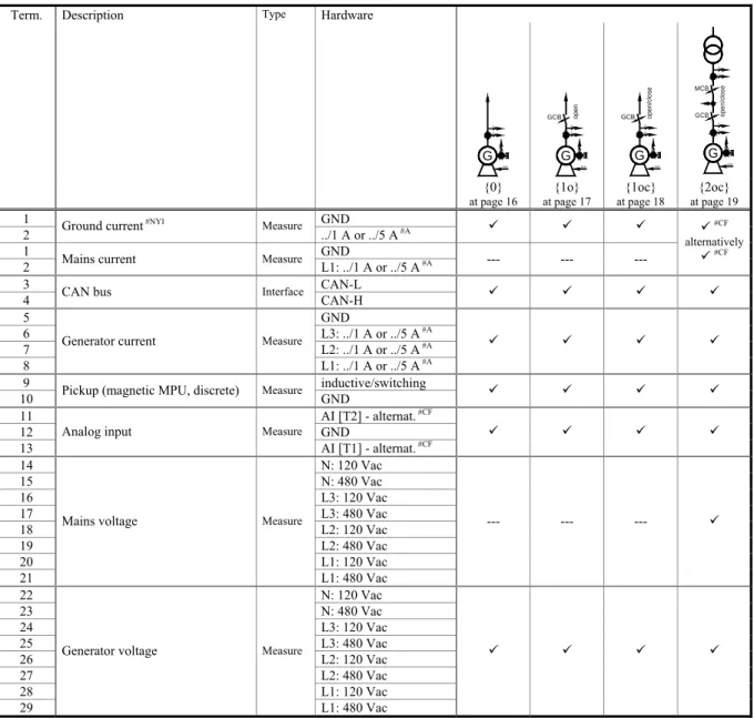
Term. Description Type Hardware
3 3 G 1 S/S 3 3 GCB G1 S/S op en GCB 3 3 G 1 S/S ope n/ clos e 3 1 MCB GCB 3 3 G1 S/S op en /c lo s e {0}
at page 16 at page 17 {1o} at page 18 {1oc} at page 19 {2oc}
1 GND 2 Ground current
#NYI Measure
../1 A or ../5 A #A 9 9 9 1 GND
2 Mains current Measure L1: ../1 A or ../5 A #A --- --- --- 9#CF
alternatively
9#CF 3 CAN-L
4 CAN bus Interface CAN-H 9 9 9 9
5 GND
6 L3: ../1 A or ../5 A #A
7 L2: ../1 A or ../5 A #A
8
Generator current Measure
L1: ../1 A or ../5 A #A
9 9 9 9
9 inductive/switching 10 Pickup (magnetic MPU, discrete) Measure GND 9 9 9 9
11 AI [T2] - alternat. #CF
12 GND 13
Analog input Measure
AI [T1] - alternat. #CF 9 9 9 9 14 N: 120 Vac 15 N: 480 Vac 16 L3: 120 Vac 17 L3: 480 Vac 18 L2: 120 Vac 19 L2: 480 Vac 20 L1: 120 Vac 21
Mains voltage Measure
L1: 480 Vac --- --- --- 9 22 N: 120 Vac 23 N: 480 Vac 24 L3: 120 Vac 25 L3: 480 Vac 26 L2: 120 Vac 27 L2: 480 Vac 28 L1: 120 Vac 29
Generator voltage Measure
L1: 480 Vac
9 9 9 9
#A - alternatively (different hardware); #NYI - not yet implemented; #CF - selection during and through configuration
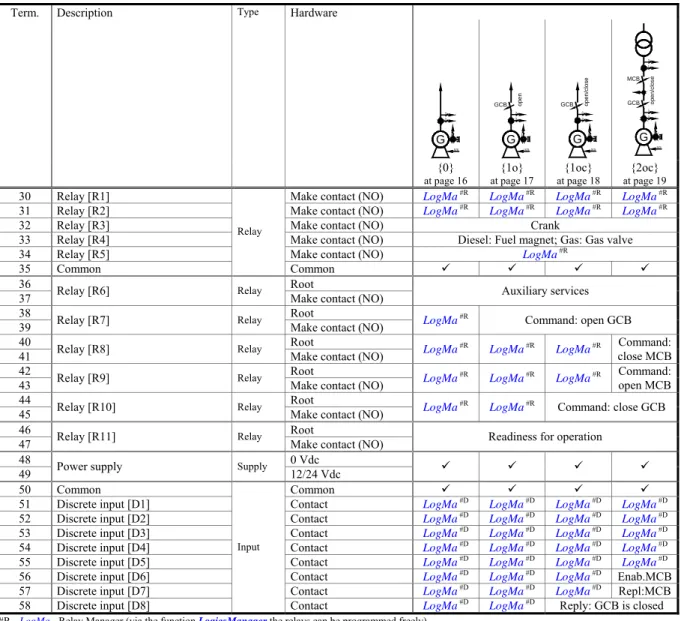
Term. Description Type Hardware 3 3 G 1 S/S 3 3 GCB G1 S/S op en GCB 3 3 G 1 S/S ope n/ clos e 3 1 MCB GCB 3 3 G1 S/S op en /c lo s e {0} at page 16 {1o} at page 17 {1oc} at page 18 {2oc} at page 19
30 Relay [R1] Make contact (NO) LogMa #R LogMa #R LogMa #R LogMa #R
31 Relay [R2] Make contact (NO) LogMa #R LogMa #R LogMa #R LogMa #R
32 Relay [R3] Make contact (NO) Crank
33 Relay [R4] Make contact (NO) Diesel: Fuel magnet; Gas: Gas valve 34 Relay [R5] Make contact (NO) LogMa #R
35 Common
Relay
Common 9 9 9 9
36 Root 37 Relay [R6] Relay Make contact (NO) Auxiliary services 38 Root 39 Relay [R7] Relay Make contact (NO) LogMa
#R Command: open GCB 40 Root
41 Relay [R8] Relay Make contact (NO) LogMa #R
LogMa #R LogMa #R close MCBCommand:
42 Root 43 Relay [R9] Relay Make contact (NO) LogMa
#R
LogMa #R LogMa #R Command: open MCB
44 Root 45 Relay [R10] Relay Make contact (NO) LogMa
#R
LogMa #R Command: close GCB
46 Root 47 Relay [R11] Relay Make contact (NO) Readiness for operation
48 0 Vdc
49 Power supply Supply 12/24 Vdc 9 9 9 9
50 Common Common 9 9 9 9
51 Discrete input [D1] Contact LogMa #D LogMa #D LogMa #D LogMa #D
52 Discrete input [D2] Contact LogMa #D LogMa #D LogMa #D LogMa #D
53 Discrete input [D3] Contact LogMa #D LogMa #D LogMa #D LogMa #D
54 Discrete input [D4] Contact LogMa #D LogMa #D LogMa #D LogMa #D
55 Discrete input [D5] Contact LogMa #D LogMa #D LogMa #D LogMa #D
56 Discrete input [D6] Contact LogMa #D LogMa #D LogMa #D Enab.MCB 57 Discrete input [D7] Contact LogMa #D LogMa #D LogMa #D Repl:MCB
58 Discrete input [D8]
Input
Contact LogMa #D LogMa #D Reply: GCB is closed
#R - LogMa - Relay Manager (via the function LogicsManager the relays can be programmed freely)
#D - LogMa - Discrete Input Manager (via the function LogicsManager this discrete inputs can be programmed freely)
Repl.MCB..Reply: MCB is closed Enab.MCB..Enable MCB
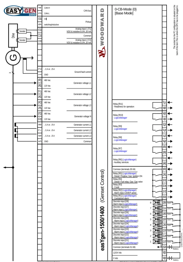
Application mode {0}
≡≡≡≡≡≡≡≡≡≡≡≡≡≡≡≡≡≡≡≡≡≡≡≡≡
G
1
12/24 Vdc
2004-02-13 | easYgen-1500 Wiring Diagram eYg1500ww-0704-ap.skf
4 5 2 3 5 6 7 8 28 29 11 12 13 48 49 50 51 52 53 54 55 ../1 A or ../5 A 0 Vdc Dr ive
Subject to technical mocifications.
Generator current L3 Generator current L2 Generator current L1 Generator voltage L1 Pickup Analog input 1 [T1] VDO & resistive & 0/4..20 mA
The sock et fo r t he PC co nf ig ur at ion i s si tuat ed o n th e back o f t he i te m .T hi s i s w he re t he DP C has t o be p lu gged in . Common (terminals 51-58) Discrete input [D2] - Alarm input (LogicsManager) Discrete input [D1] - Alarm input (LogicsManager) Relay [R6] (LogicsManager) - Auxiliary services 36 37 34 CAN bus CAN-H CAN-L Analog input 2 [T2] VDO & resistive & 0/4..20 mA Common 10 9 switching/inductive 480 Vac 120 Vac 26 27 Generator voltage L2 480 Vac 120 Vac 24 25 Generator voltage L3 480 Vac 120 Vac 22 23 480 Vac 120 Vac Generator voltage N ../1 A or ../5 A ../1 A or ../5 A Common Discrete input [D3] - Alarm input (LogicsManager) Discrete input [D4] - Alarm input (LogicsManager) Discrete input [D5] - Alarm input (LogicsManager)
34 33 32 35 Common (terminals 30-34) Relay [R5] (LogicsManager) - Diesel: Preglow; Gas: Ignition ON Relay [R4]
- Diesel: Fuel relay; Gas: Gas valve Relay [R3]
- Crank
31
Relay [R2] (LogicsManager) - Alarm class C/D/E/F active
30
Relay [R1] (LogicsManager) - Centralized alarm Relay [R11]
- Readiness for operation 46
47 3 GND Relay [R10] - LogicsManager 44 45 Relay [R9] - LogicsManager 42 43 6 56 Discrete input [D6] Alarm input (LogicsManager)
7 57
Discrete input [D7] Alarm input (LogicsManager)
8 58
Discrete input [D8] Alarm input (LogicsManager)
Battery NO/NC#1 con fig ura bl e dur in g se tu p (N O /N C) #1 NO/NC#1 NO/NC#1 NO/NC#1 NO/NC#1 NO/NC#1 NO/NC#1 #1 #2 Ba tte ry or an ot he r po we r s uppl y; te rm in al 50 is po s. o r n eg . s ig nal #2 2 1 ../1 A or ../5 A GND NO/NC
ea
sY
ge
n-150
0/
1400
Relay [R8] - LogicsManager 40 41 Relay [R7] - LogicsManager 38 39(G
en
set
C
ont
rol
)
0-CB-Mode {0} [Base Mode]Ground fault current
Battery
Sender Sender
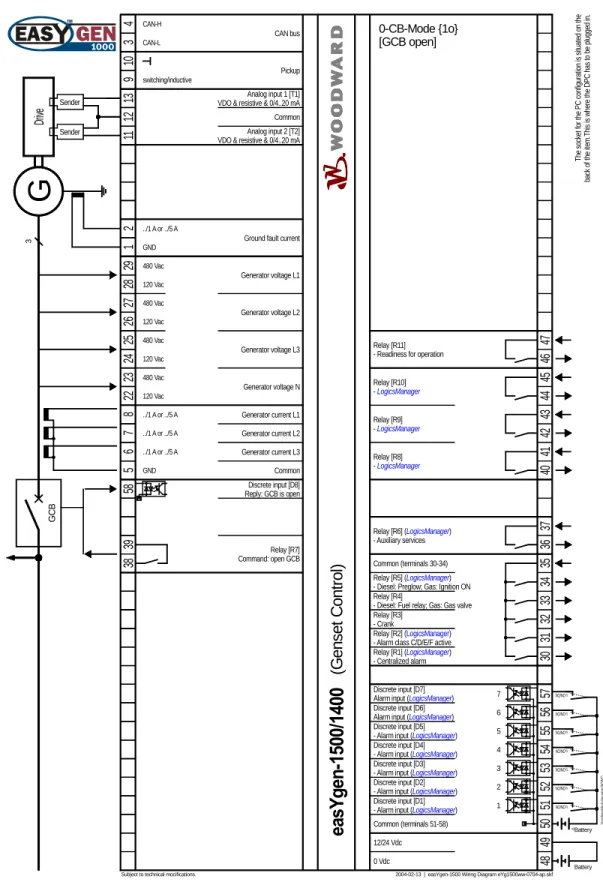
Application mode {1o}
≡≡≡≡≡≡≡≡≡≡≡≡≡≡≡≡≡≡≡≡≡≡≡≡≡
G
1
12/24 Vdc
2004-02-13 | easYgen-1500 Wiring Diagram eYg1500ww-0704-ap.skf
4 5 2 3 5 6 7 8 28 29 11 12 13 48 49 50 51 52 53 54 55 ../1 A or ../5 A 0 Vdc Dr ive
Subject to technical mocifications.
Generator current L3 Generator current L2 Generator current L1 Generator voltage L1 Pickup Analog input 1 [T1] VDO & resistive & 0/4..20 mA
The sock et fo r t he PC co nf ig ur at ion i s si tuat ed o n th e back o f t he i te m .T hi s i s w he re t he DP C has t o be p lu gged in . Common (terminals 51-58) Discrete input [D2] - Alarm input (LogicsManager) Discrete input [D1] - Alarm input (LogicsManager) Relay [R6] (LogicsManager) - Auxiliary services 36 37 34 CAN bus CAN-H CAN-L Analog input 2 [T2] VDO & resistive & 0/4..20 mA Common 10 9 switching/inductive 480 Vac 120 Vac 26 27 Generator voltage L2 480 Vac 120 Vac 24 25 Generator voltage L3 480 Vac 120 Vac 22 23 480 Vac 120 Vac Generator voltage N ../1 A or ../5 A ../1 A or ../5 A Common Discrete input [D3] - Alarm input (LogicsManager) Discrete input [D4] - Alarm input (LogicsManager) Discrete input [D5] - Alarm input (LogicsManager)
34 33 32 35 Common (terminals 30-34) Relay [R5] (LogicsManager) - Diesel: Preglow; Gas: Ignition ON Relay [R4]
- Diesel: Fuel relay; Gas: Gas valve Relay [R3]
- Crank
31
Relay [R2] (LogicsManager) - Alarm class C/D/E/F active
30
Relay [R1] (LogicsManager) - Centralized alarm Relay [R11]
- Readiness for operation 46
47 3 GND Battery con fig ura bl e dur in g se tu p (N O /N C) #1 NO/NC#1 NO/NC#1 NO/NC#1 NO/NC#1 #1 #2 Ba tte ry or an ot he r po we r s uppl y; te rm in al 50 is po s. o r n eg . s ig nal #2 NO/NC
ea
sY
ge
n-150
0/
1400
58 GCB Discrete input [D8] Reply: GCB is open Relay [R9] - LogicsManager 42 43 6 7 56 57 Discrete input [D6] Alarm input (LogicsManager) Discrete input [D7]Alarm input (LogicsManager) #1 NO/NC#1
Ground fault current
2 1 ../1 A or ../5 A GND NO/NC Relay [R8] - LogicsManager 40 41 38 39 Relay [R7] Command: open GCB Relay [R10] - LogicsManager 44 45
(G
en
set
C
ont
rol
)
0-CB-Mode {1o} [GCB open] Battery Sender SenderApplication mode {1oc}
≡≡≡≡≡≡≡≡≡≡≡≡≡≡≡≡≡≡≡≡≡≡≡≡≡
G
1
12/24 Vdc
2004-02-13 | easYgen-1500 Wiring Diagram eYg1500ww-0704-ap.skf
4 5 2 3 44 45 58 5 6 7 8 28 29 11 12 13 48 49 50 51 52 53 54 55 ../1 A or ../5 A 0 Vdc Dr ive
Subject to technical mocifications.
GCB Discrete input [D8] Reply: GCB is open Generator current L3 Generator current L2 Generator current L1 Generator voltage L1 Pickup Analog input 1 [T1] VDO & resistive & 0/4..20 mA
Relay [R10] Command: close GCB The sock et fo r t he PC co nf ig ur at ion i s si tuat ed o n th e back o f t he i te m .T hi s i s w he re t he DP C has t o be p lu gged in . Common (terminals 51-58) Discrete input [D2] - Alarm input (LogicsManager) Discrete input [D1] - Alarm input (LogicsManager) Relay [R6] (LogicsManager) - Auxiliary services 36 37 34 CAN bus CAN-H CAN-L Analog input 2 [T2] VDO & resistive & 0/4..20 mA Common 10 9 switching/inductive 480 Vac 120 Vac 26 27 Generator voltage L2 480 Vac 120 Vac 24 25 Generator voltage L3 480 Vac 120 Vac 22 23 480 Vac 120 Vac Generator voltage N ../1 A or ../5 A ../1 A or ../5 A Common Discrete input [D3] - Alarm input (LogicsManager) Discrete input [D4] - Alarm input (LogicsManager) Discrete input [D5] - Alarm input (LogicsManager)
34 33 32 35 Common (terminals 30-34) Relay [R5] (LogicsManager) - Diesel: Preglow; Gas: Ignition ON Relay [R4]
- Diesel: Fuel relay; Gas: Gas valve Relay [R3]
- Crank
31
Relay [R2] (LogicsManager) - Alarm class C/D/E/F active
30
Relay [R1] (LogicsManager) - Centralized alarm Relay [R11]
- Readiness for operation 46
47 3 GND Relay [R9] - LogicsManager 42 43 6 7 56 57 Discrete input [D6] Alarm input (LogicsManager) Discrete input [D7] Alarm input (LogicsManager)
Battery con fig ura bl e dur in g se tu p (N O /N C) #1 NO/NC#1 NO/NC#1 NO/NC#1 NO/NC#1 #1 #2 Ba tte ry or an ot he r po we r s uppl y; te rm in al 50 is po s. o r n eg . s ig nal #2 #1 NO/NC#1
Ground fault current
2 1 ../1 A or ../5 A GND NO/NC NO/NC
ea
sY
ge
n-150
0/
1400
Relay [R8] - LogicsManager 40 41 38 39 Relay [R7] Command: open GCB(G
en
set
C
ont
rol
)
1-CB-Mode {1oc} [GCB open/close] Battery Sender SenderApplication mode {2oc}
≡≡≡≡≡≡≡≡≡≡≡≡≡≡≡≡≡≡≡≡≡≡≡≡≡
3 3G
1 12/24 Vdc2004-02-13 | easYgen-1500 Wiring Diagram eYg1500ww-0704-ap.skf
4 5 2 3 43 56 57 5 6 7 8 28 29 11 12 13 48 49 50 51 52 53 54 55 ../1 A or ../5 A 0 Vdc Dr ive MCB
Subject to technical mocifications.
Generator current L3 Generator current L2 Generator current L1 Generator voltage L1 Pickup Analog input 1 [T1] VDO & resistive & 0/4..20 mA
The sock et fo r t he PC co nf ig ur at ion i s si tuat ed o n th e back o f t he i te m .T hi s i s w he re t he DP C has t o be p lu gged in . Discrete input [D7] Reply: MCB is open Discrete input [D6] Enable MCB Relay [R9] Command: open MCB Common (terminals 51-58) Discrete input [D2] - Alarm input (LogicsManager) Discrete input [D1] - Alarm input (LogicsManager) Relay [R6] (LogicsManager) - Auxiliary services 36 37 34 CAN bus CAN-H CAN-L Analog input 2 [T2] VDO & resistive & 0/4..20 mA Common 10 9 switching/inductive 480 Vac 120 Vac 26 27 Generator voltage L2 480 Vac 120 Vac 24 25 Generator voltage L3 480 Vac 120 Vac 22 23 480 Vac 120 Vac Generator voltage N ../1 A or ../5 A ../1 A or ../5 A Common Mains current L1 or Ground fault current
../1 A or ../5 A 42 2 1 20 21 18 19 16 17 14 15 Mains voltage L1 480 Vac 120 Vac Mains voltage L2 480 Vac 120 Vac Mains voltage L3 480 Vac 120 Vac 480 Vac 120 Vac Mains voltage N Discrete input [D3] - Alarm input (LogicsManager) Discrete input [D4] - Alarm input (LogicsManager) Discrete input [D5] - Alarm input (LogicsManager)
34 33 32 35 Common (terminals 30-34) Relay [R5] (LogicsManager) - Diesel: Preglow; Gas: Ignition ON Relay [R4]
- Diesel: Fuel relay; Gas: Gas valve Relay [R3]
- Crank
31
Relay [R2] (LogicsManager) - Alarm class C/D/E/F active
30
Relay [R1] (LogicsManager) - Centralized alarm Relay [R11]
- Readiness for operation 46
47 3 GND GND Battery con fig ura bl e dur in g se tu p (N O /N C) #1 NO/NC#1 NO/NC#1 NO/NC#1 NO/NC#1 #1 #2 Ba tte ry or an ot he r po we r s uppl y; te rm in al 50 is po s. o r n eg . s ig nal #2 NO/NC 44 45 58 GCB Discrete input [D8] Reply: GCB is open Relay [R10] Command: close GCB
ea
sY
ge
n-150
0/
1400
1 2 38 39 Relay [R7] Command: open GCB 41 40 Relay [R8] Command: close MCB(G
en
set
C
ont
rol
)
2-CB-Mode {2oc} [GCB/MCB open/close] Battery Sender SenderChapter 5.
Connections
Power supply
≡≡≡≡≡≡≡≡≡≡≡≡≡≡≡≡≡≡≡≡≡≡≡≡≡
49 48 0 Vdc Power supply 6.5..40.0 Vdc 6.5..40.0 VdcFigure 5-1: Power supply
Connect in application mode ...
[BM] [0CB] [1CB] [2CB] Terminal Description Amax
9 9 9 9 48 0 Vdc reference potential 2.5 mm²
9 9 9 9 49 6.5..40.0 Vdc, 15 W 2.5 mm²
Table 5-1: Power supply - terminal assignment
[ms] -50 0 50 100 150 200 250 300 350 [V] 9.0 10.0 11.0 12.0 P o w e r S u p p ly 8.0 7.0 6.0 5.0 4.0 3.0 2.0 1.0 0.0 Time Initial voltage = 10.5 Vdc 0.0 Vdc für 10 ms Continuous voltage = min. 6.5 Vdc
Continuous voltage range = 6.5-40.0 Vdc
Figure 5-2: Power supply - crank waveform at maximum load
Voltage measuring (
FlexRange
)
≡≡≡≡≡≡≡≡≡≡≡≡≡≡≡≡≡≡≡≡≡≡≡≡≡
NOTE
The measuring voltages may only be attached alternatively either on the input for 120 Vac or to the in-put for 480 Vac. If both measuring inin-puts are installed at the same time, this will cause wrong meas-urements!
Voltage measuring: Generator
L1 L2 L3 N Gene ra to r vo ltag e (phase voltage) GCB 26 N / Vcom 27 28 29 L1 / Va L2 / Vb L3 / Vc 23 24 25 22 480 Vac 120 Vac 120 Vac 480 Vac 120 Vac 480 Vac 120 Vac 480 Vac 480 Vac 120 Vac 480 Vac 120 Vac 480 Vac 120 Vac 480 Vac 120 Vac
G
3~Figure 5-3: Voltage measuring (FlexRange) - generator
Connect in application mode ...
[BM] [0CB] [1CB] [2CB] Terminal Description Amax
9 9 9 9 22 120 Vac 2.5 mm²
9 9 9 9 23 Generator voltage - phase N 480 Vac 2.5 mm²
9 9 9 9 24 120 Vac 2.5 mm²
9 9 9 9 25 Generator voltage - phase L3 480 Vac 2.5 mm²
9 9 9 9 26 120 Vac 2.5 mm²
9 9 9 9 27 Generator voltage - phase L2 480 Vac 2.5 mm²
9 9 9 9 28 120 Vac 2.5 mm²
9 9 9 9 29 Generator voltage - phase L1 480 Vac 2.5 mm² Table 5-2: Voltage measuring (FlexRange) - terminal assignment - generator voltage
Voltage measuring: Generator, parameter setting '
3ph 4w
' (3phase, 4wire)
L1 L2 N L3 U1 U2 U V N V2 V1 W W2 W1 L1 L2 N L3 U1 U2 U V N W6 W5 V6 V5 U5 U6 V2 V1 W W2 W1 L1 L2 N L3 U1 U2 U V N V6 V5 U5 U6 W W6 W5 V2 V1 W2 W1L1 L2 L3 N V1 V2 W6 W5 U1 U2 V5 V6 U V W N W2 W1 U5 U6
Figure 5-4: Voltage measuring (FlexRange) -generator, 3ph 4w
3ph 4w Wiring terminals Notes
Rated voltage 120 Vac 480 Vac
Range (max.) 0..150 Vac 0..600 Vac 1
easYgen 28 26 24 22 29 27 25 23
Phase L1 L2 L3 N L1 L2 L3 N
Table 5-3: Voltage measuring (FlexRange) - terminal assignment - generator, 3ph 4w
1 For different voltage systems different wiring terminals have to be used. A simultaneous use of the N terminal is not possible can can lead to wrong measuring.
Voltage measuring: Generator, parameter setting '
3ph 3w
' (3phase, 3wire)
L1 L2 L3 W2 W1 U1 U2 V1 V2 U V W L1 L2 L3 V1 V2 W6 W5 U1 U2 V5 V6 U V W W2 W1 U5 U6Figure 5-5: Voltage measuring (FlexRange) - generator, 3ph 3w
3ph 3w Wiring terminals Notes
Rated voltage 120 Vac 480 Vac
Range (max.) 0..150 Vac 0..600 Vac 2
easYgen 28 26 24 22 29 27 25 23
Phase L1 L2 L3 --- L1 L2 L3 ---
Table 5-4: Voltage measuring (FlexRange) - terminal assignment - generator, 3ph 3w
2 For different voltage systems different wiring terminals have to be used. A simultaneous use of the N terminal is not possible can can lead to wrong measuring.
Voltage measuring: Generator, parameter setting '
1ph 3w
' (1phase, 3wire)
N L3 L1 V5 V6 W2 W1 U2 U1 W U V1 V2 W6 W5 U6 U5 NL1 L3 N U1 U2 U N V6 V5 U5 U6 W W6 W5 V2 V1 W2 W1
Figure 5-6: Voltage measuring (FlexRange) - generator, 1ph 3w
1p 3w Wiring terminals Notes
Rated voltage 120 Vac 480 Vac
Range (max.) 0..150 Vac 0..600 Vac 3
easYgen 28 26 24 22 29 27 25 23
Phase L1 N L3 N L1 N L3 N
Table 5-5: Voltage measuring (FlexRange) - terminal assignment - generator, 1ph 3w
Voltage measuring: Generator, parameter setting '
1ph 2w
' (1phase, 2wire)
N L1 U2 U1 U U6 U5 N
L1 N V5 V6 N U1 U2 U
Figure 5-7: Voltage measuring (FlexRange) - generator, 1ph 2w
1ph 2w Wiring terminals Notes
Rated voltage 120 Vac 480 Vac
Range (max.) 0..150 Vac 0..600 Vac 3
easYgen 28 26 24 22 29 27 25 23
Phase L1 N N N L1 N N N
Table 5-6: Voltage measuring (FlexRange) - terminal assignment - generator, 1ph 2w
3 For different voltage systems different wiring terminals have to be used. A simultaneous use of the N terminal is not possible can can lead to wrong measuring.
Mains
L1 L2 L3 N Mains volt age (phase voltage) MCB 18 N / Vcom 19 20 21 L1 / Va L2 / Vb L3 / Vc 15 16 17 14 480 Vac 120 Vac 120 Vac 480 Vac 120 Vac 480 Vac 120 Vac 480 Vac 480 Vac 120 Vac 480 Vac 120 Vac 480 Vac 120 Vac 480 Vac 120 VacFigure 5-8: Voltage measuring (FlexRange) - mains
Connect in application mode ...
[BM] [0CB] [1CB] [2CB] Terminal Description Amax
--- --- --- 9 14 120 Vac 2.5 mm²
--- --- --- 9 15 Mains voltage - phase N 480 Vac 2.5 mm²
--- --- --- 9 16 120 Vac 2.5 mm²
--- --- --- 9 17 Mains voltage - phase L3 480 Vac 2.5 mm²
--- --- --- 9 18 120 Vac 2.5 mm²
--- --- --- 9 19 Mains voltage - phase L2 480 Vac 2.5 mm²
--- --- --- 9 20 120 Vac 2.5 mm²
--- --- --- 9 21 Mains voltage - phase L1 480 Vac 2.5 mm²
Voltage measuring: Mains, parameter setting '
3ph 4w
' (3phase, 4wire)
L1 L2 N L3 U1 U2 N V2 V1 W2 W1 L1 L2 N L3 U1 U2 N W6 W5 V6 V5 U5 U6 V2 V1 W2 W1 L1 L2 N L3 U1 U2 N V6 V5 U5 U6 W6 W5 V2 V1 W2 W1L1 L2 L3 N V1 V2 W6 W5 U1 U2 V5 V6 N W2 W1 U5 U6
Figure 5-9: Voltage measuring (FlexRange) - mains, 3ph 4w
3ph 4w Wiring terminals Notes
Rated voltage 120 Vac 480 Vac
Range (max.) 0..150 Vac 0..600 Vac 4
easYgen 20 18 16 14 21 19 17 15
Phase L1 L2 L3 N L1 L2 L3 N
Table 5-8: Voltage measuring (FlexRange) - terminal assignment - mains, 3ph 4w
4 For different voltage systems different wiring terminals have to be used. A simultaneous use of the N terminal is not possible can can lead to wrong measuring.
Voltage measuring: Mains, parameter setting '
3ph 3w
' (3phase, 3wire)
L1 L2 L3 W2 W1 U1 U2 V1 V2 L1 L2 L3 V1 V2 W6 W5 U1 U2 V5 V6 W2 W1 U5 U6Figure 5-10: Voltage measuring (FlexRange) - mains, 3ph 3w
3ph 3w Wiring terminals Nots
Rated voltage 120 Vac 480 Vac
Range (max.) 0..150 Vac 0..600 Vac 5
easYgen 20 18 16 14 21 19 17 15
Phase L1 L2 L3 --- L1 L2 L3 ---
Table 5-9: Voltage measuring (FlexRange) - terminal assignment - mains, 3ph 3w
5 For different voltage systems different wiring terminals have to be used. A simultaneous use of the N terminal is not possible can can lead to wrong measuring.
Voltage measuring: Mains, parameter setting '
1ph 3w
' (1phase, 3wire)
N L3 L1 V5 V6 W2 W1 U2 U1 V1 V2 W6 W5 U6 U5L1 L3 N U1 U2 V6 V5 U5 U6 W6 W5 V2 V1 W2 W1
Figure 5-11: Voltage measuring (FlexRange) - mains, 1ph 3w
1p 3w Wiring terminals Nots
Rated voltages 120 Vac 480 Vac
Range (max.) 0..150 Vac 0..600 Vac 6
easYgen 20 18 16 14 21 19 17 15
Phase L1 N L3 N L1 N L3 N
Table 5-10: Voltage measuring (FlexRange) - terminal assignment - mains, 1ph 3w
Voltage measuring: Mains, parameter setting '
1ph 2w
' (1phase, 2wire)
N L1 U2 U1 U5 U6
L1 N V5 V6 U1 U2
Figure 5-12: Voltage measuring (FlexRange) - mains, 1ph 2w
1p 2w Wiring terminals Notes
Rated voltages 120 Vac 480 Vac
Range (max.) 0..150 Vac 0..600 Vac 6
easYgen 20 18 16 14 21 19 17 15
Phase L1 N N N L1 N N N
Table 5-11: Voltage measuring (FlexRange) - terminal assignment - mains, 1ph 2w
6 For different voltage systems different wiring terminals have to be used. A simultaneous use of the N terminal is not possible can can lead to wrong measuring.
Current measuring
≡≡≡≡≡≡≡≡≡≡≡≡≡≡≡≡≡≡≡≡≡≡≡≡≡
CAUTION
Before disconnecting the secondary current transformer/CT's connections or the connections of the current transformer/CT's at the device, make sure that the current transformer/CT's is short-circuited.
Generator
NOTE
Please connect the wires of the current transducer "l (s)" as near as possible to the unit.
Detail:
Connection of the transducers
S2 s2 L.. s1 (k) .. L.. s2 (l) .. G S1 s1 6 7 8 5 s1 (k) - L1 s2 (l) s1 (k) - L3 L1 L2 L3 N GCB s1 (k) - L2 G en era to r cu rre nt (p hase curr ent ) ../{x} A ../{x} A ../{x} A ../{x} A {x} = 1 or 5
G
3~ Note: Please connect the common wires of the transducer near the unit.Figure 5-13: Current measuring - generator
Connect in application mode ...
[BM] [0CB] [1CB] [2CB] Terminal Description Amax
9 9 9 9 5 Generator current - phases L1/L2/L3 - transformer terminals s2 (l) 2.5 mm²
9 9 9 9 6 Generator current - phase L3 - transformer terminal s1 (k) 2.5 mm²
9 9 9 9 7 Generator current - phase L2 - transformer terminal s1 (k) 2.5 mm²
9 9 9 9 8 Generator current - phase L1 - transformer terminal s1 (k) 2.5 mm² Table 5-12: Current measuring - terminal assignment - generator current
Current measuring: Generator, parameter setting '
L1 L2 L3
'
L1 L2 N L3 3~G
IGen L3 IGen L2 IGen L1Figure 5-14: Current measuring - generator, L1 L2 L3
L1 L2 L3 Wiring terminals Notes
easYgen 8 7 6 5
Phase L1 L2 L3 GND
Table 5-13: Current measuring - terminal assignment - generator, L1 L2 L3
Current measuring: Generator, parameter setting '
Phase L1
', '
Phase L2
' & '
Phase L3
'
L1 L2 N L3 3~
G
IGen L1 L1 L2 N L3 3~G
IGen L2 L1 L2 N L3 3~G
IGen L3Phase L1
Phase L2
Phase L3
Figure 5-15: Current measuring - Generator, Phase Lx
Wiring terminals Notse
Phase L1 easYgen 8 7 6 5 Phase L1 --- --- GND Phase L2 easYgen 8 7 6 5 Phase --- L2 --- GND Phase L3 easYgen 8 7 6 5 Phase --- --- L3 GND
Mains current ({2oc} only)
Detail:
Connection of the transducers
S2 s2 L.. s1 (k) .. L.. s2 (l) .. S1 s1 2 1 s1 (k) - L1 s2 (l) Main s cu rre nt ../{x} A ../{x} A {x} = 1 or 5 L1 L2 L3 N MCB
Figure 5-16: Current measuring - mains current
Connect in application mode ...
[BM] [0CB] [1CB] [2CB] Terminal Description Amax
--- --- --- ; 1 Mains current - phase L1 - transformer terminal s2 (l) 2.5 mm²
--- --- --- ; 2 Mains current - phase L1 - transformer terminal s1 (k) 2.5 mm²
Table 5-15: Current measuring - terminal assignment - mains current
Current measuring: Mains, parameter setting '
Phase L1
', '
Phase L2
' & '
Phase L3
'
L1 L2 N L3 IMains L1 L1 L2 N L3 IMains L2 L1 L2 N L3 IMains L3
Phase L1
Phase L2
Phase L3
Figure 5-17: Current measuring - generator, Phase Lx
Wiring terminals Notes
Phase L1 easYgen 1 2 Phase GND L1 Phase L2 easYgen 1 2 Phase GND L2 Phase L3 easYgen 1 2 Phase GND L3
Power measuring
≡≡≡≡≡≡≡≡≡≡≡≡≡≡≡≡≡≡≡≡≡≡≡≡≡
If the unit's current transformers are wired according to the diagram shown, the following values are displayed.
NOTE
The value of the reactive power measuring is valid for symmetric systems only.
Application mode Parameter Description Sign displayed
{BM}-{1o}-{1oc}-{2oc} Generator real power Positive
{BM}-{1o}-{1oc}-{2oc} Generator real power Negative
{BM}-{1o}-{1oc}-{2oc} Generator power factor cos φ Inductive / lagging Positive {BM}-{1o}-{1oc}-{2oc} Generator power factor cos φ Capacitive / leading Negative {BM}-{1o}-{1oc}-{2oc} Mains real power Plant exporting kW Positive {BM}-{1o}-{1oc}-{2oc} Mains real power Plant importing kW Negative {BM}-{1o}-{1oc}-{2oc} Mains power factor cos φ Plant generating kvar's Positive {BM}-{1o}-{1oc}-{2oc} Mains power factor cos φ Plant absorbing kvar's Negative
S1 (K) S2 (L) S2 (L) S1 (K) Active power Dispaly positive Reactive power Display inductive Active power Display positive Reactive power Display capazitive GCB
generator circuit breaker
MCB
mains circuit breaker
easYgen
6 5 s1 (k)G
s2 (l) 2 1 s1 (k) s2 (l) pos pos GENERATOR ind ind Q Q P P pos pos ind ind Q Q P P BUSBAR MAINSPickup
≡≡≡≡≡≡≡≡≡≡≡≡≡≡≡≡≡≡≡≡≡≡≡≡≡
Sensor to Pickup input Rotating shaftFigure 5-19: Pickup - principle overview
< 1,0 V 24 V 42 43 Pickup input Shield
Figure 5-20: Pickup input
Connect in application mode ...
[BM] [0CB] [1CB] [2CB] Terminal Description Amax
9 9 9 9 9 inductive/switching 2.5 mm²
9 9 9 9 10 Pickup input GND 2.5 mm²
Table 5-17: Pickup - terminal assignment
NOTE
The input frequency of the Pickup has to be limited to 14 kHz.
0 2000 4000 6000 8000 10000 12000 0,1 1 10 100 [mVrms] [kHz]
Discrete inputs
≡≡≡≡≡≡≡≡≡≡≡≡≡≡≡≡≡≡≡≡≡≡≡≡≡
Positive logic
(usable alternatively to negative logic - see next chapter)
Signal device
Discrete input (pos. logic) - alarm/control input [#1]
A
B
+/-6.5..40.0 Vdc
Figure 5-22: Discrete inputs - alarm/control inputs [type #1] - positive logic
For the circuit breaker reply inputs the input is closed when the breaker is opened. This would be a "B" type
con-tact on the circuit breaker.
Reply
D
CB 3
C Discrete input (pos. logic)
- alarm/control input [#2] +/-6.5..40.0 Vdc
Figure 5-23: Discrete inputs - alarm/control inputs [type #2] - positive logic
Connect in application mode ...
[BM] [0CB] [1CB] [2CB] Terminal Description Amax Term. Com. A / C B / D Type Ø [BM] [0CB] [1CB] -9 9 9 9 51 Discrete input [D1] [2CB]
-Alarm input (programmable) SW 2.5 mm²
[BM] [0CB] [1CB] -9 9 9 9 52 Discrete input [D2]
[2CB]
-Alarm input (programmable) SW 2.5 mm²
[BM] [0CB] [1CB] -9 9 9 9 53 Discrete input [D3]
[2CB]
-Alarm input (programmable) SW 2.5 mm²
[BM] [0CB] [1CB] -9 9 9 9 54 Discrete input [D4]
[2CB]
-Alarm input (programmable) SW 2.5 mm²
[BM] [0CB] [1CB] -9 9 9 9 55 Discrete input [D5]
[2CB]
-Alarm input (programmable) SW 2.5 mm²
[BM] - Alarm input (programmable) SW [0CB] - Alarm input (programmable) SW [1CB] - Alarm input (programmable) SW 9 9 9 9 56 Discrete input [D6]
[2CB] - Enable MCB SW
2.5 mm²
[BM] - Alarm input (programmable) SW [0CB] - Alarm input (programmable) SW [1CB] - Alarm input (programmable) SW 9 9 9 9 57 Discrete input [D7]
[2CB] - Reply: MCB is open #2
2.5 mm²
[BM] - Alarm input (programmable) SW [0CB] - Alarm input (programmable) SW [1CB] - Reply: GCB is open #2 9 9 9 9 58 50 Discrete input [D8] [2CB] - Reply: GCB is open #2 2.5 mm²
SW..switchable via the software, [#1]..type 1 (NO/make contact), [#2]..type 2 (NC/break contact)
Negative logic
(usable alternatively to positive logic - see previous chapter)
Discrete input (neg. logic) - alarm/control input [#1]
A
B
Signal device +/-6.5..40.0 Vdc
Figure 5-24: Discrete inputs - alarm/control inputs [type #1] - negative logic
For the circuit breaker reply inputs the input is closed when the breaker is opened. This would be a "B" type
con-tact on the circuit breaker.
Discrete input (neg. logic) - alarm/control input [#2]
C
D
Reply CB 3
+/-6.5..40.0 Vdc
Figure 5-25: Discrete input - alarm/control inputs [type #2] - negative logic
Connect in application mode ...
[BM] [0CB] [1CB] [2CB] Terminal Description Amax Com. Term. A / C B / D Type Ø [BM] [0CB] [1CB] -9 9 9 9 51 Discrete input [D1] [2CB]
-Alarm input (programmable) SW 2.5 mm²
[BM] [0CB] [1CB] -9 9 9 9 52 Discrete input [D2]
[2CB]
-Alarm input (programmable) SW 2.5 mm²
[BM] [0CB] [1CB] -9 9 9 9 53 Discrete input [D3]
[2CB]
-Alarm input (programmable) SW 2.5 mm²
[BM] [0CB] [1CB] -9 9 9 9 54 Discrete input [D4]
[2CB]
-Alarm input (programmable) SW 2.5 mm²
[BM] [0CB] [1CB] -9 9 9 9 55 Discrete input [D5]
[2CB]
-Alarm input (programmable) SW 2.5 mm²
[BM] - Alarm input (programmable) SW [0CB] - Alarm input (programmable) SW [1CB] - Alarm input (programmable) SW 9 9 9 9 56 Discrete input [D6]
[2CB] - Enable MCB SW
2.5 mm²
[BM] - Alarm input (programmable) SW [0CB] - Alarm input (programmable) SW [1CB] - Alarm input (programmable) SW 9 9 9 9 57 Discrete input [D7]
[2CB] - Reply: MCB is open #2
2.5 mm²
[BM] - Alarm input (programmable) SW [0CB] - Alarm input (programmable) SW [1CB] - Reply: GCB is open #2 9 9 9 9 50 58 Discrete input [D8] [2CB] - Reply: GCB is open #2 2.5 mm²
SW..switchable via software, [#1]..type 1 (NO/make contact), [#2]..type 2 (NC/break contact)
Relay outputs
(control outputs and
LogicsManager
)
≡≡≡≡≡≡≡≡≡≡≡≡≡≡≡≡≡≡≡≡≡≡≡≡≡
A B Relay output external device max. 250 Vac/dc N/Figure 5-26: Relay outputs
Connect in application mode ...
{0} {1o} {1oc} {2oc} Terminal Description Amax Term. Com.
A B Form A, common contact Type Ø
[BM] - SW [0CB] - SW [1CB] - SW 9 9 9 9 30 Relay output [R1] [2CB] -LogicsManager SW 2.5 mm² [BM] - SW [0CB] - SW [1CB] - SW 9 9 9 9 31 Relay output [R2] [2CB] -LogicsManager SW 2.5 mm² [BM] - SW [0CB] - SW [1CB] - SW 9 9 9 9 32 Relay output [R3] [2CB] -Crank SW 2.5 mm² [BM] - SW [0CB] - SW [1CB] - SW 9 9 9 9 33 Relay output [R4] [2CB]
-Diesel: Fuel relay Gas: Gas valve
SW 2.5 mm² [BM] - SW [0CB] - SW [1CB] - SW 9 9 9 9 34 35 Relay output [R5] [2CB] -LogicsManager SW 2.5 mm²
LogicsManager..using the function LogicsManager it is possible to freely program the relays
SW..switchable via the software, [#1]..type 1 (NO/make contact)
Connect in application mode ...
{0} {1o} {1oc} {2oc} Terminal Description Amax Term. Com.
A B Form A, separated contacts Type Ø
[BM] - SW [0CB] - SW [1CB] - SW 9 9 9 9 36 37 Relay output [R6] [2CB] -LogicsManager SW 2.5 mm² [BM] - LogicsManager SW [0CB] - Command: open GCB #1 [1CB] - Command: open GCB #1 9 9 9 9 38 39 Relay output [R7] [2CB] - Command: open GCB #1 2.5 mm² [BM] - LogicsManager SW [0CB] - LogicsManager SW [1CB] - LogicsManager SW 9 9 9 9 40 41 Relay output [R8] [2CB] - Command: close MCB #1 2.5 mm² [BM] - LogicsManager SW [0CB] - LogicsManager SW [1CB] - LogicsManager SW 9 9 9 9 42 43 Relay output [R9] [2CB] - Command: open MCB #1 2.5 mm² [BM] - LogicsManager SW [0CB] - LogicsManager SW [1CB] - Command: close GCB #1 9 9 9 9 44 45 Relay output [R10] [2CB] - Command: close GCB #1 2.5 mm² [BM] [0CB] [1CB] -9 9 9 9 46 47 Relay output [R11] [2CB]
-Readiness for operation #1 2.5 mm²
LogicsManager..using the function LogicsManager it is possible to freely program the relays SW..switchable via the software, [#1]..type 1 (NO/make contact)
Analog inputs (
FlexIn
)
≡≡≡≡≡≡≡≡≡≡≡≡≡≡≡≡≡≡≡≡≡≡≡≡≡
NOTE
For proper measuring use VDO senders with isolated return to common ground of the easYgen-1500 (terminal 12). 11 13 12 Analog input Analog input [T1] Analog input [T2] [T1] GND [T2] 0/4..20 mA Resistive / VDO 0/4..20 mA Resistive / VDO [T1] [T2]
Figure 5-27: Analog inputs (FlexIn)
Connect in application mode ...
{0} {1o} {1oc} {2oc} Terminal Description Amax
9 9 9 9
13
Analog input [T1], alternatively the following sensors: - 0/4..20 mA
- resistor
- VDO, 0..180 Ohm#VDO - VDO, 0..380 Ohm#VDO - Pt100
2.5 mm²
9 9 9 9 12 Common (GND) 2.5 mm²
9 9 9 9
11
Analog input [T2], alternatively the following sensors: - 0/4..20 mA
- resistor
- VDO, 0..180 Ohm#VDO - VDO, 0..380 Ohm#VDO - Pt100
2.5 mm²
#VDO - please download a catalog of all available VDO sensors at the VDO homepage (http://www.vdo.com/siemens)
Interfaces
≡≡≡≡≡≡≡≡≡≡≡≡≡≡≡≡≡≡≡≡≡≡≡≡≡
Overview
DPC
GW 4/232/LDP
P
C
/
L
a
p
to
p
ea
s
Y
g
e
n
#1 #2 #3 #4 #5GW 4/MDM
#3Standard
Modem
Telephone
connection
COM port
CAN card
(IXXAT)
Configuration
Plug
CAN bus
Figure 5-28: Interfaces - overview Nr. Connection between ...
... from ... ... to ... #1 easYgen [DPC connector] DPC
#2 DPC PC [COM-Port]
PIN 1 --- PIN 4 (connect with PIN 8) PIN 2 --- PIN 3
PIN 3 --- PIN 2 PIN 4 --- PIN 1 PIN 5 --- PIN 5 N/A --- N/A
PIN 7 --- PIN 8 (connect with PIN 4) PIN 8 --- PIN 7
PIN 9 --- PIN 9
Connect PIN4/8
#3 easYgen [CAN terminals] GW 4 [CAN terminals]
Terminal 3 - CAN-L --- Terminals X5 - CAN-L Terminal 4 - CAN-H --- Terminals X4 - CAN-H #4 GW 4 [RS232 terminals] PC [COM port, submin-D, 9pole, female]
Terminal Y1 - RxD --- PIN 3 - TxD Terminal Y2 - RTS --- PIN 8 - CTS Terminal Y3 - GND --- PIN 5 - GND
Terminal Y4 - CTS --- PIN 7 - RTS Terminal Y5 - TxD --- PIN 3 - RxD
#5 easYgen [CAN terminals] PC [CAN port, submin-D, 9pole, female] Terminal 3 - CAN-L --- PIN 7 - CAN-H Terminal 4 - CAN-H --- PIN 2 - CAN-L
CAN termination resistor between terminals 3/4
CAN termination resistor between terminals 2/7
CAN bus (
FlexCAN
)
Wiring
CAN bus (FlexCAN)
CAN-L
4 CAN-H
3
Figure 5-29: Interfaces - CAN bus (FlexCAN)
Connect in application mode ...
{0} {1o} {1oc} {2oc} Terminal Description Amax
9 9 9 9 3 CAN-L 2.5 mm²
9 9 9 9 4 CAN bus (FlexCAN) CAN-H 2.5 mm²
Shielding
Interface CAN bus CAN-H CAN-L GND Shield 1 MOhm 0.01 uF 400 VacFigure 5-30: Interfaces - CAN bus - wiring of shielding
DPC - Direct Configuration Cable
NOTE
Please note that the configuration via the direct configuration cable DPC (P/N 5417-557) is possible starting with Revision B (first delivered July 2003). If you have an older model please contact technical sales.