Development of Precise Multichannel Device for
Dynamic Measurements with Incremental
Encoders on NI Platform
Jan Brandt, Pavel Kloucek
Abstract—This paper describes design decisions and success-ful implementation of method for precise dynamic measure-ments that involve usage of incremental encoders. We decided to use hardware and software platform from National Instruments company, which has wide portfolio of products. Main software work was done around FPGA. Functionality was tested on two measurement tasks.
Index Terms—kinematic-values, angular-measurement, FPGA
I. INTRODUCTION
M
EASUREMENT of values belongs to basic typesof measurement that are necessary for analysis of machines with rotating shaft. These machines can have wide range of problems that are caused by non-uniform rotation of shaft. This can lead to negative characteristics such as significant production of noise or vibration or it can affect quality of machined products.
The measurements are made by different methods. Order-tracking analysis methods are often used and contain fixed sampling frequency, synchronous sampling frequency and Vold-Kalman filtering as described in [1]. The main prin-ciple is usage of constant sampling frequency for acquiring measurements. Only one reference pulse per revolution is used in most cases. This means that there is no information about change of velocity during one revolution. With constant sampling frequency this can lead to different number of sam-ples during one revolution and introduces difficulties during calculation of statistics of periodicities. Another method uses constant sampling frequency with Hilberts transformation, which is suggested by [2] . This method has the same disadvantages as previous one.
VUTS Liberec has developed different method that uses non-constant sampling frequency, as described in [3]. Method acquires measurements based on angular position of a shaft. For this we need to use incremental rotary encoder (only encoder in further text) and attach it to the driving/main shaft. Pulses of encoder are used as source of sampling base for measurements and also for following calculation of angle and velocity. Due to this we get measurements that have same number of samples per each revolution regardless of actual RPM. This enables direct comparison of simulation of machines or mechanisms and measurement done by our method due to reference to angular position.
Manuscript received March 13, 2018; revised April 10, 2018. This work was supported in part by the Czech Ministry of Education, Youth and Sports under project LO 1213.
J. Brandt and P. Kloucek are with the Department of Measurements, VUTS a.s., Liberec, Czech Republic (e-mails: [email protected], [email protected]).
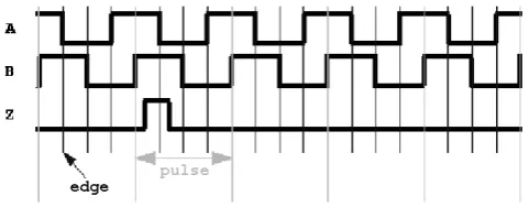
[image:1.595.305.546.319.413.2]Standard encoders produce 3 signals, A, B and Z (Fig. 1). Signal Z sends pulse when encoder goes through its zero position. Signals A and B are phase shifted to each other for detection of direction and represent change of the angle. Number of pulses per revolution makes resolution of an encoder. This number varies but typically is between 60 to 90.000 pulses per revolution. These signals can be sinusoidal (analog) or rectangular (digital). In this paper, we focus only on encoders with digital output signals.
Fig. 1: Rectangular pulses generated by encoder.
A device called DMU was developed in VUTS Liberec which implements upper mentioned method and enables precise dynamic measurement of angular quantities. Because of high demand on measurements we decided to create also version of the DMU that can be easily used inside testing stands and devices for our customers. With regard to currently used application development software platform we decided to use products of company National Instruments (further mentioned only as NI). DMU uses in its last version field-programmable gate array (FPGA) and this influences our options.
Platforms that could be used for implementation of method of measurement with encoders are described in section II. Section III contains information about the design of created software. Section IV has some more detailed information about the software implementation. Section V shows two examples of measurement that were done with developed application created with use of implemented software.
II. HARDWARE OPTIONS
NI has several platforms that could be used for new version of DMU. Their names are PXI, Compact RIO and Single Board RIO. All platforms are able to use FPGA and several types of inputs/outputs.
automation and as laboratory equipment. For implementation with this platform we would need chassis with at least two cards, one with FPGA and one with digital I/O. This platform can use Windows or NI RT Linux as its operating system.
Compact RIO (Compact Reconfigurable Input/Output) [7] is embedded platform aimed for use in industrial environ-ment. Chassis is equipped with ARM or Intel processor and FPGA and it is made to be suitable for most industrial environments. This platform is ideal for cases where we dont need high level of integration into a more complex system. This platform is limited only to NI RT Linux operating system.
Single board RIO [8] is part of Compact RIO platform. It has form of single board instead of fixed chassis and it should be used for low level of integration into complex systems. It has ARM processor and onboard FPGA and it uses NI RT Linux as operating system.
Programming for all these platforms is done in LabVIEW development environment that utilizes G language from NI. We can program FPGA in LabVIEW instead of HDL so its much easier to create application without deep knowledge of HDL.
III. SOFTWARE DESIGN
[image:2.595.322.530.92.227.2]Design of the software was influenced by possible har-dware options. PXI is working as standalone system so it needs only two software layers (FPGA and Host). Com-pactRIO and single-board RIO can use two or three software layers based on requirements of application (communication through Windows client). Software division into three parts was based on already mentioned possible layers (FPGA, Host and Windows).
Figure 2 shows abstraction of software architecture in case of Compact RIO usage. Most of the work is done on FPGA that reads inputs, computes kinematic values and communicates with Host. The Host works as interface for configuring FPGA code and helps to read and transform data from FPGA. Host code can be used on RT or Windows OS. Part which transforms data into real kinematic quantities isnt restricted only to the Host but can be used also as part of Windows remote client. Code that is only for Windows remote client contains mainly communication with the Host. FPGA Library contains many visual instruments (VI; LabVIEW designation for program) that are necessary not only for computing of kinematic values but also for commu-nication with the Host code. An object oriented programming (OOP) usage was limited so that it showed up unusable. Decision was to omit OOP and use procedural programming for this layer. Code on FPGA cant be dynamic because all cases must be known during compilation. That is not possible with dynamic code where we dont know exact number of iterations or others, for example unknown number of for cycle iterations. Example of possible FPGA main code architecture is shown in figure 3. This diagram shows how communication between different parts of code is provided and which resources are used. Code utilizes most of available types of FPGA resources (memory, register and FIFO First In First Out queue). Direct Memory Access FIFO (DMA FIFO) is necessary to use for transfer of information and data between FPGA and the Host. LabVIEW FPGA uses
[image:2.595.304.549.279.385.2]three types of DMA FIFO but our code should use only two, Host-To-Target and Target-To-Host.
Fig. 2: Abstraction of architecture which utilizes Compact RIO and uses Windows remote client.
Fig. 3: Architecture of FPGA application created for ExampleApp.
(a) DMU class
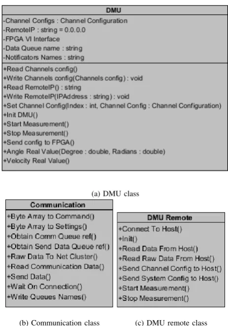
[image:2.595.309.541.430.761.2]Host Library is determined for communication with FPGA (read data and set configuration) and transformation from values that are computed in FPGA. Most of the code was integrated into DMU class (figure 4a) but some part were meant even for use outside of DMU class, e.g. calculation of real values from FPGA values. Communication from the Host to the remote client is provided by Communication class (figure 4b). Communication is done over TCP/IP with protocol that contains few types of packets. Communication is designed as bidirectional with settings coming from remote client (figure 5) and data from DMU class. Part intended for Windows remote client is integrated into DMU Remote class (figure 4c).
0 7 8 15 16 23 24 31
Enable channel Enabled
association
Associate with
channel Type
Number of pulses per rotation Angular Base Decimation
Direction Zeroing Measurement over n-pulses
Moving average over n-values
Number of
counters Measurement over k-pulses
Type of average velocity
[image:3.595.55.284.217.316.2]Measurement over n-pulses (acceleration)
Fig. 5: Structure of configuration for channel that is send between Host and remote client. This structure is based on data type that is used by Host.
IV. IMPLEMENTATION DETAILS
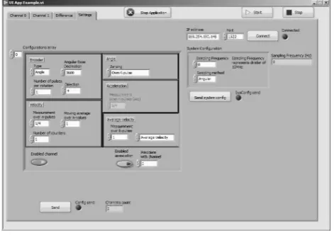
[image:3.595.52.288.448.614.2]An example application (figure 6) was created based on our design of software. NI Compact RIO 9034 with two C modules 9402 (each module has four high-speed LVTTL I/O) was used as hardware platform, so the example application utilizes all three layers mentioned in Section IV.
Fig. 6: GUI of Example application that has been made for testing purposes. Tab with channels configuration and sampling base configuration is selected.
Code of engine for FPGA is divided into distinctive parts, inputs reading, kinematic values calculation, control and data transfer. The most crucial for correct calculation of kinematic values is precise reading of encoders inputs. For this we use single-cycle timed loops (SCTL; more information in [9]) to ensure we get resolution that corresponds with set frequency. For example, frequency 100MHz used by last version of DMU means we got 10ns time resolution. If we want to read from more than one channel, the FPGA code, except control and data transfer, should be copied. This is achieved by modularity of code. We are able to achieve maximal
frequency of 120MHz (time resolution approx. 8.3ns) with created code.
Inside SCTL loop (inputs reading) we detect edges of signals from encoder mentioned in Section I, A, B, and Z. Edge on signal events are detected and timestamp represented by unsigned 32 bit integer is catched. During these events a detection of rotation direction is also made in SCTL. This is crucial during calculation of kinematic values where the direction and the timestamp of arrived edge are used. Status of Z signal is another information that we get from inputs reading. Z signal represents zero position of encoder and in application can cause reset of angle value. Two values of Z signal are processed, one for basic Z pulse detection and second that helps to detect problems with signal noise. These information are part of cluster that is send through FIFO and read by calculation loop.
We need three VI for each channel inside calculation loop, reading of channel configuration related to calculation made inside another VI, recalculation of kinematic values to integer and setting these data to memory. This loop also provides information necessary for sampling of measured data and can be used also for sampling of other data (another quantities measured synchronically). Calculated data are then send by transfer data loop, which transforms them and adds another data used mainly for debugging when sampling signal arrives.
The Host reads data from FPGA and converts them into real kinematic values with usage of DMU class. These data are send towards remote Windows client with help of Communication class in case of the Example App. The Client is connected via Ethernet to the Compact RIO and it is able to receive them and show them in graph in UIExampleApp VI (figure 6) with usage of DMU Remote class.
V. VALIDATION MEASUREMENTS
Two typical examples of the measurement were used for validation of the method. The first task was measurement of physical pendulum. An encoder Heidenhain ROD 260 (18.000 pulses per rotation) was used and the pendulum was connected directly to its shaft. The pendulum movement represents typical example of movement with change of direction. This specific type of movement creates sinusoidal velocity curve. When we used time-based sampling, a graph of angle has also sinusoidal form (figure 7).
[image:3.595.314.537.595.745.2]In addition, the measurement with angular sampling base was done for testing purposes. This type of sampling is typically not suitable for the pendulum measurement but can show how different sampling base can change shape of signal and that our device is able to measure with different sampling base. From figure 8 is evident that the angle curve has a form of triangle. The velocity curves on these diagrams also shows difference between time-based and angular-based measurement.
Fig. 8: Detail of pendulum movement measured with angular sampling base. Change in shape of angle and velocity is due difference between types of sampling bases.
[image:4.595.46.291.177.338.2]The second task was measurement of motor Siemens 1LA7070-0AA10-Z (3x220V) with silicon hose joined that simulated soft torsional shaft. Silicon hose was connected to shaft of a motor as seen on figure 9. Used encoders were (1) Heidenhain ROD 1020 with 3.600 pulses per revolution and (2) Heidenhain ROD 1020 with 1.024 pulses per revolution. This proved that we can use encoders with different pulses per revolution. Our experiment used frequency converter with possibility of velocity setting by potentiometer. Velocity captured during whole measurement from both encoders is shown on figure 10. Difference of angle and velocity between encoders was changing with rise of velocity of a motor (figure 11). This difference was caused by torque oscillations that had occurred due to torsional shaft. But the most significant part of the signal, where we can found torque oscillations caused by flexibility of the torsional shaft, was point of the motor stopping (figure 12).
[image:4.595.306.550.281.435.2]Fig. 9: Motor that we measuremed with two encoders where (1) is connected shaft of motor and (2) is connected to silicon hose used for purpose of simulated soft torsional shaft.
Fig. 10: Progress of velocity on two channels (soft torsional shaft and motor shaft)
Fig. 11: Difference between angle and velocity of two encoders. We can see that when compare graph with figure 10 then with there occurs at one moment during rise of motors velocity a fall of difference. This is due to settling of soft torsional shaft in measured velocity.
Fig. 12: Progress of measurement of velocity on encoders and its difference during shutdown of motor. From this we can clearly see torque osccillation that occurs during this event.
VI. CONCLUSIONS
[image:4.595.302.549.506.677.2] [image:4.595.46.291.613.747.2]different layers of hardware for measurement (FPGA, Host) and software that is responsible for control of measurement hardware (remote client on Windows) were created for this application. Function of the device was tested by two typical examples of the measurement and give comparison to previous version of the device DMU. These tests proved that developed device is able to work as possible replacement. Intended purpose of integration of the device inside complex measurement stands is achievable due to modular structure of our code and also modular hardware platforms from NI. Thanks to FPGA we are able to achieve resolution of measurement approximately 8.3ns due to internal frequency of FPGA code (120MHz).
Further development could be focused on use of encoders with sinusoidal signals and creation of C series modules with connectors compatible with standard industrial encoders.
ACKNOWLEDGEMENT
This work was supported by the Czech Ministry of Edu-cation, Youth and Sports, project LO 1213.
REFERENCES
[1] A. Brandt, T. Lag¨o, K. Ahlin, and J. Tuma, “Main principles and limi-tations of current order tracking methods,”Sound&Vibration, vol. 39, no. 3, pp. 19–22, 2005.
[2] J. Tuma, “Principle and Software for Machine-shaft Angular-vibration Measurements,”Colloquium Dynamics Of Machines, Prague, 2005. [3] V. Cejka, P. Sidlof, and M. Vaclavik, “Method for evaluation of
behavior of mechanisms and gears using angular-based measurements,”
6. Kolloquium Getriebetechnik: Aachen 2005, pp. 101–113, 2005. [4] “PXI Architecture,” http://www.pxisa.org/About/Architecture/Default.
aspx, accessed: 2018-03-02.
[5] National Instruments, “What Is PXI?” http://www.ni.com/pxi/whatis/, Accessed: 2018-03-02.
[6] PICMG Consorcium, “CompactPCI Overview,” https://www.picmg.org/ openstandards/compactpci/, Accessed: 2018-03-02.
[7] National Instruments, “What Is the CompactRIO Platform?” http:// www.ni.com/compactrio/whatis/, Accessed: 2018-03-02.
[8] ——, “Product Flyer - CompactRIO Single-Board Controllers,” http://www.ni.com/pdf/product-flyers/compactrio-single-board-controllers.pdf, Accessed: 2018-03-02.