Abstract—This paper proposes a highly optimized S-box of SM4 algorithm for low-area and high-speed embedded application. A novel methodology is adopted for S-box implementation based on Composite Field Arithmetic (CFA) and mixed basis. The optimization result shows that the S-box based on mixed basis has shorter critical path than S-boxes based on normal basis and polynomial basis. Compared with previous works, the mixed basis based S-box proposed in this paper can achieve the shortest critical path. Besides, the operations over GF((22)2) and the constant matrix multiplications are optimized by Delay-Aware Common Sub-expression Elimination (DACSE) algorithm. ASIC implementation using static 180 nm @ 1.8 V yield an area reduction of 35.57% as compared to direct implementation.
Index Terms—SM4 algorithm, S-box, Composite Field Arithmetic (CFA), mixed basis
I. INTRODUCTION
M4 algorithm is a group symmetric cipher algorithm announced by Chinese government in January 2006 and it has been widely used in various fields of information security, such as wireless local area network (WLAN), Wireless LAN Authentication and Privacy Infrastructure (WAPI), storage device and the smart card system [1]-[2]. As the SM4 algorithm is mostly used in high-speed and resource- constrained applications, it is very necessary to design and implement short-delay and compact circuit of SM4. The implementation of S-box is the most expensive part in terms of the required hardware. Therefore, the short-delay and compact S-box is the key component of the SM4 algorithm.
The design and optimization of SM4 S-box have been studied in detail. The S-box implemented with LUT achieves high throughput but acquires large area. In [3], the N-dimensional hypercube method was introduced to construct S-box. Although the method reduced the area, it is difficult to implement in hardware because of complex
Manuscript received July 03, 2017; revised July 24, 2017. This work was supported in part by the National Natural Science Foundation of China (61376025), the Fundamental Research Funds for the Central Universities (NS2017023) and the Natural Science Foundation of Jiangsu Province (BK20160806).
Y. Zhu is with College of Electronic and Information Engineering, Nanjing University of Aeronautics and Astronautics, Nanjing, 211100, China (e-mail: zhuyuan93@ qq.com).
F. Zhou is with the College of Electronic and Information Engineering, Nanjing University of Aeronautics and Astronautics, Nanjing, 211100, China(e-mail: [email protected]).
N. Wu is with the College of Electronic and Information Engineering, Nanjing University of Aeronautics and Astronautics, Nanjing, 211100, China.
Yasir is with the College of Electronic and Information Engineering, Nanjing University of Aeronautics and Astronautics, Nanjing, 211100, China.
derivation process. In [4]-[5], S-boxes based on polynomial basis and normal basis were introduced. Their optimizations for S-box focused on the hardware overhead at the cost of throughput. Therefore, when the SM4 algorithm is used for high-throughput and area-constrained devices, a short-delay and compact S-box is required for SM4 hardware implementation.
This study focuses on the optimization of S-box for SM4 and the major contributions include:
Coalescence design and implementation based on CFA technology [6] and mixed basis [7].
The MI over GF((2)2)2 and constant matrix multiplications are optimized by DACSE algorithm [8].
II. BACKGROUND OF SM4S-BOX ON CFA
The algebraic expression is shown as (1) and properties of the S-box for SM4 algorithm has been analyzed in [9].
S x( )I x A C A C
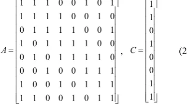
(1) where I is the MI over GF(28). A is the affine matrix and C is row vector. x is the input of S-box and S(x) is the corresponding output. The S-box function involves a pre-affine transformation, MI over GF(28) and a post-affine transformation. A and Care shown in (2).1 1 1 0 0 1 0 1
1 1 1 1 0 0 1 0
0 1 1 1 1 0 0 1
1 0 1 1 1 1 0 0
0 1 0 1 1 1 1 0
0 0 1 0 0 1 1 1
1 0 0 1 0 1 1 1
1 1 0 0 1 0 1 1
A
, 1 1 0 1 0 0 1 1 C
(2)
Since direct calculation of the MI over GF(28) is a complicated and difficult task, we adopt the CFA to reduce the hardware complexity by mapping the MI over GF(28) into composite field GF(((22)2)2).
In CFA technology, an isomorphic mapping matrix is demanded to map the input vector from the finite field GF(28) to the composite field GF(((22)2)2), and its inverse matrix is required to revert the computing results to GF(28). So the S-box based on CFA technique can be expressed as:
1
( )
S x T I x A C T A C (3)
where T is the isomorphic mapping matrix and T-1 is inverse matrix of T. Generally, matrixT-1 and matrix A are merged into a single matrix to reduce the hardware resources. The
S-box Optimization for SM4 Algorithm
Yuan Zhu, Fang Zhou, Ning Wu, Yasir
S
X T× MI over
GF(((22)2)2) AT
-1× Y
[image:1.595.351.545.446.555.2]A× +C +C
architecture of the S-box using the CFA technique is shown in Fig. 1.
III. SUB-OPERATIONS OVER GF(28) IN MI
In CFA technology, the MI over GF(2)8 is built iteratively from GF(2) by using the following irreducible polynomials:
2 28 2 2 2
2
2 2 2
2 2
2 2 : ( = )
2 2 :
2 2 : = + +1
GF GF g v v
GF GF f
GF GF e
(4)
The coefficients {v=(0100)2, λ=(10)2} are used in this paper.
A. MI in Composite Domain
According to the first irreducible polynomial in (4), the MI over GF(28) is decomposed into GF(((22)2)2) as (5).
-1-1 16 16
1 2
16 2 2 16 16
1 2 = = = =
l h l h h l
l h l h l l h
l h
A AA A
a a a a a a
a a a a v a a a
b b B
(5)
where A can be expressed as A=alγ+ahγ16, al, ah ∈GF((22)2). B can be represented as B=bl+bhγ, bl, bh ∈GF((22)2). The
architecture of MI over GF(((22)2)2) is shown in Fig. 2.
As shown in Fig. 2, the MI over GF(((22)2)2) includes two additions, a MI, a square, a constant multiplication and three multiplications. All of the operations are over GF((22)2). The addition over GF((22)2) is defined as bitwise XOR gates. The square and constant multiplication over GF((22)2) can be deduced from multiplication over GF((22)2), and they are usually joint into a single block to reduce the number of gates.
There are two kind multiplications in this paper, mixed multiplication and general multiplication. In mixed multiplication operation, the input and output are represented by polynomial basis and normal basis, respectively. And for the general multiplication operation, the input and output are all denoted by polynomial basis.
Derivations of these operations are described in the following sections.
a)MI over GF((22)2)
In GF((22)2) domain, the input of the MI is denoted by the normal basis {β, β4} and the output is represented by the polynomial basis {1,β}. Its inverse B = A-1 is calculated in (6)
and architecture of MI is shown in Fig. 3.
11 4 4
1
4 4 4
1 2 =
=
=
l h h l h l
l h l h l h l
l h
A AA A
a a a a a a
a a a a a a a
b b B
(6)
Where A can be expressed as A=alβ+ahβ4, al,ah∈GF(22). B
can be represented as B=bl+bhβ, bl, bh ∈GF(22). By using the
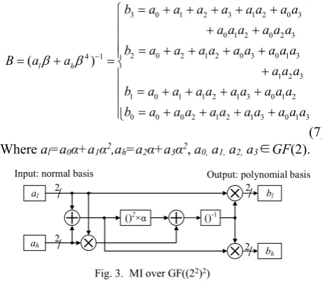
third irreducible polynomial in (4), the MI over GF((22)2) is further decomposed into GF((2)2) as (7).
3 0 1 2 3 1 2 0 3
0 1 2 0 2 3
2 0 2 1 2 0 3 0 1 3
1
1 2 3
1 0 1 1 2 1 3 0 1 2
0 0 0 2 1 2 1 3
4
0 1 3
( l h )
b a a a a a a a a
a a a a a a
b a a a a a a a
a a a a
B
a a a
b a a a a a a a a a
b a a a a a a a a a a
(7) Where al=a0α+a1α2,ah=a2α+a3α2, a0, a1, a2, a3∈GF(2).
The MI over GF((22)2) is optimized by the DACSE algorithm, and the optimized result includes 13 XOR gates and 8 AND gates, which needs 51 equivalent gates, with a reduction of 44.26% in terms of the total area occupancy compared with the direct implementation.
b)Constant Multiplied by Square over GF((22)2)
The input and output of constant multiplied by square operation are denoted by the polynomial basis {1, β} and normal basis {β, β4}, respectively. Constant multiplied by square is calculated as (8) and its architecture is mentioned in Fig. 4.
2 2 2
2 2 2 2
2 2 2 2 4
2 2 2 2 4
4 = ( ) ( ) ( ) = l h l h l h
l h h
l h
A v a a
a a
a a
a a a
b b B
(8)
where A can be expressed as A=al+ahβ, al,ah∈GF(22). B can
be represented as B=blβ+bhβ4, bl, bh ∈GF(22). The constant
multiplied by square p = a2v is further decomposed into GF((2)2) as (9), using the third irreducible polynomial in (4).
3 2
2 3
2
1 0 1 2 3
0 0 2
( l h )
p a
p a
p a a
p a a a a
p a a
(9)
where al=a0α+a1α2,ah=a2α+a3α2, a0, a1, a2, a3∈GF(2).
al 4
ah
()2×υ ()-1
bl
bh 4 4
4
Input: normal basis Output: polynomial basis
[image:2.595.315.546.178.384.2]N N P P P N P P
Fig. 2. MI over GF(((22)2)2)
al 2
ah
()2×α ()-1
bl
bh 2 2
2
Input: normal basis Output: polynomial basis
[image:2.595.51.282.404.490.2]The optimized result consumes 3XOR gates with an area reduction of 25% compared with the direct implementation.
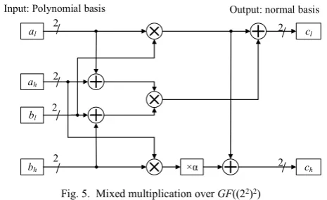
c)Mixed Multiplication over GF((22)2)
Mixed multiplication operation needs a non–zero input represented with the polynomial basis {1, β} and its output is expressed by normal basis {β, β4}. Mixed multiplication
4 ˆ M
shown in Fig. 5 is calculated as (10).
4
4
4
ˆ
=
=
= . l h l h
l h l h h h l l h h
l h
M AB
a a b b
a a b b a b a b a b
c c C
(10)
where A can be expressed as A=al+ahβ, al,ah∈GF(22). B can
be represented in the same way. C can be represented as
C=clβ+chβ4, cl, ch ∈GF(22). By using the third irreducible
polynomial in (4), mixed multiplication C=AB is further decomposed into GF((2)2) as (11).
3 1 0 0 1 2 3 3 2 3 3 0 0
2 1 0 0 1 3 3 2 2 1 1
1 1 0 0 1 2 0 0 2 3 0 0 3
2 1 1 2 3 3 2 2 0 0
0 1 0 0 1 3 0 0 3 2 1 1 2
3 1 1 3 2 3 3 2 2 2 1 1
c a b a b a b a b a b a b
c a b a b a b a b a b
c a b a b a b a b a b a b
C AB
a b a b a b a b a b
c a b a b a b a b a b a b
a b a b a b a b a b a b
(11) where al=a0α+a1α2,ah=a2α+a3α2, bl=b0α+b1α2, bh=b2α+b3α2, a0, a1, a2, a3, b0, b1, b2, b3∈GF(2).
DACSE algorithm is adopted to optimize the mixed multiplication over GF((22)2), and the optimized circuit requires 81 equivalent gates. Compared with the direct implementation, which needs 21 XOR gates and 27 AND gates, it makes 61.5(43.16%) gates reduction in total area cost.
d)General Multiplication over GF((22)2)
The input and output of general multiplication are all denoted by the polynomial basis {1, β}. General
multiplication M4 which is constructed as Fig. 6 is calculated in (12).
4 =
=
{( )( ) }
= . l h l h
l l h h h h l h h l
l l h h l h l h l l
l h
M AB
a a b b
a b a b a b a b a b
a b a b a a b b a b
c c C
(12)
where A can be expressed as A=al+ahβ, al,ah∈GF(22). B and C can be represented in the same way. By using the third irreducible polynomial in (4), general multiplication C=AB is further decomposed into GF((2)2) as (13).
3 2 0 0 2 3 0 0 3 2 1 1 2
2 3 3 2 2 2
2 3 0 0 3 2 1 1 2 3 1 1 3
2 3 3 2 3 3
1 1 0 0 1 2 3 3 2 3 3 0 0
0 1 0 0 1 3 3 2 2 1 1
c a b a b a b a b a b a b
a b a b a b
c a b a b a b a b a b a b
C AB
a b a b a b
c a b a b a b a b a b a b
c a b a b a b a b a b
(13) where al=a0α+a1α2,ah=a2α+a3α2, bl=b0α+b1α2, bh=b2α+b3α2, a0, a1, a2, a3, b0, b1, b2, b3∈GF(2).
The general multiplication optimized by DACSE occupies 75 equivalent gates, with a reduction of 33.33% as compared with the direct implementation.
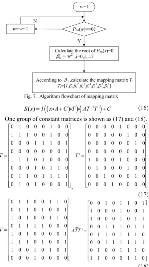
B. Calculation for Mapping Matrix
The calculation procedure of the mapping matrix is shown in Fig. 7 and specific steps are described as follows:
1)Determine the irreducible polynomial coefficients υ and find the minimum root w of P28(w)=0.
2)Calculate other seven roots from the smallest root β0=w in accordance with (14).
3)Generate a mapping matrix Ti according to (15). 2
0 , (i 0 ~ 7 )
i
i
(14)
2 3 4 5 6 7
1, , , , , , ,
i i i i i i i i
T (15)
The mapping matrix T can be calculated only when operations over GF(((22)2)2), GF((22)2) and GF(22) are represented by normal basis, polynomial basis and normal basis, respectively. Since the output of MI over GF(((22)2)2) based on mixed basis is expressed by polynomial basis, it is necessary to convert polynomial basis into normal basis. Therefore, we need to multiply the matrix T' before performing the post-affine operation. So (3) is converted to (16).
al
ah 2
2
Input: polynomial basis Output: polynomial basis
bl
bh
cl
ch 2
×α
2 2
[image:3.595.60.278.58.133.2]2
Fig. 6. General multiplication over GF((22)2)
al
2
ah
()2 bl
bh
2
2
Input: polynomial basis Output: normal basis
()2
×α2
[image:3.595.314.537.339.474.2]2
Fig. 4. Constant multiplied by square over GF((22)2)
al
ah 2
2
Input: Polynomial basis Output: normal basis
bl
bh
cl
ch 2
2 ×α
2
2
[image:3.595.56.289.507.649.2]
1
( ) '
S x I x A C T AT T C (16)
One group of constant matrices is shown as (17) and (18). 0 1 0 0 0 1 0 0
1 1 1 0 0 1 0 0 0 0 0 1 1 1 0 1 0 0 0 0 0 0 0 1 1 1 1 0 1 0 0 0 0 0 0 1 0 1 1 0 0 1 1 0 1 1 1 1 0 1 0 1 0 0 0 1 T
,
0 0 0 0 1 0 0 0 0 0 0 0 0 1 0 0 0 0 0 0 0 0 1 0 0 0 0 0 0 0 0 1 '
1 0 0 0 1 0 0 0 0 1 0 0 0 1 0 0 0 0 1 0 0 0 1 0 0 0 0 1 0 0 0 0 T
(17)
0 1 1 0 0 1 1 0
0 1 1 0 1 0 0 1
1 0 1 0 0 1 1 0
0 1 1 1 1 0 0 0
1 0 1 0 0 0 0 1
1 1 1 0 1 0 0 1
1 0 0 1 0 1 0 1
0 0 0 1 0 0 0 0
T
0 0 1 0 1 1 0 1
1 0 0 0 1 0 0 1
1 0 0 0 1 0 1 1
0 0 1 1 1 0 1 1
'
0 1 1 0 1 1 1 0
0 0 1 1 1 1 1 1
0 1 0 0 1 1 1 0
1 1 0 0 0 1 1 0
ATT
(18)
Optimized by DACSE algorithm, the required hardware resources for optimized matrices are 58 XOR gates, with an area reduction of 34.09% compared with the direct implementation.
IV. IMPLEMENT RESULTS AND ANALYSIS
In this paper, the S-box for SM4 algorithm is designed by CFA technology and mixed basis. The critical path of S-box based on different basis are shown in Table I.
In Table I, the implementations of SM4 S-boxes based on polynomial basis and normal basis are realized according to [4] and [5], respectively. From the delay shown in Table I, the optimized S-boxes has been reduced by 22.5% and 17.05% in
the terms of total delay, as compared to S-box based on polynomial basis and normal basis, respectively.
The critical path of MIs over GF(((22)2)2) have a decisive effect on the critical path of whole S-box, because the critical path of mapping matrices of SM4 S-box are 3 XOR gates with no further optimization. Therefore, the comparison of critical path of MI can explain the performance of the whole S-box. Because of the MIs of AES S-box and SM4 S-box over
GF(((22)2)2) have the same structure, their critical path can be compared directly. Comparisons of the critical path between our works and selected previous works are summarized in Table II. Compared with these works, the S-box based on mixed basis in this paper has the shortest critical path.
In order to reduce the area cost of S-box, the designed S-box is optimized by DACSE algorithm. The type and quantity of logic gates as well as the total number of transistors in the direct implementation and optimization by DACSE are listed in Table III, respectively.
TABLEI
THE CRITICAL PATH OF S-BOX IN COMPOSITE DOMAIN Basis Used Construction Critical Path
AND XOR
Polynomial
T× — 3
AT-1× — 3
MI over GF(((22)2)2) 4 17
S-box 4 28
Normal
T× — 3
AT-1× — 3
MI over GF(((22)2)2) 4 15
S-box 4 26
ours
T× — 3
AT-1T’× — 3
MI over GF(((22)2)2) 4 10
S-box 4 21
TABLEII
THE CRITICAL PATH OF MI OVER GF(((22)2)2)
Works Basis Used Critical Path
AND XOR
[10] Polynomial 4 13
[11] Polynomial 4 17
[12] case I Polynomial 4 14
[13] Polynomial 4 14
[12] case II Normal 4 12
[14] Normal 4 14
[15] Normal 4 14
[16] Normal 3 14
[7] Mixed
Mixed
4 14
ours 4 10
TABLEIII
THE AREA COST AND CRITICAL PATH BY EACH PART OF THE CFA-BASED S-BOX
Module Direct Optimized by DACSE
AND XOR Gates Critical Path AND XOR Gates(Reduction) Critical Path
A —— 32 96 3 TXOR —— 21 63(34.38%) 3 TXOR
T —— 19 57 3 TXOR —— 14 43(26.32%) 3 TXOR
AT-1T’ —— 27 81 3 TXOR —— 13 39(51.85%) 3 TXOR
C —— 10 30 2 TXOR —— 10 30 2 TXOR
MI over
GF(((22)2)2) 114 108 495 10 TXOR+4 TAND 50 80 315(36.36%) 10 TXOR+4 TAND
s-box 114 196 759 21 TXOR+4 TAND 50 138 489(35.57%) 21 TXOR+4 TAND
P28(w)==0? N
Y
w=1
Calculate the root of P28(x)=0 ,i=0,1,...7
w=w+1
According to βi ,calculate the mapping matrix Ti
[image:4.595.49.291.52.483.2]Ti=[1,βi,βi2,βi3,βi4,βi5,βi6,βi7]
[image:4.595.65.533.673.778.2]In Table III, TXOR and TAND denote the delays of XOR gates and AND gates, respectively. As shown in Table III, the optimized circuit of MI over GF(((22)2)2) is reduced by 36.36%. The area reduction for S-box is up to 35.57%.
V. CONCLUSIONS
This paper proposed a highly optimized S-box based on CFA and mixed basis for SM4 algorithm. Compared with S-boxes based on polynomial basis and normal basis, the proposed S-box has shortest critical path of 21 XOR gates and 4 AND gates. The MI over GF(((22)2)2) has the shortest delay compared with previous works that based on the normal basis, polynomial basis or mixed basis. Besides, the designed S-box was optimized by DACSE algorithm to reduce the area cost. As compared to the direct implementation, the area reduction of MI over GF(((22)2)2) and the optimized S-box are up to 36.36% and 35.57% using 180 nm 1.8 V COMS technology.
REFERENCES
[1] W. Diffie and G. Ledin. “SMS4 Encryption Algorithm for Wireless Networks,” Iacr Cryptology Eprint Archive, 2008.
[2] Office of State Commercial Cipher Administration. (2006). SMS4 cipher for WLAN products. [Online]. Available: http://www.oscca.gov.cn/UpFile/200621016423197990.pdf [3] Y. Wang, L. I. Shu-Guo and T. University. “The Application of
Hypercube Method in S Box of SM4,” Microelectronics & Computer, vol. 31, no. 7, pp. 10–17, Jul. 2014.
[4] H. Liang, L. Wu and X. Zhang. “Design and implementation of SM4 block cipher based on composite field,” Microelectronics & Computer. vol. 32, no. 5, pp. 16–20, May. 2015.
[5] Y. H. Xu, X. F. Bai and L. Guo. “A new algorithm of S-box for hardware implementation of SMS4,” Journal of University of Science & Technology of China. vol. 39, no. 11, pp. 1164–1170, Nov. 2009. [6] Y. Chen, X. Zou, Z. Liu, Y. Han and Z. Zheng. “Energy-efficient and
security-optimized AES hardware design for ubiquitous computing,”
Journal of System Engineering and Electronic, vol. 17, no. 4, pp. 652–658, 2008.
[7] Y. Nogami, K. Nekado, T. Toyota, N. Hongo and Y. Morikaw, “Mixed bases for efficient inversion in F(((2)2)2)2 and conversion matrices of
SubBytes of AES,” IEICE Transactions on Fundamentals of Electronics Communications & Computer Sciences, vol. 97, no. 6, pp. 1318–1327, 2010.
[8] X. Zhang, X. Wu, F. Zhou and X. Chen, “An optimized delay-aware common subexpression elimination algorithm for hardware implementation of binary-field linear transform,” IEICE Electronics Express, vol. 11, no. 22, pp. 20140934–20140934, 2014.
[9] F Liu, W. Ji, L. Hu, J. Ding, S. Lv and A. Pyshkin, et al, “ Analysis of the SMS4 Block Cipher,” Information Security and Privacy, Australasian Conference, vol. 4586, pp. 158–170, Jul.2007. [10] X. Zhang and K. K. Parhi, “On the Optimum Constructions of
Composite Field for the AES Algorithm,” IEEE Transactions on Circuits & Systems II Express Briefs, vol. 53, no. 10, pp. 1153-1157,2006.
[11] N. Mentens, L. Batinan, B. Preneeland, and I. Verbauwhede, “A systematic evaluation of compact hardware implementations for the Rijndael S-box,” Cryptographers’ Track at the RSA Conference. Springer Berlin Heidelberg, vol. 3376, pp. 323-333, 2005.
[12] X. Zhang, N. Wu, G. Yan and L. Dong, “Hardware implementation of compact AES S-box,” Iaeng International Journal of Computer Science, vol. 42, no. 2,pp. 125-131, 2015.
[13] D. Canright, “A very compact Rijndael S-box,” Technical Report Collection, pp.4-5, 2005.
[14] M. M. Wong, M. L. D. Wong, A.K. Nandi and I. Hijazin, “Composite field GF(((22)2)2) Advanced Encryption Standard (AES) S-box with
algebraic normal form representation in the subfield inversion,” Circuits Devices & Systems let, vol. 5, no. 6, pp. 471-476, 2011. [15] M. M. Wong, M. L. D. Wong, A. K. Nandi and I. Hijazin,
“Construction of Optimum Composite Field Architecture for Compact