Abstract— This paper presents an efficient algorithm for measuring ranges between multiple UWB (Ultra Wide Band) transceivers. UWB device provides TOF (Time Of Flight) information of communication packet that can be converted to distance. For this reason, it is considered as a potential tool for estimating position of an object in indoor environment where GPS cannot be used. As a general method, range data between two UWB transceivers is computed with the time for round trip of communication packet because they have different time references respectively. However, it becomes a time consuming process in case of ranging between multiple transceivers. The proposed method solves the problem and saves processing time by employing broadcast in communication protocol from tag to multiple anchors. In addition, it is applied to a mobile robot system to estimate the location of moving target to follow.
Index Terms— Mobile Robot, Target tracking, Position Estimation, UWB radio communication
I. INTRODUCTION
or various robotic applications, the technology to obtain exact position of an object is considered as an important issue. Generally, sensor devices exploiting optical measurement such as laser range finder, camera and GPS have been mainly used for recognizing and tracking the position of an object. Laser range finder and camera can provide the position of an object by recognition algorithms [1]. However, it has some problems such as weakness to occlusion by other objects, computation burden of complex image processing, and so on. Meanwhile, GPS system is a well-known and easy-to-use method for taking position information in outdoor environment [2, 3], thus being adopted especially for navigation of vehicle and drone. However, it cannot be used in indoor environment.
In order to overcome the above problems, many researches utilizing wireless communication such as wifi and bluetooth have been carried out because they can be used in an indoor environment and have merits of being less influenced by obstacles [4]. Recently, UWB (Ultra Wide Band) is considered as a potential solution for positioning system using radio communication because it shows better performance in accuracy (10 [cm] average ranging error
Manuscript received December 11, 2017; revised February 14, 2018. All authors are with Mechanical Engineering Course, Graduate School of Science and Engineering, Ehime University, 3 Bunkyo-cho, Matsuyama 790-8577, Japan.
Oh Seong Park (e-mail: [email protected]) Jae Hoon Lee (e-mail: [email protected]) Shingo Okamoto (e-mail: [email protected])
according to specification) than wifi and bluetooth communication [5, 6]. However, if we adopt the general method of round trip strategy between two transceivers, it becomes time consuming process for the case of communication between multiple devices owing to the reason that the number of communication processes increases according to the number of devices in the network. However, fast iteration with small sampling time is desirable for most applications of position estimation.
Therefore, this paper proposes an efficient algorithm to measure ranges between multiple UWB wireless communication modules [7]. Furthermore, it is applied to a positioning system to estimate the position of a target with filtering technique. Besides, experimental works of target
Position Estimation Method Using Multiple
UWB Radio Communication Modules and Its
Application to Mobile Robot
Oh Seong Park
,
Jae Hoon Lee,
Member, IAENG
, and Shingo Okamoto,
Member, IAENG
[image:1.595.310.546.375.764.2]F
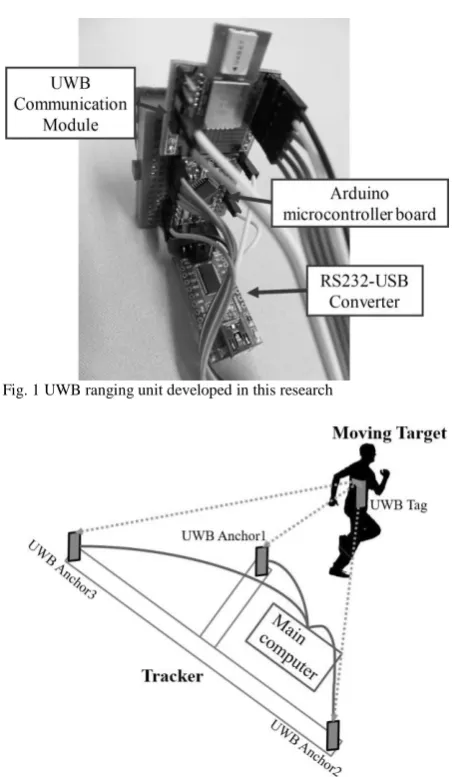
Fig. 1 UWB ranging unit developed in this research
[image:1.595.311.546.385.576.2]tracking were conducted by using a mobile robot system embedded with the proposed algorithm. The estimated position of the target was compared with the actual position which is obtained by LRF (Laser Range Finder).
This paper is organized as follows. In Section II, target positioning system used in this research is introduced. The proposed ranging algorithm between multiple communication modules is explained in Section III. In Section IV, the mobile robot system embedded with the positioning system is addressed, and experimental works using the robot is explained in Section V. Finally, conclusions are given in Section VI.
II. TARGET POSITIONING SYSTEM USING UWB MODULES A. Development of UWB Ranging Unit
Figure 1 shows the ranging unit including UWB module developed in this research. The UWB module is commercially available DWM1000 from DecaWave Co. [8]. An additional microcontroller of Arduino pro mini is used as a processor to manipulate communication data. Communication between main computer and microcontroller is done via RS232-USB converter. The UWB module can be used with data rate from 110[Kbps] to 6.8[Mbps] and pulse repetition rate from 16[MHz] to 64[MHz] [9, 10].
B. Target Positioning System
The positioning system consists of tracker and target parts as shown in Fig. 2. The tracker part consists of three anchor units and a main computer. Three anchor units are connected to the main computer with a USB cable. Each anchor unit can calculate the distance between anchor unit itself and tag unit by using two-way ranging algorithm. The main computer calculates the position of the Tag unit with trilateration in local coordinate [11]. The tag unit plays a role of target, thus it should be attached to a target object for tracking.
III. POSITIONING ALGORITHM BETWEEN UWB MODULES A. Typical Ranging Algorithm between Two UWB Modules
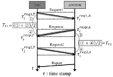
To range using two UWB wireless communication modules, it is necessary to measure the time-of-flight (TOF) which is the time required for the radio signal to travel from the tracker unit to the target unit. However, accurate TOF information cannot be obtained by simple computation because the devices operate with their own time references independently, moreover they are different with each other. Generally accurate TOF is measured by two times of round trip communication between two UWB modules where a message is sent from tag to an anchor and then anchor replies to the tag. The communication algorithm is shown as graphical illustration in Fig. 3 [5, 12].
For computing time only for trip of request and response messages, the time of processing in anchor should be subtracted from the period from sending the message to receiving its response measured at tag. The equation for the computation is given by
𝑇𝐹1= {(𝜏𝑖 𝑟𝑒𝑠𝑝,𝑇
− 𝜏𝑖𝑟𝑒𝑞1,𝑇) − (𝜏𝑖𝑟𝑒𝑠𝑝,𝐴− 𝜏𝑖𝑟𝑒𝑞1,𝐴)} 2⁄ . (1) where 𝜏 denotes the time stamp. The time stamp is registered by all UWB wireless modules when they transmit or receive the messages. The superscripts 𝑟𝑒𝑞1, 𝑟𝑒𝑞2, 𝑟𝑒𝑠𝑝
of 𝜏 denote the type of messages which means Request1, Request2, Response, respectively. Additional superscript 𝑇 and 𝐴 denote the type of unit, i.e., Tag or Anchor, respectively. The subscript 𝑖 of 𝜏 denotes the actual time of ranging process. Thus the first term of equation (1) denotes the time period from the instance of sending a request message to that of receiving its response by Tag unit. The second term denotes the time that is required for the processing by the Anchor unit from the instance of receiving a request message to that of sending its response. Therefore, the round-trip-time of the Tag unit is obtained, and the TOF is computed from it resultantly.
Similarly, the TOF of Anchor unit is given by 𝑇𝐹2= {(𝜏𝑖
𝑟𝑒𝑞2,𝐴
− 𝜏𝑖𝑟𝑒𝑠𝑝,𝐴) − (𝜏𝑖𝑟𝑒𝑞2,𝑇− 𝜏𝑖𝑟𝑒𝑠𝑝,𝑇)} 2⁄ . (2) Finally, the resultant TOF value is computed from the average of two way ranging between Tag and Anchor units as following.
𝑇 = (𝑇𝐹1+ 𝑇𝐹2) 2⁄ . (3)
Accordingly, the range between Tag unit and Anchor unit can be easily computed by multiplication with TOF and a radio velocity constant c (about 0.00469[m/s]) as
[image:2.595.316.540.391.544.2]𝑑 = 𝑐 × 𝑇. (4) The ranging process between Tag and Anchor units is carried out with the frequency of 40 [Hz] in the developed system embedded with the above mentioned algorithm.
Fig. 3 Illustration of typical ranging method between two ranging units
[image:2.595.317.541.570.752.2]B. Efficient Algorithm for Ranging Between Multiple UWB Units
It is necessary to range between a moving Tag unit and fixed multiple Anchor unit for positioning of target using multiple UWB wireless communication modules. However, if we adopt typical method of round trip strategy for communication between multiple devices, there occurs multiple communication events between them, thus it becomes a time consuming process resultantly.
Therefore, this problem causes serious speed down in ranging process as a result. It has been observed that the conventional method shows about 10 Hz in the in our ranging system that has one tag and three anchors. To address this problem, a new ranging algorithm was proposed in this paper. It is possible to save processing time by employing broadcasting method in the communication protocol from tag to multiple anchors. Fig. 4 shows the graphical illustration of processes in the proposed algorithm.
It was assumed that the system has one Tag and three Anchors. The Tag unit sends a request message for all Anchor units as broadcast. Besides, every request message includes the information of time stamps when the Tag sent its request as well as when the responses from all Anchors were received in previous communication. In that case, each Anchor unit is required to send its response message in different time from others because Tag cannot receive multiple messages at the same time. A time delay of 5[ms] between sending responses by Anchor unit was employed in the system. Finally, the Anchor unit performs ranging computation with the previous and current timestamp information. Therefore, the computations in Tag and Anchor units are given as following equations.
𝑇𝐹1,𝑖−1= {(𝜏𝑖−1
𝑟𝑒𝑠𝑝,𝑇,𝐴𝑗
− 𝜏𝑖−1𝑟𝑒𝑞,𝑇) − (𝜏𝑖−1𝑟𝑒𝑠𝑝,𝐴𝑗− 𝜏𝑖−1𝑟𝑒𝑞,𝐴𝑗)} 2⁄ , (5)
𝑇𝐹2,𝑖−1= {(𝜏𝑖
𝑟𝑒𝑞,𝐴𝑗
− 𝜏𝑖−1𝑟𝑒𝑠𝑝,𝐴𝑗) − (𝜏𝑖𝑟𝑒𝑞,𝑇− 𝜏𝑖−1𝑟𝑒𝑠𝑝,𝑇,𝐴𝑗)} 2⁄ . (6) Where j denotes the number of Anchor units. The TOF for round trip of message can be obtained by Anchor units with equation (5) and (6). Then equation of average TOF is given by
𝑇𝑖−1= (𝑇𝐹1,𝑖−1+ 𝑇𝐹2,𝑖−1) 2⁄ . (7)
Finally, the range of each Anchor unit, the distance from each Anchor to the Tag, is computed as following.
𝑑𝑖−1𝐴𝑗 = 𝑐 × 𝑇𝑖−1 (8)
It has been observed that the proposed method is capable to keep about 24 Hz in a UWB communication network having one tag and three anchors, while the conventional method shows about 10 Hz in the same hardware system.
C. Trilateration Algorithm for Target Positioning
The position of the target can be obtained with trilateration algorithm. It is a method of determining location of observation point by measurement of distances, using the geometry of circles, spheres or triangles.
In a 2D space, if the observation point lies on the point of two intersecting circles, knowing the center positions of the circles and their radii, it provides sufficient information to narrow the possible locations down to two. Additional information of the other circle may narrow the possibilities down to one unique location.
Generally, the equation of the circle with two points which are 𝑆𝑖(𝑥1, 𝑦𝑖) and 𝑋(𝑥, 𝑦) is given by
𝑟𝑖2= (𝑥 − 𝑥𝑖)2+ (𝑦 − 𝑦𝑖)2. (9)
In general coordinate system, three circles whose radii become 𝑟1, 𝑟2 and 𝑟3 intersect at 𝑃(𝑥, 𝑦). It can be
represented with following three equations.
𝑟12= (𝑥 − 𝑥1)2+ (𝑦 − 𝑦1)2, (10)
𝑟22= (𝑥 − 𝑥2)2+ (𝑦 − 𝑦2)2, (11)
𝑟32= (𝑥 − 𝑥3)2+ (𝑦 − 𝑦3)2. (12)
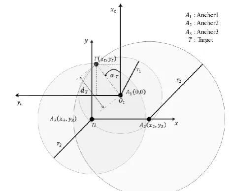
To simplify the problem, three anchor coordinates are defined as,
𝐴1= (𝑥1, 𝑦1), (13)
𝐴2= (𝑥2, 0), (14)
𝐴3= (0, 0). (15)
Where, they are depicted with respect to the coordinate system of 𝑜 − 𝑥̂𝑦̂ in Fig. 5. Then the equations can be rewritten as follows.
𝑟12= (𝑥2− 𝑥12) + (𝑦2− 𝑦12), (16)
𝑟22= (𝑥2− 𝑥22) + 𝑦2, (17)
𝑟32= 𝑥2+ 𝑦2. (18)
Therefore the target position 𝑃(𝑥, 𝑦) can be obtained as 𝑥 =𝑟32−𝑟22+𝑥22
2𝑥2 , (19)
𝑦 =𝑟32−𝑟12+𝑥12+𝑦12−(2𝑥1𝑥)
2𝑦2 . (20) Finally, for target tracking application, the position of target, 𝑃(𝑥𝑡,𝑦𝑡) is represented according to the tracking
coordinate system of 𝑜𝑡− 𝑥̂𝑡𝑦̂𝑡 as follows.
𝑦𝑡= 𝑥2−𝑥3
2 −
𝑟32−𝑟22+(𝑥2−𝑥3)2
2(𝑥2−𝑥3) , (21)
𝑥𝑡=
𝑟32−𝑟12+𝑥22+𝑦22−(2𝑥1(𝑥2−𝑥32 −𝑦𝑡))
2𝑦2 + 𝑦2. (22)
D. Method of Target Position Estimation
The position information measured with UWB modules is easy to have errors due to noise of wireless communication. In order to reduce the error, Kalman filtering with linear motion model that assumes the object moves with constant velocity in a short period was adopted in this research. Where, covariance values of the acceleration in motion model and observation error in measurement are assumed as 1m/s2 and
[image:3.595.49.283.576.770.2]0.5m, respectively.
E. Calibration of UWB Ranging System
The main reasons of error in ranging with UWB module are communication conditions such as directional relationship of antenna of UWB modules and difference of clock frequency of modules, and so on [13]. In particular, difference of module clock frequency causes critical ranging error. UWB wireless communication module measures time with the time stamp measured by the clock frequency embedded in each module. So, the difference between clock frequencies of modules causes time error in measurement. Moreover, it becomes ranging error as a result. For reduction of ranging error, the distance data was calibrated by modifying parameters of relationship between TOF and actual range for each Anchor unit. The correction equation can be obtained from comparison between the actual distance and the ranging result. The actual distance between target and fixed Anchor units was obtained from LRF.
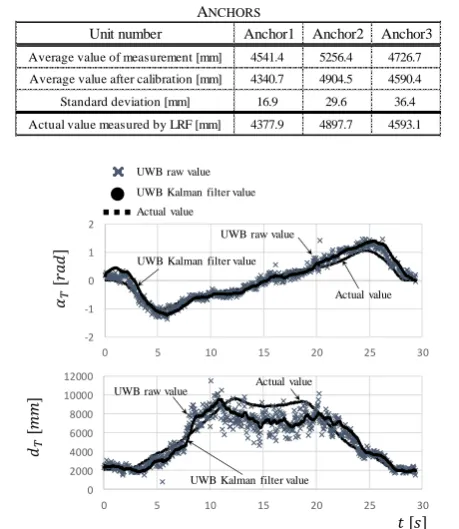
In order to check the effectiveness of calibration, ranging experiment was carried out. The Tag unit was located in front of the anchors. All distance data of Anchor units was corrected in this experiment. Fig. 6 and Table 1 show the result of the experiment.
Ranging error was checked at a point in front of the Anchors. Error values of ranging between tag and all Anchor units before calibration were about 164 [mm], 359 [mm], and 134 [mm], respectively. While that with Anchor units after calibration was reduced, thus resultantly they were about 37 [mm], 7 [mm], 3 [mm], respectively.
F. Target Tracking Experiment
In order to confirm the continuous target tracking performance of a UWB positioning system, experiment of tracking moving human target was carried out.
The human target is moving in front of the robot for 30 seconds according to a trajectory of rectangle. Furthermore, the LRF is used to check the actual position of the human target. In order to check the effectiveness of target tracking with UWB positioning system, the target position estimated with the Kalman filter was compared with the measurement of a LRF.
Fig. 7 shows the trajectory of human target. The dash line denotes the real position of the human target that is observed with a LRF. The cross dots denote position information of the human target which is obtained with UWB wireless communication modules. The circle dots denote the estimated position of the human target with Kalman filter. It was observed that the distance and direction between human target and the UWB positioning system can be estimated well in the experiments.
IV. APPLICATION TO HUMAN FOLLOWING NAVIGATION OF MOBILE ROBOT
[image:4.595.54.276.264.476.2]A. Mobile Robot System
[image:4.595.45.545.273.776.2]Fig. 6 Experimental result of ranging for each Anchors
TABLE I EXPERIMENTAL RESULT OF RANGING FROM TAG TO ANCHORS
Fig. 7 Result of target tracking experiment
Unit number Anchor1 Anchor2 Anchor3
Average value of measurement [mm] 4541.4 5256.4 4726.7 Average value after calibration [mm] 4340.7 4904.5 4590.4
Standard deviation [mm] 16.9 29.6 36.4
Actual value measured by LRF [mm] 4377.9 4897.7 4593.1
-2 -1 0 1 2
0 5 10 15 20 25 30
0 2000 4000 6000 8000 10000 12000
0 5 10 15 20 25 30
UWB raw value UWB Kalman filter value Actual value
𝑠
𝑑𝑇
𝑇
𝑟
𝑑
UWB raw value UWB Kalman filter value
Actual value
UWB raw value
[image:4.595.318.546.411.769.2]UWB Kalman filter value Actual value
Fig. 8 Mobile robot with UWB positioning system (Three Anchors) and LRF
[image:4.595.348.545.477.624.2] [image:4.595.53.283.505.770.2]The mobile robot with UWB ranging system developed in this research is shown in Fig. 8 and its block diagram is given in Fig. 9. It was equipped with a three UWB wireless communication modules for target tracking and a LRF (UTM-30LX, HOKUYO co.) for recognizing objects near the robot. The information from both sensors and the odometer of the robot are processed in the laptop computer installed as main controller. An embedded microcontroller (SH2) was used to control the two rear wheels of the robot. It provides robot’s position by using odometer method the rotation angle of both wheels. A NI-MH battery of 24 [V] was used as embedded power source. The three UWB wireless communication modules operates with USB power source from a laptop computer.
B. Human Following Algorithm
[image:5.595.319.541.260.762.2]For human following motion, the robot is controlled based on the position relationship between the robot and the target. Fig. 10 shows the schematic representation of motion control to follow a target person considering an obstacle. Two inputs to control the mobile robot are the moving speed, 𝑣𝑅, for
linear motion, and the angular rate, 𝜔𝑅, for rotational motion.
The speed should be changed to keep the distance from the robot to the target. Therefore, it should be increased for the instance of long distance, and reduced for the case of short distance. Besides, if the target is near, the robot should not move for avoid collision with him.
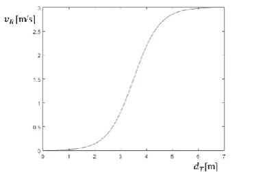
In order to realize the above mentioned motion, a sigmoid function was adopted to generate the robot speed as following.
𝑣𝑅= 𝑉𝑚𝑎𝑥∗
1
1+𝑒−𝐾𝑣∗(𝑑𝑇−𝑑𝑡ℎ). (23)
Where, 𝑑𝑇 represents the distance between the robot and
the target person, 𝑑𝑡ℎ represents the threshold of distance for
the range where the robot does not move, 𝐾𝑣 denotes the
slope of sigmoid function for the relative range between distance and output speed, which plays a role of control gain, finally, 𝑉𝑚𝑎𝑥 is the maximum value of the robot speed,
respectively. The resultant relationship by Eq. (23) is displayed in Fig. 11.
In outdoor environment there could be many obstacles around the robot. Therefore, the robot needs a particular function for safety to be stopped temporarily if the obstacles exist in a certain area near itself. The radius of the safety area is depicted as 𝐷𝑆 in Fig. 8, where 𝑑𝑜 represents the distance
between the robot and the obstacle.
For human following motion, the moving direction of the robot should be aligned to that from the robot itself to the target. So the robot angular velocity is decided based on the direction from the robot to the target person as
𝜔𝑅= 𝐾𝜔 𝑇. (24)
Where, 𝑇 denotes the direction from the robot to the
Fig. 10 Schematic representation of motion control of the robot to follow target
Fig. 11 Velocity variation of the mobile robot based on distance between the robot and the target
(a) t = 3 [s]: The mobile robot follows the moving target
(b) t = 6 [s]: The mobile robot is stopped instantly due to interfering by the obstacle
(c) t = 8 [s]: The mobile robot resumes target following
(d) t = 11 [s]: The mobile robot is stopped according to the motion of the target in safety area
[image:5.595.64.285.448.599.2] [image:5.595.63.257.634.760.2]target person with respect to the local coordinate system, namely the tracking coordinate system. 𝐾𝜔 denotes the
proportional gain. 𝜃𝑅 denotes the orientation of the robot
with respect to the global coordinate system given by odometry.
V. EXPERIMENTAL WORKS
A. Human Following Experiment Method
Human following experiment was conducted to show the effectiveness of the proposed motion control of human following with the developed UWB target tracking system. The target person walks about 14 meters while an obstacle person walked across the front of the robot. Fig. 12 shows the successive scenes of the experiment, captured with a digital camera. The person of orange t-shirt represents the target person with Tag unit and the person of purple t-shirt represents the moving obstacle interfering between the target and the robot.
B. Result of Human Following Experiment
As shown in Fig. 12, the robot could follow the target
person well with keeping the distance, and stop immediately when the obstacle is near itself, resume following motion after his going out the safety area, stop according to the motion of the target resultantly.
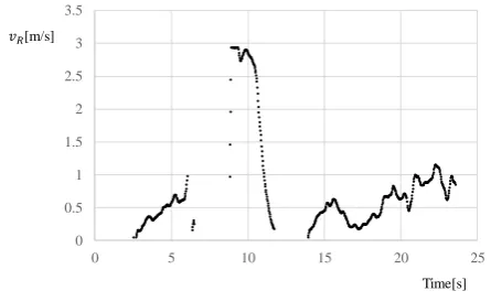
Fig. 13 shows the motion trajectories of the target and the obstacle which are observed with LRF and the robot position measured with odometery. Fig. 14 shows the motion trajectories of the robot and target where the target trajectory is estimated by UWB. Fig. 15 shows the change of robot velocity during the experiment. It was observed that despite the disturbance of the moving obstacle the robot was able to follow the moving human target.
VI. CONCLUSIONS
An efficient algorithm to reduce processing time in ranging using multiple UWB wireless communication modules was proposed in this work. Then it was applied to the positioning system including one Tag and three Anchors developed in this study. In addition, human following experimental works with the system was conducted. As a result, it was confirmed that the mobile robot using UWB target tracking system was able to follow a target moving with speed up to 3 [m/s], and keep tracking well even when the target is occluded by another obstacle.
ACKNOWLEDGMENT
This work was supported in part by NEXCO Group Companies’ Support Fund to Disaster Prevention Measures on Expressways, Japan.
REFERENCES
[1] Y. E. Abdelgabar, J. H. Lee, and S. Okamoto, “Motion control of a three active wheeled mobile robot and collision-free human following Navigation in Outdoor Environment,” Proceedings of IMECS, Vol. 1, pp. 248-253, 2016.
[2] G. M. Hoffmann, H. Huang, S. L. Waslander, and C. J. Tomlin, “Precision flight control for a multi-vehicle quadrotor helicopter testbed,” Control engineering practice, Vol. 19, pp. 1023-1036, 2011. [3] R. Ivanov, “Real-time GPS track simplification algorithm for outdoor navigation of visually impaired,” Journal of Network and Computer
Applications, Vol. 35, pp. 1559-1567, 2012.
[4] Y. B. Bai, “Development of a Wi-Fi and RFID based indoor location and mobility tracking system,” Univ. Royal Melbourne Institute of
Technology, Melbourne, Austria, Doctoral thesis, 2016.
[5] M. W. Mueller, M. Hamer, and R. D’Andrea, “Fusing ultra-wideband range measurements with accelerometers and rate gyroscopes for quadrocopter state estimation,” Proceedings of ICRA, pp. 1730-1736, 2015.
[6] B. Hepp, T. Nageli, and O. Hilliges, “Omni-directional person tracking on a flying robot using occlusion-robust ultra-wideband signals,”
Proceedings of IROS, pp. 189-194, 2016.
[7] O. S. Park, J. H. Lee, and S. Okamoto, “Efficient ranging algorithm using multiple UWB wireless transceivers and its application to position estimation,” Proceedings of AROB, pp. 946-950, 2018. [8] DecaWave, “DWM1000 Datasheet.” [Online]. Available:
http://www.decawave.com
[9] DW1000 User manual, DecaWave Ltd, 2015.
[10] APS006 Application note - Channel effects on communications range and time stamp accuracy, DecaWave Ltd 2015, 2014.
[11] P. Cotera, M. Velazquez, D, Cruz, L. Medina, and M Bandala, “Indoor robot positioning using an enhanced trilateration algorithm,”
International Journal of Advanced Robotic Systems, Vol. 13, 2016.
[12] M. Yavari and B. G. Nickerson, “Ultra wideband wireless positioning systems,” Dept. Faculty Comput. Sci., Univ. New Brunswick,
Fredericton, NB, Canada, Tech. Rep. TR14-230, 2014.
[image:6.595.51.285.317.457.2][13] A. Ledergerber, and R. D’Andrea, “Ultra-wideband range measurement model with gaussian processed,” Proceedings of CCTA, pp. 1929-1934, 2017.
[image:6.595.55.286.477.614.2]Fig. 13 Trajectory of the target (orange points) and the obstacle (purple points) from global coordinate system with LRF
Fig. 14 Trajectory of the target (red points) and the robot (green points) from global coordinate system with UWB and odometry respectively
Fig. 15 Velocity variation of the robot while human following with odometry
0 0.5 1 1.5 2 2.5 3 3.5
0 5 10 15 20 25
[image:6.595.56.279.632.769.2]