NONRESIDENT
TRAINING
COURSE
SEPTEMBER 1998
Navy Electricity and
Electronics Training Series
Module 2—Introduction to
Alternating Current and
Transformers
PREFACE
By enrolling in this self-study course, you have demonstrated a desire to improve yourself and the Navy. Remember, however, this self-study course is only one part of the total Navy training program. Practical experience, schools, selected reading, and your desire to succeed are also necessary to successfully round out a fully meaningful training program.
COURSE OVERVIEW: To introduce the student to the subject of Alternating Current and Transformers who needs such a background in accomplishing daily work and/or in preparing for further study.
THE COURSE: This self-study course is organized into subject matter areas, each containing learning
objectives to help you determine what you should learn along with text and illustrations to help you understand the information. The subject matter reflects day-to-day requirements and experiences of personnel in the rating or skill area. It also reflects guidance provided by Enlisted Community Managers (ECMs) and other senior personnel, technical references, instructions, etc., and either the occupational or naval standards, which are listed in the Manual of Navy Enlisted Manpower Personnel Classifications and Occupational Standards, NAVPERS 18068.
THE QUESTIONS: The questions that appear in this course are designed to help you understand the
material in the text.
VALUE: In completing this course, you will improve your military and professional knowledge. Importantly, it can also help you study for the Navy-wide advancement in rate examination. If you are studying and discover a reference in the text to another publication for further information, look it up.
1998 Edition Prepared by DSC Ray A. Jackson
Published by
NAVAL EDUCATION AND TRAINING PROFESSIONAL DEVELOPMENT
AND TECHNOLOGY CENTER
Sailor’s Creed
“I am a United States Sailor.
I will support and defend the
Constitution of the United States of
America and I will obey the orders
of those appointed over me.
I represent the fighting spirit of the
Navy and those who have gone
before me to defend freedom and
democracy around the world.
I proudly serve my country’s Navy
combat team with honor, courage
and commitment.
TABLE OF CONTENTS
CHAPTER PAGE
1. Concepts of Alternating Current ... 1-1
2. Inductance ... 2-1
3. Capacitance ... 3-1
4. Inductive and Capacitive Reactance... 4-1
5. Transformers ... 5-1
APPENDIX
I. Glossary... AI-1
II. Greek Alphabet... AII-1
III. Square and Square Roots... AIII-1
IV. Useful AC Formulas... AIV-1
V. Trigonometric Functions ... AV-1
VI. Trigonometric Tables ... AVI-1
NAVY ELECTRICITY AND ELECTRONICS TRAINING
SERIES
The Navy Electricity and Electronics Training Series (NEETS) was developed for use by personnel in many electrical- and electronic-related Navy ratings. Written by, and with the advice of, senior technicians in these ratings, this series provides beginners with fundamental electrical and electronic concepts through self-study. The presentation of this series is not oriented to any specific rating structure, but is divided into modules containing related information organized into traditional paths of instruction. The series is designed to give small amounts of information that can be easily digested before advancing further into the more complex material. For a student just becoming acquainted with electricity or electronics, it is highly recommended that the modules be studied in their suggested sequence. While there is a listing of NEETS by module title, the following brief descriptions give a quick overview of how the individual modules flow together.
Module 1, Introduction to Matter, Energy, and Direct Current, introduces the course with a short history
of electricity and electronics and proceeds into the characteristics of matter, energy, and direct current (dc). It also describes some of the general safety precautions and first-aid procedures that should be common knowledge for a person working in the field of electricity. Related safety hints are located throughout the rest of the series, as well.
Module 2, Introduction to Alternating Current and Transformers, is an introduction to alternating current
(ac) and transformers, including basic ac theory and fundamentals of electromagnetism, inductance, capacitance, impedance, and transformers.
Module 3, Introduction to Circuit Protection, Control, and Measurement, encompasses circuit breakers,
fuses, and current limiters used in circuit protection, as well as the theory and use of meters as electrical measuring devices.
Module 4, Introduction to Electrical Conductors, Wiring Techniques, and Schematic Reading, presents
conductor usage, insulation used as wire covering, splicing, termination of wiring, soldering, and reading electrical wiring diagrams.
Module 5, Introduction to Generators and Motors, is an introduction to generators and motors, and
covers the uses of ac and dc generators and motors in the conversion of electrical and mechanical energies.
Module 6, Introduction to Electronic Emission, Tubes, and Power Supplies, ties the first five modules
together in an introduction to vacuum tubes and vacuum-tube power supplies.
Module 7, Introduction to Solid-State Devices and Power Supplies, is similar to module 6, but it is in
reference to solid-state devices.
Module 8, Introduction to Amplifiers, covers amplifiers.
Module 11, Microwave Principles, explains microwave oscillators, amplifiers, and waveguides.
Module 12, Modulation Principles, discusses the principles of modulation.
Module 13, Introduction to Number Systems and Logic Circuits, presents the fundamental concepts of
number systems, Boolean algebra, and logic circuits, all of which pertain to digital computers.
Module 14, Introduction to Microelectronics, covers microelectronics technology and miniature and
microminiature circuit repair.
Module 15, Principles of Synchros, Servos, and Gyros, provides the basic principles, operations,
functions, and applications of synchro, servo, and gyro mechanisms.
Module 16, Introduction to Test Equipment, is an introduction to some of the more commonly used test
equipments and their applications.
Module 17, Radio-Frequency Communications Principles, presents the fundamentals of a
radio-frequency communications system.
Module 18, Radar Principles, covers the fundamentals of a radar system.
Module 19, The Technician's Handbook, is a handy reference of commonly used general information,
such as electrical and electronic formulas, color coding, and naval supply system data.
Module 20, Master Glossary, is the glossary of terms for the series.
Module 21, Test Methods and Practices, describes basic test methods and practices.
Module 22, Introduction to Digital Computers, is an introduction to digital computers.
Module 23, Magnetic Recording, is an introduction to the use and maintenance of magnetic recorders and
the concepts of recording on magnetic tape and disks.
Module 24, Introduction to Fiber Optics, is an introduction to fiber optics.
Embedded questions are inserted throughout each module, except for modules 19 and 20, which are reference books. If you have any difficulty in answering any of the questions, restudy the applicable section.
Although an attempt has been made to use simple language, various technical words and phrases have necessarily been included. Specific terms are defined in Module 20, Master Glossary.
Considerable emphasis has been placed on illustrations to provide a maximum amount of information. In some instances, a knowledge of basic algebra may be required.
Throughout the text of this course and while using technical manuals associated with the equipment you will be working on, you will find the below notations at the end of some paragraphs. The notations are used to emphasize that safety hazards exist and care must be taken or observed.
WARNING
AN OPERATING PROCEDURE, PRACTICE, OR CONDITION, ETC., WHICH MAY RESULT IN INJURY OR DEATH IF NOT CAREFULLY OBSERVED OR FOLLOWED.
CAUTION
AN OPERATING PROCEDURE, PRACTICE, OR CONDITION, ETC., WHICH MAY RESULT IN DAMAGE TO EQUIPMENT IF NOT CAREFULLY OBSERVED OR FOLLOWED.
NOTE
INSTRUCTIONS FOR TAKING THE COURSE
ASSIGNMENTS
The text pages that you are to study are listed at the beginning of each assignment. Study these pages carefully before attempting to answer the questions. Pay close attention to tables and illustrations and read the learning objectives. The learning objectives state what you should be able to do after studying the material. Answering the questions correctly helps you accomplish the objectives.
SELECTING YOUR ANSWERS
Read each question carefully, then select the BEST answer. You may refer freely to the text. The answers must be the result of your own work and decisions. You are prohibited from referring to or copying the answers of others and from giving answers to anyone else taking the course.
SUBMITTING YOUR ASSIGNMENTS
To have your assignments graded, you must be enrolled in the course with the Nonresident Training Course Administration Branch at the Naval Education and Training Professional Development and Technology Center (NETPDTC). Following enrollment, there are two ways of having your assignments graded: (1) use the Internet to submit your assignments as you complete them, or (2) send all the assignments at one time by mail to NETPDTC.
Grading on the Internet: Advantages to
Internet grading are:
• you may submit your answers as soon as you complete an assignment, and
• you get your results faster; usually by the next working day (approximately 24 hours).
In addition to receiving grade results for each assignment, you will receive course completion confirmation once you have completed all the
assignments. To submit your assignment answers via the Internet, go to:
http://courses.cnet.navy.mil
Grading by Mail: When you submit answer
sheets by mail, send all of your assignments at one time. Do NOT submit individual answer sheets for grading. Mail all of your assignments in an envelope, which you either provide yourself or obtain from your nearest Educational Services Officer (ESO). Submit answer sheets to:
COMMANDING OFFICER NETPDTC N331
6490 SAUFLEY FIELD ROAD PENSACOLA FL 32559-5000
Answer Sheets: All courses include one “scannable” answer sheet for each assignment. These answer sheets are preprinted with your SSN, name, assignment number, and course number. Explanations for completing the answer sheets are on the answer sheet.
Do not use answer sheet reproductions: Use
only the original answer sheets that we provide—reproductions will not work with our scanning equipment and cannot be processed.
Follow the instructions for marking your answers on the answer sheet. Be sure that blocks 1, 2, and 3 are filled in correctly. This information is necessary for your course to be properly processed and for you to receive credit for your work.
COMPLETION TIME
PASS/FAIL ASSIGNMENT PROCEDURES
If your overall course score is 3.2 or higher, you will pass the course and will not be required to resubmit assignments. Once your assignments have been graded you will receive course completion confirmation.
If you receive less than a 3.2 on any assignment and your overall course score is below 3.2, you will be given the opportunity to resubmit failed assignments. You may resubmit failed assignments only once. Internet students will
receive notification when they have failed an assignment--they may then resubmit failed assignments on the web site. Internet students may view and print results for failed assignments from the web site. Students who submit by mail will receive a failing result letter and a new answer sheet for resubmission of each failed assignment.
COMPLETION CONFIRMATION
After successfully completing this course, you will receive a letter of completion.
ERRATA
Errata are used to correct minor errors or delete obsolete information in a course. Errata may also be used to provide instructions to the student. If a course has an errata, it will be included as the first page(s) after the front cover. Errata for all courses can be accessed and viewed/downloaded at:
http://www.advancement.cnet.navy.mil
STUDENT FEEDBACK QUESTIONS
We value your suggestions, questions, and criticisms on our courses. If you would like to communicate with us regarding this course, we encourage you, if possible, to use e-mail. If you
For subject matter questions:
E-mail: [email protected] Phone: Comm: (850) 452-1001, ext. 1728
DSN: 922-1001, ext. 1728 FAX: (850) 452-1370 (Do not fax answer sheets.) Address: COMMANDING OFFICER
NETPDTC N315
6490 SAUFLEY FIELD ROAD PENSACOLA FL 32509-5237
For enrollment, shipping, grading, or completion letter questions
E-mail: [email protected] Phone: Toll Free: 877-264-8583
Comm: (850) 452-1511/1181/1859 DSN: 922-1511/1181/1859
FAX: (850) 452-1370 (Do not fax answer sheets.) Address: COMMANDING OFFICER
NETPDTC N331
6490 SAUFLEY FIELD ROAD PENSACOLA FL 32559-5000
NAVAL RESERVE RETIREMENT CREDIT
Student Comments
Course Title:
NEETS Module 2
Introduction to Alternating Current and Transformers
NAVEDTRA:
14174
Date:
We need some information about you:
Rate/Rank and Name: SSN: Command/Unit
Street Address: City: State/FPO: Zip
Your comments, suggestions, etc.:
Privacy Act Statement: Under authority of Title 5, USC 301, information regarding your military status is requested in processing your comments and in preparing a reply. This information will not be divulged without written authorization to anyone other than those within DOD for official use in determining performance.
CHAPTER 1
CONCEPTS OF ALTERNATING CURRENT
LEARNING OBJECTIVES 8SRQFRPSOHWLRQRIWKLVFKDSWHU\RXZLOOEHDEOHWR 6WDWHWKHGLIIHUHQFHVEHWZHHQDFDQGGFYROWDJHDQGFXUUHQW 6WDWHWKHDGYDQWDJHVRIDFSRZHUWUDQVPLVVLRQRYHUGFSRZHUWUDQVPLVVLRQ 6WDWHWKHOHIWKDQGUXOHIRUDFRQGXFWRU 6WDWHWKHUHODWLRQVKLSEHWZHHQFXUUHQWDQGPDJQHWLVP 6WDWHWKHPHWKRGVE\ZKLFKDFSRZHUFDQEHJHQHUDWHG 6WDWHWKHUHODWLRQVKLSEHWZHHQIUHTXHQF\SHULRGWLPHDQGZDYHOHQJWK &RPSXWHSHDNWRSHDNLQVWDQWDQHRXVHIIHFWLYHDQGDYHUDJHYDOXHVRIYROWDJHDQGFXUUHQW &RPSXWHWKHSKDVHGLIIHUHQFHEHWZHHQVLQHZDYHVCONCEPTS OF ALTERNATING CURRENT
$OORI\RXUVWXG\WKXVIDUKDVEHHQZLWKGLUHFWFXUUHQWGFWKDWLVFXUUHQWZKLFKGRHVQRWFKDQJH
GLUHFWLRQ+RZHYHUDV\RXVDZLQPRGXOHDQGZLOOVHHODWHULQWKLVPRGXOHDFRLOURWDWLQJLQDPDJQHWLF ILHOGDFWXDOO\JHQHUDWHVDFXUUHQWZKLFKUHJXODUO\FKDQJHVGLUHFWLRQ7KLVFXUUHQWLVFDOOHG
$/7(51$7,1*&855(17RUDF
AC AND DC
Q1. Define direct current.
Q2. Define alternating current.
DISADVANTAGES OF DC COMPARED TO AC
:KHQFRPPHUFLDOXVHRIHOHFWULFLW\EHFDPHZLGHVSUHDGLQWKH8QLWHG6WDWHVFHUWDLQGLVDGYDQWDJHV LQXVLQJGLUHFWFXUUHQWLQWKHKRPHEHFDPHDSSDUHQW,IDFRPPHUFLDOGLUHFWFXUUHQWV\VWHPLVXVHGWKH YROWDJHPXVWEHJHQHUDWHGDWWKHOHYHODPSOLWXGHRUYDOXHUHTXLUHGE\WKHORDG7RSURSHUO\OLJKWD YROWODPSIRUH[DPSOHWKHGFJHQHUDWRUPXVWGHOLYHUYROWV,IDYROWODPSLVWREHVXSSOLHGSRZHU IURPWKHYROWJHQHUDWRUDUHVLVWRURUDQRWKHUYROWODPSPXVWEHSODFHGLQVHULHVZLWKWKHYROW ODPSWRGURSWKHH[WUDYROWV:KHQWKHUHVLVWRULVXVHGWRUHGXFHWKHYROWDJHDQDPRXQWRISRZHU HTXDOWRWKDWFRQVXPHGE\WKHODPSLVZDVWHG
8QOLNHGLUHFWYROWDJHVDOWHUQDWLQJYROWDJHVFDQEHVWHSSHGXSRUGRZQLQDPSOLWXGHE\DGHYLFH FDOOHGD75$16)250(57KHWUDQVIRUPHUZLOOEHH[SODLQHGODWHULQWKLVPRGXOH8VHRIWKH
WUDQVIRUPHUSHUPLWVHIILFLHQWWUDQVPLVVLRQRIHOHFWULFDOSRZHURYHUORQJGLVWDQFHOLQHV$WWKHHOHFWULFDO SRZHUVWDWLRQWKHWUDQVIRUPHURXWSXWSRZHULVDWKLJKYROWDJHDQGORZFXUUHQWOHYHOV$WWKHFRQVXPHU HQGRIWKHWUDQVPLVVLRQOLQHVWKHYROWDJHLVVWHSSHGGRZQE\DWUDQVIRUPHUWRWKHYDOXHUHTXLUHGE\WKH ORDG'XHWRLWVLQKHUHQWDGYDQWDJHVDQGYHUVDWLOLW\DOWHUQDWLQJFXUUHQWKDVUHSODFHGGLUHFWFXUUHQWLQDOO EXWDIHZFRPPHUFLDOSRZHUGLVWULEXWLRQV\VWHPV
Q3. What is a disadvantage of a direct-current system with respect to supply voltage?
Q4. What disadvantage of a direct current is due to the resistance of the transmission wires?
Q5. What kind of electrical current is used in most modern power distribution systems?
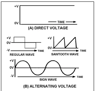
VOLTAGE WAVEFORMS
[image:15.612.149.462.382.681.2]<RXQRZNQRZWKDWWKHUHDUHWZRW\SHVRIFXUUHQWDQGYROWDJHWKDWLVGLUHFWFXUUHQWDQGYROWDJHDQG DOWHUQDWLQJFXUUHQWDQGYROWDJH,IDJUDSKLVFRQVWUXFWHGVKRZLQJWKHDPSOLWXGHRIDGFYROWDJHDFURVVWKH WHUPLQDOVRIDEDWWHU\ZLWKUHVSHFWWRWLPHLWZLOODSSHDULQILJXUHYLHZ$7KHGFYROWDJHLVVKRZQWR KDYHDFRQVWDQWDPSOLWXGH6RPHYROWDJHVJRWKURXJKSHULRGLFFKDQJHVLQDPSOLWXGHOLNHWKRVHVKRZQLQ ILJXUHYLHZ%7KHSDWWHUQZKLFKUHVXOWVZKHQWKHVHFKDQJHVLQDPSOLWXGHZLWKUHVSHFWWRWLPHDUH SORWWHGRQJUDSKSDSHULVNQRZQDVD:$9()250)LJXUHYLHZ%VKRZVVRPHRIWKHFRPPRQ HOHFWULFDOZDYHIRUPV2IWKRVHLOOXVWUDWHGWKHVLQHZDYHZLOOEHGHDOWZLWKPRVWRIWHQ
ELECTROMAGNETISM 7KHVLQHZDYHLOOXVWUDWHGLQILJXUHYLHZ%LVDSORWRIDFXUUHQWZKLFKFKDQJHVDPSOLWXGHDQG GLUHFWLRQ$OWKRXJKWKHUHDUHVHYHUDOZD\VRISURGXFLQJWKLVFXUUHQWWKHPHWKRGEDVHGRQWKHSULQFLSOHV RIHOHFWURPDJQHWLFLQGXFWLRQLVE\IDUWKHHDVLHVWDQGPRVWFRPPRQPHWKRGLQXVH 7KHIXQGDPHQWDOWKHRULHVFRQFHUQLQJVLPSOHPDJQHWVDQGPDJQHWLVPZHUHGLVFXVVHGLQ0RGXOH EXWKRZPDJQHWLVPFDQEHXVHGWRSURGXFHHOHFWULFLW\ZDVRQO\EULHIO\PHQWLRQHG7KLVPRGXOHZLOOJLYH \RXDPRUHLQGHSWKVWXG\RIPDJQHWLVP7KHPDLQSRLQWVWKDWZLOOEHH[SODLQHGDUHKRZPDJQHWLVPLV DIIHFWHGE\DQHOHFWULFFXUUHQWDQGFRQYHUVHO\KRZHOHFWULFLW\LVDIIHFWHGE\PDJQHWLVP7KLVJHQHUDO VXEMHFWDUHDLVPRVWRIWHQUHIHUUHGWRDV(/(&7520$*1(7,607RSURSHUO\XQGHUVWDQGHOHFWULFLW\\RX PXVWILUVWEHFRPHIDPLOLDUZLWKWKHUHODWLRQVKLSVEHWZHHQPDJQHWLVPDQGHOHFWULFLW\)RUH[DPSOH\RX PXVWNQRZWKDW
• $QHOHFWULFFXUUHQWDOZD\VSURGXFHVVRPHIRUPRIPDJQHWLVP
• 7KHPRVWFRPPRQO\XVHGPHDQVIRUSURGXFLQJRUXVLQJHOHFWULFLW\LQYROYHVPDJQHWLVP • 7KHSHFXOLDUEHKDYLRURIHOHFWULFLW\XQGHUFHUWDLQFRQGLWLRQVLVFDXVHGE\PDJQHWLFLQIOXHQFHV
MAGNETIC FIELDS
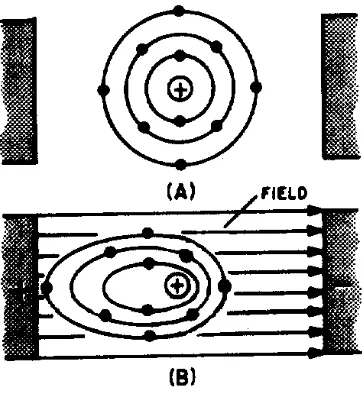
,Q+DQV&KULVWLDQ2HUVWHGD'DQLVKSK\VLFLVWIRXQGWKDWDGHILQLWHUHODWLRQVKLSH[LVWVEHWZHHQ PDJQHWLVPDQGHOHFWULFLW\+HGLVFRYHUHGWKDWDQHOHFWULFFXUUHQWLVDOZD\VDFFRPSDQLHGE\FHUWDLQ PDJQHWLFHIIHFWVDQGWKDWWKHVHHIIHFWVREH\GHILQLWHODZV
MAGNETIC FIELD AROUND A CURRENT-CARRYING CONDUCTOR
,QILJXUH$WKHQHHGOHGHIOHFWLRQVVKRZWKDWDPDJQHWLFILHOGH[LVWVLQFLUFXODUIRUPDURXQGWKH
FRQGXFWRU:KHQWKHFXUUHQWIORZVXSZDUGVHHILJXUH$WKHGLUHFWLRQRIWKHILHOGLVFORFNZLVHDV YLHZHGIURPWKHWRS+RZHYHULI\RXUHYHUVHWKHSRODULW\RIWKHEDWWHU\VRWKDWWKHFXUUHQWIORZV GRZQZDUGVHHILJXUH%WKHGLUHFWLRQRIWKHILHOGLVFRXQWHUFORFNZLVH
7KHUHODWLRQEHWZHHQWKHGLUHFWLRQRIWKHPDJQHWLFOLQHVRIIRUFHDURXQGDFRQGXFWRUDQGWKH GLUHFWLRQRIHOHFWURQFXUUHQWIORZLQWKHFRQGXFWRUPD\EHGHWHUPLQHGE\PHDQVRIWKH/()7+$1' 58/()25$&21'8&725LI\RXJUDVSWKHFRQGXFWRULQ\RXUOHIWKDQGZLWKWKHWKXPEH[WHQGHGLQ WKHGLUHFWLRQRIWKHHOHFWURQIORZFXUUHQW−WR\RXUILQJHUVZLOOSRLQWLQWKHGLUHFWLRQRIWKHPDJQHWLF OLQHVRIIRUFH1RZDSSO\WKLVUXOHWRILJXUH1RWHWKDW\RXUILQJHUVSRLQWLQWKHGLUHFWLRQWKDWWKHQRUWK SROHRIWKHFRPSDVVSRLQWVZKHQLWLVSODFHGLQWKHPDJQHWLFILHOGVXUURXQGLQJWKHZLUH
Figure 1-3.—Magnetic field around a current-carrying conductor, detailed view.
Figure 1-4.—Magnetic field around two parallel conductors.
Q6. When placed in the vicinity of a current-carrying conductor, the needle of a compass becomes aligned at what angle to the conductor?
Q7. What is the direction of the magnetic field around a vertical conductor when (a) the current flows upward and (b) the current flows downward.
Q8. The "left-hand rule" for a conductor is used for what purpose
Q9. In what direction will the compass needle point when the compass is placed in the magnetic field surrounding a wire?
Q10. When two adjacent parallel wires carry current in the same direction, the magnetic field about one wire has what effect on the magnetic field about the other conductor?
Q11.When two adjacent parallel conductors carry current in opposite directions, the magnetic field about one conductor has what effect on the magnetic field about the other conductor?
MAGNETIC FIELD OF A COIL
Figure 1-5.—Magnetic field produced by a current-carrying coil.
:KHQFXUUHQWLVSDVVHGWKURXJKWKHFRLOWKHPDJQHWLFILHOGDERXWHDFKWXUQRIZLUHOLQNVZLWKWKH ILHOGVRIWKHDGMDFHQWWXUQV6HHILJXUH$7KHFRPELQHGLQIOXHQFHRIDOOWKHWXUQVSURGXFHVDWZR SROHILHOGVLPLODUWRWKDWRIDVLPSOHEDUPDJQHW2QHHQGRIWKHFRLOLVDQRUWKSROHDQGWKHRWKHUHQGLVD VRXWKSROH
Polarity of an Electromagnetic Coil
)LJXUHVKRZVWKDWWKHGLUHFWLRQRIWKHPDJQHWLFILHOGDURXQGDVWUDLJKWZLUHGHSHQGVRQWKH
GLUHFWLRQRIFXUUHQWLQWKDWZLUH7KXVDUHYHUVDORIFXUUHQWLQDZLUHFDXVHVDUHYHUVDOLQWKHGLUHFWLRQRI WKHPDJQHWLFILHOGWKDWLVSURGXFHG,WIROORZVWKDWDUHYHUVDORIWKHFXUUHQWLQDFRLODOVRFDXVHVDUHYHUVDO RIWKHWZRSROHPDJQHWLFILHOGDERXWWKHFRLO
Strength of an Electromagnetic Field
7KHVWUHQJWKRULQWHQVLW\RIDFRLOVPDJQHWLFILHOGGHSHQGVRQDQXPEHURIIDFWRUV7KHPDLQRQHV
DUHOLVWHGEHORZDQGZLOOEHGLVFXVVHGDJDLQODWHU
• 7KHQXPEHURIWXUQVRIZLUHLQWKHFRLO
• 7KHDPRXQWRIFXUUHQWIORZLQJLQWKHFRLO • 7KHUDWLRRIWKHFRLOOHQJWKWRWKHFRLOZLGWK • 7KHW\SHRIPDWHULDOLQWKHFRUH
Losses in an Electromagnetic Field
:KHQFXUUHQWIORZVLQDFRQGXFWRUWKHDWRPVLQWKHFRQGXFWRUDOOOLQHXSLQDGHILQLWHGLUHFWLRQ SURGXFLQJDPDJQHWLFILHOG:KHQWKHGLUHFWLRQRIWKHFXUUHQWFKDQJHVWKHGLUHFWLRQRIWKHDWRPV DOLJQPHQWDOVRFKDQJHVFDXVLQJWKHPDJQHWLFILHOGWRFKDQJHGLUHFWLRQ7RUHYHUVHDOOWKHDWRPVUHTXLUHV WKDWSRZHUEHH[SHQGHGDQGWKLVSRZHULVORVW7KLVORVVRISRZHULQWKHIRUPRIKHDWLVFDOOHG +<67(5(6,6/266+\VWHUHVLVORVVLVFRPPRQWRDOODFHTXLSPHQWKRZHYHULWFDXVHVIHZSUREOHPV H[FHSWLQPRWRUVJHQHUDWRUVDQGWUDQVIRUPHUV:KHQWKHVHGHYLFHVDUHGLVFXVVHGODWHULQWKLVPRGXOH K\VWHUHVLVORVVZLOOEHFRYHUHGLQPRUHGHWDLO
Q12. What is the shape of the magnetic field that exists around (a) a straight conductor and (b) a coil?
Q13. What happens to the two-pole field of a coil when the current through the coil is reversed?
Q14. What rule is used to determine the polarity of a coil when the direction of the electron current flow in the coil is known?
Q15. State the rule whose purpose is described in Q14.
BASIC AC GENERATION
LQGXFHGLQWKHFRQGXFWRULVPD[LPXP:KHQWKHYDOXHRILQGXFHGYROWDJHDWYDULRXVSRLQWVGXULQJWKH URWDWLRQIURP$WR%LVSORWWHGRQDJUDSKDQGWKHSRLQWVFRQQHFWHGDFXUYHDSSHDUVDVVKRZQEHORZ
Figure 1-7.—Simple alternating-current generator.
$VWKHORRSFRQWLQXHVWREHURWDWHGWRZDUGWKHSRVLWLRQVKRZQEHORZLQ&LWFXWVIHZHUDQGIHZHU OLQHVRIIRUFH7KHLQGXFHGYROWDJHGHFUHDVHVIURPLWVSHDNYDOXH(YHQWXDOO\WKHORRSLVRQFHDJDLQ PRYLQJLQDSODQHSDUDOOHOWRWKHPDJQHWLFILHOGDQGQRHPILVLQGXFHGLQWKHFRQGXFWRU
7KHORRSKDVQRZEHHQURWDWHGWKURXJKKDOIDFLUFOHRQHDOWHUQDWLRQRU,IWKHSUHFHGLQJ
TXDUWHUF\FOHLVSORWWHGLWDSSHDUVDVVKRZQEHORZ
:KHQWKHVDPHSURFHGXUHLVDSSOLHGWRWKHVHFRQGKDOIRIURWDWLRQWKURXJKWKHFXUYH
DSSHDUVDVVKRZQEHORZ1RWLFHWKHRQO\GLIIHUHQFHLVLQWKHSRODULW\RIWKHLQGXFHGYROWDJH:KHUH SUHYLRXVO\WKHSRODULW\ZDVSRVLWLYHLWLVQRZQHJDWLYH
7KHVLQHFXUYHVKRZVWKHYDOXHRILQGXFHGYROWDJHDWHDFKLQVWDQWRIWLPHGXULQJURWDWLRQRIWKHORRS 1RWLFHWKDWWKLVFXUYHFRQWDLQVRUWZRDOWHUQDWLRQV7:2$/7(51$7,216UHSUHVHQW21(
$VVXPLQJDFORVHGSDWKLVSURYLGHGDFURVVWKHHQGVRIWKHFRQGXFWRUORRS\RXFDQGHWHUPLQHWKH GLUHFWLRQRIFXUUHQWLQWKHORRSE\XVLQJWKH/()7+$1'58/()25*(1(5$72565HIHUWRILJXUH 7KHOHIWKDQGUXOHLVDSSOLHGDVIROORZV)LUVWSODFH\RXUOHIWKDQGRQWKHLOOXVWUDWLRQZLWKWKHILQJHUV DVVKRZQ<RXU7+80%ZLOOQRZSRLQWLQWKHGLUHFWLRQRIURWDWLRQUHODWLYHPRYHPHQWRIWKHZLUHWRWKH PDJQHWLFILHOG\RXU)25(),1*(5ZLOOSRLQWLQWKHGLUHFWLRQRIPDJQHWLFIOX[QRUWKWRVRXWKDQG \RXU0,''/(),1*(5SRLQWLQJRXWRIWKHSDSHUZLOOSRLQWLQWKHGLUHFWLRQRIHOHFWURQFXUUHQWIORZ
Figure 1-9.—Left-hand rule for generators.
$VPHQWLRQHGSUHYLRXVO\WKHF\FOHFRQVLVWVRIWZRFRPSOHWHDOWHUQDWLRQVLQDSHULRGRIWLPH 5HFHQWO\WKH+(57=+]KDVEHHQGHVLJQDWHGWRLQGLFDWHRQHF\FOHSHUVHFRQG,I21(&<&/(3(5 6(&21'LV21(+(57=WKHQF\FOHVSHUVHFRQGDUHHTXDOWRKHUW]DQGVRRQ7KURXJKRXWWKH 1((76WKHWHUPF\FOHLVXVHGZKHQQRVSHFLILFWLPHHOHPHQWLVLQYROYHGDQGWKHWHUPKHUW]+]LVXVHG ZKHQWKHWLPHHOHPHQWLVPHDVXUHGLQVHFRQGV
Q16. When a conductor is rotated in a magnetic field, at what points in the cycle is emf (a) at maximum amplitude and (b) at minimum amplitude?
Q17. One cycle is equal to how many degrees of rotation of a conductor in a magnetic field?
Q18. State the left-hand rule used to determine the direction of current in a generator.
Q19. How is an ac voltage produced by an ac generator?
FREQUENCY ,IWKHORRSLQWKHILJXUH$PDNHVRQHFRPSOHWHUHYROXWLRQHDFKVHFRQGWKHJHQHUDWRUSURGXFHV RQHFRPSOHWHF\FOHRIDFGXULQJHDFKVHFRQG+],QFUHDVLQJWKHQXPEHURIUHYROXWLRQVWRWZRSHU VHFRQGZLOOSURGXFHWZRFRPSOHWHF\FOHVRIDFSHUVHFRQG+]7KHQXPEHURIFRPSOHWHF\FOHVRI DOWHUQDWLQJFXUUHQWRUYROWDJHFRPSOHWHGHDFKVHFRQGLVUHIHUUHGWRDVWKH)5(48(1&<)UHTXHQF\LV DOZD\VPHDVXUHGDQGH[SUHVVHGLQKHUW] $OWHUQDWLQJFXUUHQWIUHTXHQF\LVDQLPSRUWDQWWHUPWRXQGHUVWDQGVLQFHPRVWDFHOHFWULFDOHTXLSPHQWV UHTXLUHDVSHFLILFIUHTXHQF\IRUSURSHURSHUDWLRQ
Q20. Define Frequency.
Figure 1-10.—Period of a sine wave.
(DFKF\FOHRIWKHVLQHZDYHVKRZQLQILJXUHFRQVLVWVRIWZRLGHQWLFDOO\VKDSHGYDULDWLRQVLQ
YROWDJH7KHYDULDWLRQZKLFKRFFXUVGXULQJWKHWLPHWKHYROWDJHLVSRVLWLYHLVFDOOHGWKH326,7,9( $/7(51$7,217KHYDULDWLRQZKLFKRFFXUVGXULQJWKHWLPHWKHYROWDJHLVQHJDWLYHLVFDOOHGWKH 1(*$7,9($/7(51$7,21,QDVLQHZDYHWKHVHWZRDOWHUQDWLRQVDUHLGHQWLFDOLQVL]HDQGVKDSHEXW RSSRVLWHLQSRODULW\
7KHGLVWDQFHIURP]HURWRWKHPD[LPXPYDOXHRIHDFKDOWHUQDWLRQLVFDOOHGWKH$03/,78'(7KH
DPSOLWXGHRIWKHSRVLWLYHDOWHUQDWLRQDQGWKHDPSOLWXGHRIWKHQHJDWLYHDOWHUQDWLRQDUHWKHVDPH
WAVELENGTH
7KHWLPHLWWDNHVIRUDVLQHZDYHWRFRPSOHWHRQHF\FOHLVGHILQHGDVWKHSHULRGRIWKHZDYHIRUP7KH
GLVWDQFHWUDYHOHGE\WKHVLQHZDYHGXULQJWKLVSHULRGLVUHIHUUHGWRDV:$9(/(1*7+:DYHOHQJWK LQGLFDWHGE\WKHV\PEROȜ*UHHNODPEGDLVWKHGLVWDQFHDORQJWKHZDYHIRUPIURPRQHSRLQWWRWKHVDPH SRLQWRQWKHQH[WF\FOH<RXFDQREVHUYHWKLVUHODWLRQVKLSE\H[DPLQLQJILJXUH7KHSRLQWRQWKH ZDYHIRUPWKDWPHDVXUHPHQWRIZDYHOHQJWKEHJLQVLVQRWLPSRUWDQWDVORQJDVWKHGLVWDQFHLVPHDVXUHGWR WKHVDPHSRLQWRQWKHQH[WF\FOHVHHILJXUH
Figure 1-12.—Wavelength measurement.
Q21. What term is used to indicate the time of one complete cycle of a waveform?
Q22. What is a positive alternation?
Q23. :KDWGRWKHSHULRGDQGWKHZDYHOHQJWKRIDVLQHZDYHPHDVXUHUHVSHFWLYHO\"
ALTERNATING CURRENT VALUES
,QGLVFXVVLQJDOWHUQDWLQJFXUUHQWDQGYROWDJH\RXZLOORIWHQILQGLWQHFHVVDU\WRH[SUHVVWKHFXUUHQW DQGYROWDJHLQWHUPVRI0$;,080RU3($.YDOXHV3($.WR3($.YDOXHV())(&7,9(YDOXHV $9(5$*(YDOXHVRU,167$17$1(286YDOXHV(DFKRIWKHVHYDOXHVKDVDGLIIHUHQWPHDQLQJDQGLV XVHGWRGHVFULEHDGLIIHUHQWDPRXQWRIFXUUHQWRUYROWDJH
PEAK AND PEAK-TO-PEAK VALUES
5HIHUWRILJXUH1RWLFHLWVKRZVWKHSRVLWLYHDOWHUQDWLRQRIDVLQHZDYHDKDOIF\FOHRIDFDQGD
[image:26.612.224.391.80.231.2]'XULQJHDFKFRPSOHWHF\FOHRIDFWKHUHDUHDOZD\VWZRPD[LPXPRUSHDNYDOXHVRQHIRUWKHSRVLWLYH KDOIF\FOHDQGWKHRWKHUIRUWKHQHJDWLYHKDOIF\FOH7KHGLIIHUHQFHEHWZHHQWKHSHDNSRVLWLYHYDOXHDQG WKHSHDNQHJDWLYHYDOXHLVFDOOHGWKHSHDNWRSHDNYDOXHRIWKHVLQHZDYH7KLVYDOXHLVWZLFHWKH PD[LPXPRUSHDNYDOXHRIWKHVLQHZDYHDQGLVVRPHWLPHVXVHGIRUPHDVXUHPHQWRIDFYROWDJHV1RWHWKH GLIIHUHQFHEHWZHHQSHDNDQGSHDNWRSHDNYDOXHVLQILJXUH8VXDOO\DOWHUQDWLQJYROWDJHDQGFXUUHQW DUHH[SUHVVHGLQ())(&7,9(9$/8(6DWHUP\RXZLOOVWXG\ODWHUUDWKHUWKDQLQSHDNWRSHDNYDOXHV
Figure 1-14.—Peak and peak-to-peak values.
Q24. What is meant by peak and peak-to-peak values of ac?
Q25. How many times is the maximum or peak value of emf or current reached during one cycle of ac?
INSTANTANEOUS VALUE 7KH,167$17$1(286YDOXHRIDQDOWHUQDWLQJYROWDJHRUFXUUHQWLVWKHYDOXHRIYROWDJHRUFXUUHQW DWRQHSDUWLFXODULQVWDQW7KHYDOXHPD\EH]HURLIWKHSDUWLFXODULQVWDQWLVWKHWLPHLQWKHF\FOHDWZKLFK WKHSRODULW\RIWKHYROWDJHLVFKDQJLQJ,WPD\DOVREHWKHVDPHDVWKHSHDNYDOXHLIWKHVHOHFWHGLQVWDQWLV WKHWLPHLQWKHF\FOHDWZKLFKWKHYROWDJHRUFXUUHQWVWRSVLQFUHDVLQJDQGVWDUWVGHFUHDVLQJ7KHUHDUH DFWXDOO\DQLQILQLWHQXPEHURILQVWDQWDQHRXVYDOXHVEHWZHHQ]HURDQGWKHSHDNYDOXH AVERAGE VALUE 7KH$9(5$*(YDOXHRIDQDOWHUQDWLQJFXUUHQWRUYROWDJHLVWKHDYHUDJHRI$//WKH ,167$17$1(286YDOXHVGXULQJ21(DOWHUQDWLRQ6LQFHWKHYROWDJHLQFUHDVHVIURP]HURWRSHDNYDOXH DQGGHFUHDVHVEDFNWR]HURGXULQJRQHDOWHUQDWLRQWKHDYHUDJHYDOXHPXVWEHVRPHYDOXHEHWZHHQWKRVH WZROLPLWV<RXFRXOGGHWHUPLQHWKHDYHUDJHYDOXHE\DGGLQJWRJHWKHUDVHULHVRILQVWDQWDQHRXVYDOXHVRI
WKHDOWHUQDWLRQEHWZHHQDQGDQGWKHQGLYLGLQJWKHVXPE\WKHQXPEHURILQVWDQWDQHRXVYDOXHV
XVHG7KHFRPSXWDWLRQZRXOGVKRZWKDWRQHDOWHUQDWLRQRIDVLQHZDYHKDVDQDYHUDJHYDOXHHTXDOWR WLPHVWKHSHDNYDOXH7KHIRUPXODIRUDYHUDJHYROWDJHLV
Eavg = 0.636 × Emax
Iavg = 0.636 × Imax
ZKHUH,DYJLVWKHDYHUDJHFXUUHQWLQRQHDOWHUQDWLRQDQG,PD[LVWKHPD[LPXPRUSHDNFXUUHQW
'RQRWFRQIXVHWKHDERYHGHILQLWLRQRIDQDYHUDJHYDOXHZLWKWKDWRIWKHDYHUDJHYDOXHRIDFRPSOHWH F\FOH%HFDXVHWKHYROWDJHLVSRVLWLYHGXULQJRQHDOWHUQDWLRQDQGQHJDWLYHGXULQJWKHRWKHUDOWHUQDWLRQWKH DYHUDJHYDOXHRIWKHYROWDJHYDOXHVRFFXUULQJGXULQJWKHFRPSOHWHF\FOHLV]HUR
Q26. If any point on a sine wave is selected at random and the value of the current or voltage is measured at that one particular moment, what value is being measured?
Q27. What value of current or voltage is computed by averaging all of the instantaneous values during the negative alternation of a sine wave?
Q28. What is the average value of all of the instantaneous currents or voltages occurring during one complete cycle of a sine wave?
Q29. What mathematical formulas are used to find the average value of current and average value of voltage of a sine wave?
Q30. If Emax is 115 volts, what is Eavg?
Q31. If Iavg is 1.272 ampere, what is Imax?
EFFECTIVE VALUE OF A SINE WAVE
(PD[(DYJ,PD[DQG,DYJDUHYDOXHVXVHGLQDFPHDVXUHPHQWV$QRWKHUYDOXHXVHGLVWKH())(&7,9( YDOXHRIDF7KLVLVWKHYDOXHRIDOWHUQDWLQJYROWDJHRUFXUUHQWWKDWZLOOKDYHWKHVDPHHIIHFWRQDUHVLVWDQFH DVDFRPSDUDEOHYDOXHRIGLUHFWYROWDJHRUFXUUHQWZLOOKDYHRQWKHVDPHUHVLVWDQFH
,QDQHDUOLHUGLVFXVVLRQ\RXZHUHWROGWKDWZKHQFXUUHQWIORZVLQDUHVLVWDQFHKHDWLVSURGXFHG:KHQ GLUHFWFXUUHQWIORZVLQDUHVLVWDQFHWKHDPRXQWRIHOHFWULFDOSRZHUFRQYHUWHGLQWRKHDWHTXDOV,5ZDWWV +RZHYHUVLQFHDQDOWHUQDWLQJFXUUHQWKDYLQJDPD[LPXPYDOXHRIDPSHUHGRHVQRWPDLQWDLQDFRQVWDQW YDOXHWKHDOWHUQDWLQJFXUUHQWZLOOQRWSURGXFHDVPXFKKHDWLQWKHUHVLVWDQFHDVZLOODGLUHFWFXUUHQWRI DPSHUH
([DPLQHYLHZV$DQG%RIILJXUHDQGQRWLFHWKDWWKHKHDW&SURGXFHGE\DPSHUHRI
DOWHUQDWLQJFXUUHQWWKDWLVDQDFZLWKDPD[LPXPYDOXHRIDPSHUHLVRQO\SHUFHQWRIWKHKHDW &SURGXFHGE\DPSHUHRIGLUHFWFXUUHQW0DWKHPDWLFDOO\
7KHUHIRUHIRUHIIHFWLYHYDOXHRIDF,HII ×,PD[
7KHUDWHDWZKLFKKHDWLVSURGXFHGLQDUHVLVWDQFHIRUPVDFRQYHQLHQWEDVLVIRUHVWDEOLVKLQJDQ HIIHFWLYHYDOXHRIDOWHUQDWLQJFXUUHQWDQGLVNQRZQDVWKHKHDWLQJHIIHFWPHWKRG$QDOWHUQDWLQJFXUUHQW LVVDLGWRKDYHDQHIIHFWLYHYDOXHRIRQHDPSHUHZKHQLWSURGXFHVKHDWLQDJLYHQUHVLVWDQFHDWWKHVDPH UDWHDVGRHVRQHDPSHUHRIGLUHFWFXUUHQW <RXFDQFRPSXWHWKHHIIHFWLYHYDOXHRIDVLQHZDYHRIFXUUHQWWRDIDLUGHJUHHRIDFFXUDF\E\WDNLQJ HTXDOO\VSDFHGLQVWDQWDQHRXVYDOXHVRIFXUUHQWDORQJWKHFXUYHDQGH[WUDFWLQJWKHVTXDUHURRWRIWKH DYHUDJHRIWKHVXPRIWKHVTXDUHGYDOXHV )RUWKLVUHDVRQWKHHIIHFWLYHYDOXHLVRIWHQFDOOHGWKHURRWPHDQVTXDUHUPVYDOXH7KXV
6WDWHGDQRWKHUZD\WKHHIIHFWLYHRUUPVYDOXH,HIIRIDVLQHZDYHRIFXUUHQWLVWLPHVWKH
PD[LPXPYDOXHRIFXUUHQW,PD[7KXV,HII ×,PD[:KHQ,HIILVNQRZQ\RXFDQILQG,PD[E\XVLQJ
WKHIRUPXOD,PD[ ×,HII<RXPLJKWZRQGHUZKHUHWKHFRQVWDQWFRPHVIURP7RILQGRXW
H[DPLQHILJXUHDJDLQDQGUHDGWKHIROORZLQJH[SODQDWLRQ$VVXPHWKDWWKHGFLQILJXUH$LV PDLQWDLQHGDWDPSHUHDQGWKHUHVLVWRUWHPSHUDWXUHDW&$OVRDVVXPHWKDWWKHDFLQILJXUH% LVLQFUHDVHGXQWLOWKHWHPSHUDWXUHRIWKHUHVLVWRULV&$WWKLVSRLQWLWLVIRXQGWKDWDPD[LPXPDF YDOXHRIDPSHUHVLVUHTXLUHGLQRUGHUWRKDYHWKHVDPHKHDWLQJHIIHFWDVGLUHFWFXUUHQW7KHUHIRUHLQ WKHDFFLUFXLWWKHPD[LPXPFXUUHQWUHTXLUHGLVWLPHVWKHHIIHFWLYHFXUUHQW,WLVLPSRUWDQWIRU\RXWR UHPHPEHUWKHDERYHUHODWLRQVKLSDQGWKDWWKHHIIHFWLYHYDOXH,HIIRIDQ\VLQHZDYHRIFXUUHQWLVDOZD\V
WLPHVWKHPD[LPXPYDOXH,PD[
6LQFHDOWHUQDWLQJFXUUHQWLVFDXVHGE\DQDOWHUQDWLQJYROWDJHWKHUDWLRRIWKHHIIHFWLYHYDOXHRI YROWDJHWRWKHPD[LPXPYDOXHRIYROWDJHLVWKHVDPHDVWKHUDWLRRIWKHHIIHFWLYHYDOXHRIFXUUHQWWRWKH PD[LPXPYDOXHRIFXUUHQW6WDWHGDQRWKHUZD\WKHHIIHFWLYHRUUPVYDOXH(HIIRIDVLQHZDYHRIYROWDJH
:KHQDQDOWHUQDWLQJFXUUHQWRUYROWDJHYDOXHLVVSHFLILHGLQDERRNRURQDGLDJUDPWKHYDOXHLVDQ
HIIHFWLYHYDOXHXQOHVVWKHUHLVDGHILQLWHVWDWHPHQWWRWKHFRQWUDU\5HPHPEHUWKDWDOOPHWHUVXQOHVV PDUNHGWRWKHFRQWUDU\DUHFDOLEUDWHGWRLQGLFDWHHIIHFWLYHYDOXHVRIFXUUHQWDQGYROWDJH
3UREOHP$FLUFXLWLVNQRZQWRKDYHDQDOWHUQDWLQJYROWDJHRIYROWVDQGDSHDNRUPD[LPXP
FXUUHQWRIDPSHUHV:KDWDUHWKHSHDNYROWDJHDQGHIIHFWLYHFXUUHQWYDOXHV"
)LJXUHVKRZVWKHUHODWLRQVKLSEHWZHHQWKHYDULRXVYDOXHVXVHGWRLQGLFDWHVLQHZDYHDPSOLWXGH
Figure 1-16.—Various values used to indicate sine-wave amplitude.
Q32. What is the most convenient basis for comparing alternating and direct voltages and currents?
Q33. What value of ac is used as a comparison to dc?
Q34. What is the formula for finding the effective value of an alternating current?
Q35. If the peak value of a sine wave is 1,000 volts, what is the effective (Eeff) value?
Q36. If Ieff = 4.25 ampere, what is Imax?
SINE WAVES IN PHASE
:KHQDVLQHZDYHRIYROWDJHLVDSSOLHGWRDUHVLVWDQFHWKHUHVXOWLQJFXUUHQWLVDOVRDVLQHZDYH7KLV IROORZV2KPVODZZKLFKVWDWHVWKDWFXUUHQWLVGLUHFWO\SURSRUWLRQDOWRWKHDSSOLHGYROWDJH1RZH[DPLQH ILJXUH1RWLFHWKDWWKHVLQHZDYHRIYROWDJHDQGWKHUHVXOWLQJVLQHZDYHRIFXUUHQWDUHVXSHULPSRVHG RQWKHVDPHWLPHD[LV1RWLFHDOVRWKDWDVWKHYROWDJHLQFUHDVHVLQDSRVLWLYHGLUHFWLRQWKHFXUUHQW
Figure 1-17.—Voltage and current waves in phase.
,QVRPHFLUFXLWVVHYHUDOVLQHZDYHVFDQEHLQSKDVHZLWKHDFKRWKHU7KXVLWLVSRVVLEOHWRKDYHWZR
RUPRUHYROWDJHGURSVLQSKDVHZLWKHDFKRWKHUDQGDOVREHLQSKDVHZLWKWKHFLUFXLWFXUUHQW
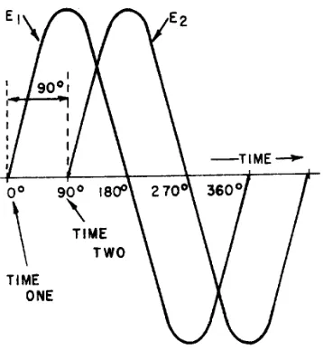
SINE WAVES OUT OF PHASE
)LJXUHVKRZVYROWDJHZDYH(ZKLFKLVFRQVLGHUHGWRVWDUWDWWLPHRQH$VYROWDJHZDYH(
UHDFKHVLWVSRVLWLYHSHDNYROWDJHZDYH(VWDUWVLWVULVHWLPHWZR6LQFHWKHVHYROWDJHZDYHVGRQRWJR WKURXJKWKHLUPD[LPXPDQGPLQLPXPSRLQWVDWWKHVDPHLQVWDQWRIWLPHD3+$6(',))(5(1&(H[LVWV EHWZHHQWKHWZRZDYHV7KHWZRZDYHVDUHVDLGWREH2872)3+$6()RUWKHWZRZDYHVLQILJXUH
WKHSKDVHGLIIHUHQFHLV
[image:32.612.218.397.468.667.2]
7RIXUWKHUGHVFULEHWKHSKDVHUHODWLRQVKLSEHWZHHQWZRVLQHZDYHVWKHWHUPV/($'DQG/$*DUH
XVHG7KHDPRXQWE\ZKLFKRQHVLQHZDYHOHDGVRUODJVDQRWKHUVLQHZDYHLVPHDVXUHGLQGHJUHHV5HIHU DJDLQWRILJXUH2EVHUYHWKDWZDYH(VWDUWVODWHULQWLPHWKDQGRHVZDYH(<RXFDQDOVR GHVFULEHWKLVUHODWLRQVKLSE\VD\LQJWKDWZDYH(OHDGVZDYH(E\RUWKDWZDYH(ODJVZDYH(E\ (LWKHUVWDWHPHQWLVFRUUHFWLWLVWKHSKDVHUHODWLRQVKLSEHWZHHQWKHWZRVLQHZDYHVWKDWLV LPSRUWDQW ,WLVSRVVLEOHIRURQHVLQHZDYHWROHDGRUODJDQRWKHUVLQHZDYHE\DQ\QXPEHURIGHJUHHVH[FHSW RU:KHQWKHODWWHUFRQGLWLRQH[LVWVWKHWZRZDYHVDUHVDLGWREHLQSKDVH7KXVWZRVLQHZDYHV WKDWGLIIHULQSKDVHE\DUHDFWXDOO\RXWRISKDVHZLWKHDFKRWKHUZKHUHDVWZRVLQHZDYHVWKDWGLIIHULQ SKDVHE\DUHFRQVLGHUHGWREHLQSKDVHZLWKHDFKRWKHU $SKDVHUHODWLRQVKLSWKDWLVTXLWHFRPPRQLVVKRZQLQILJXUH1RWLFHWKDWWKHWZRZDYHV LOOXVWUDWHGGLIIHULQSKDVHE\1RWLFHDOVRWKDWDOWKRXJKWKHZDYHVSDVVWKURXJKWKHLUPD[LPXPDQG PLQLPXPYDOXHVDWWKHVDPHWLPHWKHLULQVWDQWDQHRXVYROWDJHVDUHDOZD\VRIRSSRVLWHSRODULW\,IWZR VXFKZDYHVH[LVWDFURVVWKHVDPHFRPSRQHQWDQGWKHZDYHVDUHRIHTXDODPSOLWXGHWKH\FDQFHOHDFK RWKHU:KHQWKH\KDYHGLIIHUHQWDPSOLWXGHVWKHUHVXOWDQWZDYHKDVWKHVDPHSRODULW\DVWKHODUJHUZDYH DQGKDVDQDPSOLWXGHHTXDOWRWKHGLIIHUHQFHEHWZHHQWKHDPSOLWXGHVRIWKHWZRZDYHV
Figure 1-19.—Voltage waves 180º out of phase.
7RGHWHUPLQHWKHSKDVHGLIIHUHQFHEHWZHHQWZRVLQHZDYHVORFDWHWKHSRLQWVRQWKHWLPHD[LVZKHUH
WKHWZRZDYHVFURVVWKHWLPHD[LVWUDYHOLQJLQWKHVDPHGLUHFWLRQ7KHQXPEHURIGHJUHHVEHWZHHQWKH FURVVLQJSRLQWVLVWKHSKDVHGLIIHUHQFH7KHZDYHWKDWFURVVHVWKHD[LVDWWKHODWHUWLPHWRWKHULJKWRQWKH WLPHD[LVLVVDLGWRODJWKHRWKHUZDYH
Q37. When are the voltage wave and the current wave in a circuit considered to be in phase?
Q38. When are two voltage waves considered to be out of phase?
Q39. What is the phase relationship between two voltage waves that differ in phase by 360° ?
OHM'S LAW IN AC CIRCUITS
0DQ\DFFLUFXLWVFRQWDLQUHVLVWDQFHRQO\7KHUXOHVIRUWKHVHFLUFXLWVDUHWKHVDPHUXOHVWKDWDSSO\WR GFFLUFXLWV5HVLVWRUVODPSVDQGKHDWLQJHOHPHQWVDUHH[DPSOHVRIUHVLVWLYHHOHPHQWV:KHQDQDFFLUFXLW FRQWDLQVRQO\UHVLVWDQFH2KPV/DZ.LUFKKRIIV/DZDQGWKHYDULRXVUXOHVWKDWDSSO\WRYROWDJHFXUUHQW DQGSRZHULQDGFFLUFXLWDOVRDSSO\WRWKHDFFLUFXLW7KH2KPV/DZIRUPXODIRUDQDFFLUFXLWFDQEH VWDWHGDV
5HPHPEHUXQOHVVRWKHUZLVHVWDWHGDOODFYROWDJHDQGFXUUHQWYDOXHVDUHJLYHQDVHIIHFWLYHYDOXHV 7KHIRUPXODIRU2KPV/DZFDQDOVREHVWDWHGDV
7KHLPSRUWDQWWKLQJWRNHHSLQPLQGLV'R1RWPL[DFYDOXHV:KHQ\RXVROYHIRUHIIHFWLYHYDOXHV
7KHSUREOHPKRZHYHUDVNHGIRUWKHDYHUDJHYDOXHRIFXUUHQW,DYJ7RFRQYHUWWKHHIIHFWLYHYDOXH RIFXUUHQWWRWKHDYHUDJHYDOXHRIFXUUHQW\RXPXVWILUVWGHWHUPLQHWKHSHDNRUPD[LPXPYDOXHRIFXUUHQW ,PD[
<RXFDQQRZILQG,DYJ-XVWVXEVWLWXWHDPSHUHVLQWKH,DYJIRUPXODDQGVROYHIRU,DYJ
5HPHPEHU\RXFDQXVHWKH2KPV/DZIRUPXODVWRVROYHDQ\SXUHO\UHVLVWLYHDFFLUFXLWSUREOHP
8VHWKHIRUPXODVLQWKHVDPHPDQQHUDV\RXZRXOGWRVROYHDGFFLUFXLWSUREOHP
Q41. A series circuit consists of three resistors (R1 = 10Ω, R2 = 20Ω, R3 = 15Ω) and an alternating voltage source of 100 volts. What is the effective value of current in the circuit?
Q42. If the alternating source in Q41 is changed to 200 volts peak-to-peak, what is Iavg?
Q43. If Eeff is 130 volts and Ieff is 3 amperes, what is the total resistance (RT) in the circuit?
SUMMARY
%HIRUHJRLQJRQWRFKDSWHUUHDGWKHIROORZLQJVXPPDU\RIWKHPDWHULDOLQFKDSWHU7KLVVXPPDU\
ZLOOUHLQIRUFHZKDW\RXKDYHDOUHDG\OHDUQHG
DC AND AC²'LUHFWFXUUHQWIORZVLQRQHGLUHFWLRQRQO\ZKLOHDOWHUQDWLQJFXUUHQWLVFRQVWDQWO\
FKDQJLQJLQDPSOLWXGHDQGGLUHFWLRQ
ADVANTAGES AND DISADVANTAGES OF AC AND DC²'LUHFWFXUUHQWKDVVHYHUDO
VWHSSHGGRZQDWWKHFRQVXPHUHQGWKURXJKWKHXVHRIDWUDQVIRUPHUWRZKDWHYHUYROWDJHOHYHOLVUHTXLUHG E\WKHORDG6LQFHSRZHULQDGFV\VWHPPXVWEHWUDQVPLWWHGDWORZYROWDJHDQGKLJKFXUUHQWOHYHOVWKH ,5SRZHUORVVEHFRPHVDSUREOHPLQWKHGFV\VWHP6LQFHSRZHULQDQDFV\VWHPFDQEHWUDQVPLWWHGDWD KLJKYROWDJHOHYHODQGDORZFXUUHQWOHYHOWKH,5SRZHUORVVLQWKHDFV\VWHPLVPXFKOHVVWKDQWKDWLQWKH GFV\VWHP
VOLTAGE WAVEFORMS²7KHZDYHIRUPRIYROWDJHRUFXUUHQWLVDJUDSKLFDOSLFWXUHRIFKDQJHV
LQYROWDJHRUFXUUHQWYDOXHVRYHUDSHULRGRIWLPH
ELECTROMAGNETISM²:KHQDFRPSDVVLVSODFHGLQWKHYLFLQLW\RIDFXUUHQWFDUU\LQJ
FRQGXFWRUWKHQHHGOHDOLJQVLWVHOIDWULJKWDQJOHVWRWKHFRQGXFWRU7KHQRUWKSROHRIWKHFRPSDVV
$UURZVDUHJHQHUDOO\XVHGLQHOHFWULFDOGLDJUDPVWRLQGLFDWHWKHGLUHFWLRQRIFXUUHQWLQDZLUH$FURVV RQWKHHQGRIDFURVVVHFWLRQDOYLHZRIDZLUHLQGLFDWHVWKDWFXUUHQWLVIORZLQJDZD\IURP\RXZKLOHD GRWÂLQGLFDWHVWKDWFXUUHQWLVIORZLQJWRZDUG\RX
:KHQWZRDGMDFHQWSDUDOOHOFRQGXFWRUVFDUU\FXUUHQWLQWKHVDPHGLUHFWLRQWKHPDJQHWLFILHOGV DURXQGWKHFRQGXFWRUVDLGHDFKRWKHU:KHQWKHFXUUHQWVLQWKHWZRFRQGXFWRUVIORZLQRSSRVLWH GLUHFWLRQVWKHILHOGVDURXQGWKHFRQGXFWRUVRSSRVHHDFKRWKHU
MAGNETIC FIELD OF A COIL²:KHQZLUHLVZRXQGDURXQGDFRUHLWIRUPVD&2,/7KH
PDJQHWLFILHOGVSURGXFHGZKHQFXUUHQWIORZVLQWKHFRLOFRPELQH7KHFRPELQHGLQIOXHQFHRIDOORIWKH ILHOGVDURXQGWKHWXUQVSURGXFHDWZRSROHILHOGVLPLODUWRWKDWRIDVLPSOHEDUPDJQHW
:KHQWKHGLUHFWLRQRIFXUUHQWLQWKHFRLOLVUHYHUVHGWKHSRODULW\RIWKHWZRSROHILHOGRIWKHFRLOLV UHYHUVHG
7KHVWUHQJWKRIWKHPDJQHWLFILHOGRIWKHFRLOLVGHSHQGHQWXSRQ
• 7KHQXPEHURIWXUQVRIWKHZLUHLQWKHFRLO
• 7KHDPRXQWRIFXUUHQWLQWKHFRLO
• 7KHW\SHRIPDWHULDOLQWKHFRUH
BASIC AC GENERATION²:KHQDFRQGXFWRULVLQDPDJQHWLFILHOGDQGHLWKHUWKHILHOGRUWKH
FRQGXFWRUPRYHVDQHPIYROWDJHLVLQGXFHGLQWKHFRQGXFWRU7KLVHIIHFWLVFDOOHGHOHFWURPDJQHWLF LQGXFWLRQ
$ORRSRIZLUHURWDWLQJLQDPDJQHWLFILHOGSURGXFHVDYROWDJHZKLFKFRQVWDQWO\FKDQJHVLQDPSOLWXGH DQGGLUHFWLRQ7KHZDYHIRUPSURGXFHGLVFDOOHGDVLQHZDYHDQGLVDJUDSKLFDOSLFWXUHRIDOWHUQDWLQJ
FXUUHQWDF2QHFRPSOHWHUHYROXWLRQRIWKHFRQGXFWRUSURGXFHVRQHF\FOHRIDF7KHF\FOHLV
FRPSRVHGRIWZRDOWHUQDWLRQVDSRVLWLYHDOWHUQDWLRQDQGDQHJDWLYHDOWHUQDWLRQ2QHF\FOHRIDFLQRQH VHFRQGLVHTXDOWRKHUW]+]
FREQUENCY²7KHQXPEHURIF\FOHVRIDFSHUVHFRQGLVUHIHUUHGWRDVWKH)5(48(1&<$&
IUHTXHQF\LVPHDVXUHGLQKHUW]0RVWDFHTXLSPHQWLVUDWHGE\IUHTXHQF\DVZHOODVE\YROWDJHDQG FXUUHQW
PERIOD²7KHWLPHUHTXLUHGWRFRPSOHWHRQHF\FOHRIDZDYHIRUPLVFDOOHGWKH3(5,2'2)7+(
:$9(
(DFKDFVLQHZDYHLVFRPSRVHGRIWZRDOWHUQDWLRQV7KHDOWHUQDWLRQZKLFKRFFXUVGXULQJWKHWLPHWKH
VLQHZDYHLVSRVLWLYHLVFDOOHGWKHSRVLWLYHDOWHUQDWLRQ7KHDOWHUQDWLRQZKLFKRFFXUVGXULQJWKHWLPHWKH VLQHZDYHLVQHJDWLYHLVFDOOHGWKHQHJDWLYHDOWHUQDWLRQ,QHDFKF\FOHRIVLQHZDYHWKHWZRDOWHUQDWLRQV DUHLGHQWLFDOLQVL]HDQGVKDSHEXWRSSRVLWHLQSRODULW\
7KHSHULRGRIDVLQHZDYHLVLQYHUVHO\SURSRUWLRQDOWRWKHIUHTXHQF\HJWKHKLJKHUWKHIUHTXHQF\
WAVELENGTH²7KHSHULRGRIDVLQHZDYHLVGHILQHGDVWKHWLPHLWWDNHVWRFRPSOHWHRQHF\FOH
7KHGLVWDQFHWKHZDYHIRUPFRYHUVGXULQJWKLVSHULRGLVUHIHUUHGWRDVWKHZDYHOHQJWK:DYHOHQJWKLV
LQGLFDWHGE\ODPEGDȜDQGLVPHDVXUHGIURPDSRLQWRQDJLYHQZDYHIRUPVLQHZDYHWRWKH
FRUUHVSRQGLQJSRLQWRQWKHQH[WZDYHIRUP
PEAK AND PEAK-TO-PEAK VALUES²7KHPD[LPXPYDOXHUHDFKHGGXULQJRQHDOWHUQDWLRQRI
INSTANTANEOUS VALUE²7KHLQVWDQWDQHRXVYDOXHRIDVLQHZDYHRIDOWHUQDWLQJYROWDJHRU
FXUUHQWLVWKHYDOXHRIYROWDJHRUFXUUHQWDWRQHSDUWLFXODULQVWDQWRIWLPH7KHUHDUHDQLQILQLWHQXPEHURI LQVWDQWDQHRXVYDOXHVEHWZHHQ]HURDQGWKHSHDNYDOXH
AVERAGE VALUE²7KHDYHUDJHYDOXHRIDVLQHZDYHRIYROWDJHRUFXUUHQWLVWKHDYHUDJHRIDOO
WKHLQVWDQWDQHRXVYDOXHVGXULQJRQHDOWHUQDWLRQ7KHDYHUDJHYDOXHLVHTXDOWRRIWKHSHDNYDOXH 7KHIRUPXODVIRUDYHUDJHYROWDJHDQGDYHUDJHFXUUHQWDUH
5HPHPEHU7KHDYHUDJHYDOXH(DYJRU,DYJLVIRURQHDOWHUQDWLRQRQO\7KHDYHUDJHYDOXHRIDFRPSOHWH VLQHZDYHLV]HUR
EFFECTIVE VALUE²7KHHIIHFWLYHYDOXHRIDQDOWHUQDWLQJFXUUHQWRUYROWDJHLVWKHYDOXHRI
DOWHUQDWLQJFXUUHQWRUYROWDJHWKDWSURGXFHVWKHVDPHDPRXQWRIKHDWLQDUHVLVWLYHFRPSRQHQWWKDWZRXOG EHSURGXFHGLQWKHVDPHFRPSRQHQWE\DGLUHFWFXUUHQWRUYROWDJHRIWKHVDPHYDOXH7KHHIIHFWLYHYDOXH RIDVLQHZDYHLVHTXDOWRWLPHVWKHSHDNYDOXH7KHHIIHFWLYHYDOXHLVDOVRFDOOHGWKHURRWPHDQ VTXDUHRUUPVYDOXH
7KHWHUPUPVYDOXHLVXVHGWRGHVFULEHWKHSURFHVVRIGHWHUPLQLQJWKHHIIHFWLYHYDOXHRIDVLQHZDYH E\XVLQJWKHLQVWDQWDQHRXVYDOXHRIYROWDJHRUFXUUHQW<RXFDQILQGWKHUPVYDOXHRIDFXUUHQWRUYROWDJH E\WDNLQJHTXDOO\VSDFHGLQVWDQWDQHRXVYDOXHVRQWKHVLQHZDYHDQGH[WUDFWLQJWKHVTXDUHURRWRIWKH DYHUDJHRIWKHVXPRIWKHLQVWDQWDQHRXVYDOXHV7KLVLVZKHUHWKHWHUP5RRW0HDQ6TXDUHUPVYDOXH FRPHVIURP
SINE WAVES IN PHASE²:KHQWZRVLQHZDYHVDUHH[DFWO\LQVWHSZLWKHDFKRWKHUWKH\DUHVDLG
WREHLQSKDVH7REHLQSKDVHERWKVLQHZDYHVPXVWJRWKURXJKWKHLUPLQLPXPDQGPD[LPXPSRLQWVDW WKHVDPHWLPHDQGLQWKHVDPHGLUHFWLRQ
SINE WAVES OUT OF PHASE²:KHQWZRVLQHZDYHVJRWKURXJKWKHLUPLQLPXPDQGPD[LPXP
SRLQWVDWGLIIHUHQWWLPHVDSKDVHGLIIHUHQFHH[LVWVEHWZHHQWKHP7KHWZRZDYHVDUHVDLGWREHRXWRI SKDVHZLWKHDFKRWKHU7RGHVFULEHWKLVSKDVHGLIIHUHQFHWKHWHUPVOHDGDQGODJDUHXVHG7KHZDYHWKDW UHDFKHVLWVPLQLPXPRUPD[LPXPYDOXHILUVWLVVDLGWROHDGWKHRWKHUZDYH7KHWHUPODJLVXVHGWR GHVFULEHWKHZDYHWKDWUHDFKHVLWVPLQLPXPRUPD[LPXPYDOXHVRPHWLPHDIWHUWKHILUVWZDYHGRHV :KHQDVLQHZDYHLVGHVFULEHGDVOHDGLQJRUODJJLQJWKHGLIIHUHQFHLQGHJUHHVLVXVXDOO\VWDWHG)RU
H[DPSOHZDYH(OHDGVZDYH(E\RUZDYH(ODJVZDYH(E\5HPHPEHU7ZRVLQHZDYHV
FDQGLIIHUE\DQ\QXPEHURIGHJUHHVH[FHSWDQG7ZRVLQHZDYHVWKDWGLIIHUE\RUE\DUH
OHM'S LAW IN AC CIRCUIT²$OOGFUXOHVDQGODZVDSSO\WRDQDFFLUFXLWWKDWFRQWDLQVRQO\
UHVLVWDQFH7KHLPSRUWDQWSRLQWWRUHPHPEHULV'RQRWPL[DFYDOXHV2KPV/DZIRUPXODVIRUDFFLUFXLWV DUHJLYHQEHORZ
ANSWERS TO QUESTIONS Q1. THROUGH Q43.
A1. An electrical current which flows in one direction only.
A2. An electrical current which is constantly varying in amplitude, and which changes direction at regular intervals.
A3. The dc voltage must be generated at the level required by the load.
A4. The I 2R power loss is excessive.
A5. Alternating current (ac).
A6. The needle aligns itself at right angles to the conductor.
A7. (a) clockwise (b) counterclockwise.
A8. It is used to determine the relation between the direction of the magnetic lines of force around a conductor and the direction of current through the conductor.
A9. The north pole of the compass will point in the direction of the magnetic lines of force.
A10. It combines with the other field.
A11. It deforms the other field.
A12. (a) The field consists of concentric circles in a plane perpendicular to the wire (b) the field of each turn of wire links with the fields of adjacent turns producing a two-pole field similar in shape to that of a simple bar magnet.
A13. The polarity of the two-pole field reverses.
A14. Use the left-hand rule for coils.
A15. Grasp the coil in your left hand, with your fingers "wrapped around" in the direction of electron flow. The thumb will point toward the north pole.
A16. (a) When the conductors are cutting directly across the magnetic lines of force (at the 90º and 270º points). (b) When the conductors are moving parallel to the magnetic lines of force (at the 0°, 180°, and 360° points).
A17. 360°.
A18. Extend your left hand so that your thumb points in the direction of conductor movement, and your forefinger points in the direction of the magnetic flux (north to south). Now point your middle finger 90° from the forefinger and it will point in the direction of electron current flow in the conductor.
A19. Continuous rotation of the conductor through magnetic fines of force produces a series of cycles of alternating voltage or, in other words, an alternating voltage or a sine wave of voltage.
A21. Period.
A22. A positive alternation is the positive variation in the voltage or current of a sine curve.
A23. The period measures time and the wavelength measures distance.
A24. The peak value is the maximum value of one alternation; the peak-to-peak value is twice the maximum or peak value.
A25. Twice.
A26. The instantaneous value (Einst or Iinst)
A27. Average value (Eavg or Iavg)
A28. Zero
A29.
A30.
A31.
A32. The power (heat) produced in a resistance by a dc voltage is compared to that produced in the same resistance by an ac voltage of the same peak amplitude.
A35.
A36.
(Remember: Unless specified otherwise, the voltage or current value is always considered to be the effective value.)
A37. When the two waves go through their maximum and minimum points at the same time and in the same direction.
A38. When the waves do not go through their maximum and minimum points at the same time, a PHASE DIFFERENCE exists, and the two waves are said to be out of phase. (Two waves are also
considered to be out of phase if they differ in phase by 180° and their instantaneous voltages are always of opposite polarity, even though both waves go through their maximum and minimum points at the same time).
A39. They are in phase with each other.
A40. Locate the points on the time axis where the two waves cross traveling in the same direction. The number of degrees between these two points is the phase difference.
A41.
A42. Iavg = 0.636 × Imax = 1.41 amperes.
CHAPTER 2
INDUCTANCE
LEARNING OBJECTIVES
Upon completion of this chapter you will be able to:
1. Write the basic unit of and the symbol for inductance.
2. State the type of moving field used to generate an emf in a conductor. 3. Define the term "inductance."
4. State the meanings of the terms "induced emf" and "counter emf." 5. State Lenz's law.
6. State the effect that inductance has on steady direct current, and direct current that is changing in magnitude.
7. List five factors that affect the inductance of a coil, and state how various physical changes in these factors affect inductance.
8. State the principles and sequences involved in the buildup and decay of current in an LR series circuit.
9. Write the formula for computing one time constant in an LR series circuit. 10. Solve L/R time constant problems.
11. State the three types of power loss in an inductor. 12. Define the term "mutual inductance."
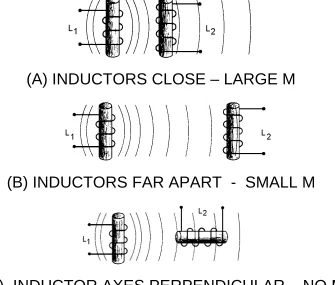
13. State the meaning of the term "coupled circuits." 14. State the meaning of the term "coefficient of coupling."
15. Given the inductance values of and the coefficient of coupling between two series-connected inductors, solve for mutual inductance, M.
16. Write the formula for the "total inductance" of two inductors connected in series-opposing. 17. Given the inductance values of and the mutual inductance value between two coils connected in
INDUCTANCE
The study of inductance presents a very challenging but rewarding segment of electricity. It is challenging in the sense that, at first, it will seem that new concepts are being introduced. You will realize as this chapter progresses that these "new concepts" are merely extensions and enlargements of
fundamental principles that you learned previously in the study of magnetism and electron physics. The study of inductance is rewarding in the sense that a thorough understanding of it will enable you to acquire a working knowledge of electrical circuits more rapidly.
CHARACTERISTICS OF INDUCTANCE
Inductance is the characteristic of an electrical circuit that opposes the starting, stopping, or a change in value of current. The above statement is of such importance to the study of inductance that it bears repeating. Inductance is the characteristic of an electrical conductor that OPPOSES CHANGE in CURRENT. The symbol for inductance is L and the basic unit of inductance is the HENRY (H). One henry is equal to the inductance required to induce one volt in an inductor by a change of current of one ampere per second.
You do not have to look far to find a physical analogy of inductance. Anyone who has ever had to push a heavy load (wheelbarrow, car, etc.) is aware that it takes more work to start the load moving than it does to keep it moving. Once the load is moving, it is easier to keep the load moving than to stop it again. This is because the load possesses the property of INERTIA. Inertia is the characteristic of mass which opposes a CHANGE in velocity. Inductance has the same effect on current in an electrical circuit as inertia has on the movement of a mechanical object. It requires more energy to start or stop current than it does to keep it flowing.
Q1. What is the basic unit of inductance and the abbreviation for this unit?
ELECTROMOTIVE FORCE (EMF)
You have learned that an electromotive force is developed whenever there is relative motion between a magnetic field and a conductor.
When a magnetic field moves through a stationary metallic conductor, electrons are dislodged from their orbits. The electrons move in a direction determined by the movement of the magnetic lines of flux. This is shown below:
The electrons move from one area of the conductor into another area. The area that the electrons moved from has fewer negative charges (electrons) and becomes positively charged. The area the electrons move into becomes negatively charged. This is shown below:
The difference between the charges in the conductor is equal to a difference of potential (or voltage). This voltage caused by the moving magnetic field is called electromotive force (emf).
The area from which electrons are moved becomes positively charged, while the area into which electrons are moved becomes negatively charged. The potential difference between these two areas is the electromotive force or emf.
Q2. An emf is generated in a conductor when the conductor is cut by what type of field?
SELF-INDUCTANCE
Even a perfectly straight length of conductor has some inductance. As you know, current in a conductor produces a magnetic field surrounding the conductor. When the current changes, the magnetic field changes. This causes relative motion between the magnetic field and the conductor, and an
electromotive force (emf) is induced in the conductor. This emf is called a SELF-INDUCED EMF because it is induced in the conductor carrying the current. The emf produced by this moving magnetic field is also referred to as COUNTER ELECTROMOTIVE FORCE (cemf). The polarity of the counter electromotive force is in the opposite direction to the applied voltage of the conductor. The overall effect will be to oppose a change in current magnitude. This effect is summarized by Lenz's law which states that: THE INDUCED EMF IN ANY CIRCUIT IS ALWAYS IN A DIRECTION TO OPPOSE THE EFFECT THAT PRODUCED IT.
Figure 2-2.—Self-inductance.
The direction of this induced voltage may be determined by applying the LEFT-HAND RULE FOR GENERATORS. This rule is applied to a portion of conductor 2 that is "lifted" and enlarged for this purpose in figure 2-2(A). This rule states that if you point the thumb of your left hand in the direction of relative motion of the conductor and your index finger in the direction of the magnetic field, your middle finger, extended as shown, will now indicate the direction of the induced current which will generate the induced voltage (cemf) as shown.
In figure 2-2(B), the same section of conductor 2 is shown after the switch has been opened. The flux field is collapsing. Applying the left-hand rule in this case shows that the reversal of flux MOVEMENT has caused a reversal in the direction of the induced voltage. The induced voltage is now in the same direction as the battery voltage. The most important thing for you to note is that the self-induced voltage opposes BOTH changes in current. That is, when the switch is closed, this voltage delays the initial buildup of current by opposing the battery voltage. When the switch is opened, it keeps the current flowing in the same direction by aiding the battery voltage.
This induced emf opposes the growth of the current and the growth of the magnetic field. If the increasing current had not set up a magnetic field, there would have been no opposition to its growth. The whole reaction, or opposition, is caused by the creation or collapse of the magnetic field, the lines of which as they expand or contract cut across the conductor and develop the counter emf.
Since all circuits have conductors in them, you can assume that all circuits have inductance.
However, inductance has its greatest effect only when there is a change in current. Inductance does NOT oppose current, only a CHANGE in current. Where current is constantly changing as in an ac circuit, inductance has more effect.
Q3. Define inductance.
Q4. What is meant by induced emf? By counter emf?
Q5. State Lenz's law.
Q6. What effect does inductance have (a) on steady direct current and (b) on direct current while it is changing in amplitude?
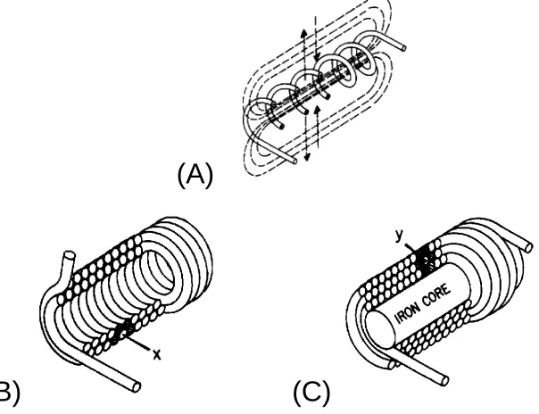
To increase the property of inductance, the conductor can be formed into a loop or coil. A coil is also called an inductor. Figure 2-3 shows a conductor formed into a coil. Current through one loop produces a magnetic field that encircles the loop in the direction as shown in figure 2-3(A). As current increases, the magnetic field expands and cuts all the loops as shown in figure 2-3(B). The current in each loop affects all other loops. The field cutting the other loop has the effect of increasing the opposition to a current change.
(A)
(B)
Figure 2-3.—Inductance.
(A)
(B)
Figure 2-4.—Inductor types and schematic symbols.
Factors Affecting Coil Inductance
There are several physical factors which affect the inductance of a coil. They include the number of turns in the coil, the diameter of the coil, the coil length, the type of material used in the core, and the number of layers of winding in the coils.
Inductance depends entirely upon the physical construction of the circuit, and can only be measured with special laboratory instruments. Of the factors mentioned, consider first how the number of turns affects the inductance of a coil. Figure 2-5 shows two coils. Coil (A) has two turns and coil (B) has four turns. In coil (A), the flux field set up by one loop cuts one other loop. In coil (B), the flux field set up by one loop cuts three other loops. Doubling the number of turns in the coil will produce a field twice as strong, if the same current is used. A field twice as strong, cutting twice the number of turns, will induce four times the voltage. Therefore, it can be said that the inductance varies as the square of the number of turns.
(A)
(B)
Figure 2-5.—Inductance factor (turns).
in the coil with the larger diameter. Actually, the inductance of a coil increases directly as the cross-sectional area of the core increases. Recall the formula for the area of a circle: A = πr2. Doubling the radius of a coil increases the inductance by a factor of four.
(A)
(B)
Figure 2-6.—Inductance factor (diameter).
The third factor that affects the inductance of a coil is the length of the coil. Figure 2-7 shows two examples of coil spacings. Coil (A) has three turns, rather widely spaced, making a relatively long coil. A coil of this type has few flux linkages, due to the greater distance between each turn. Therefore, coil (A) has a relatively low inductance. Coil (B) has closely spaced turns, making a relatively short coil. This close spacing increases the flux linkage, increasing the inductance of the coil. Doubling the length of a coil while keeping the same number of turns halves the value of inductance.
permeability has less reluctance to the magnetic flux, resulting in more magnetic lines of force. This increase in the magnetic lines of force increases the number of lines of force cutting each loop of the coil, thus increasing the inductance of the coil. It should now be apparent that the inductance of a coil increases directly as the permeability of the core material increases.
[image:55.612.146.448.462.694.2]
(A) AIR CORE (B) SOFT-IRON CORE
Figure 2-8.—Inductance factor (core material).
Another way of increasing the inductance is to wind the coil in layers. Figure 2-9 shows three cores with different amounts of layering. The coil in figure 2-9(A) is a poor inductor compared to the others in the figure because its turns are widely spaced and there is no layering. The flux movement, indicated by the dashed arrows, does not link effectively because there is only one layer of turns. A more inductive coil is shown in figure 2-9(B). The turns are closely spaced and the wire has been wound in two layers. The two layers link each other with a greater number of flux loops during all flux movements. Note that nearly all the turns, such as X, are next to four other turns (shaded). This causes the flux linkage to be increased.
(A)
(B)
(C)
A coil can be made still more inductive by winding it in three layers, as shown in figure 2-9(C). The increased number of layers (cross-sectional area) improves flux linkage even more. Note that some turns, such as Y, lie directly next to six other turns (shaded). In actual practice, layering can continue on through many more layers. The important fact to remember, however, is that the inductance of the coil increases with each layer added.
As you have seen, several factors can affect the inductance of a coil, and all of these factors are variable. Many differently constructed coils can have the same inductance. The important information to remember, however, is that inductance is dependent upon the degree of linkage between the wire
conductor(s) and the electromagnetic field. In a straight length of conductor, there is very little flux linkage between one part of the conductor and another. Therefore, its inductance is extremely small. It was shown that conductors become much more inductive when they are wound into coils. This is true because there is maximum flux linkage between the conductor turns, which lie side by side in the coil.
Q7.
a. List five factors that affect the inductance of a coil.
b. Bending a straight piece of wire into a loop or coil has what effect on the inductance of the wire?
c. Doubling the number of turns in a coil has what effect on the inductance of the coil?
d. Decreasing the diameter of a coil has what effect on the inductance of the coil?
e. Inserting a soft-iron core into a coil has what effect on the inductance of the coil?
f. Increasing the number of layers of windings in a coil has what effect on the inductance of the coil?
UNIT OF INDUCTANCE
As stated before, the basic unit of inductance (L) is the HENRY (H), named after Joseph Henry, the co-discoverer with Faraday of the principle of electromagnetic induction. An inductor has an inductance of 1 henry if an emf of 1 volt is induced in the inductor when the current through the inductor is changing at the rate of 1 ampere per second. The relationship between the induced voltage, the inductance, and the rate of change of current with respect to time is stated mathematically as:
where Eind is the induced emf in volts; L is the inductance in henrys; and ∆I is the change in current in
gradual because of the counter emf generated by the self-inductance of the coil. When the current starts to flow, the magnetic lines of force move outward from the coil. These lines cut the turns of wire on the inductor and build up a counter emf that opposes the emf of the battery. This opposition causes a delay in the time it takes the current to build up to a steady value. When the battery is disconnected, the lines of force collapse. Again these lines cut the turns of the inductor and build up an emf that tends to prolong the flow of current.
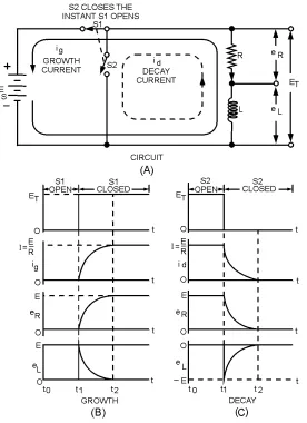
[image:57.612.173.449.196.576.2]A voltage divider containing resistance and inductance may be connected in a circuit by means of a special switch, as shown in figure 2-10(A). Such a series arrangement is called an LR series circuit.
Figure 2-10.—Growth and decay of current in an LR series circuit.
When switch S1 is closed (as shown), a voltage ES appears across the voltage divider. At this instant
the current will attempt to increase to its maximum value. However, this instantaneous current change causes coil L to produce a back EMF, which is opposite in polarity and almost equal to the EMF of the source. This back EMF opposes the rapid current change. Figure 2-10(B) shows that at the instant switch S1 is closed, there is no measurable growth current (ig), a minimum voltage drop is across resistor R, and
maximum voltage exists across inductor L.
As current starts to flow, a voltage (eR) appears across R, and the voltage across the inductor is
growth current (ig) is increased and consequently eR is increased. Figure 2-10(B) shows that the voltage
across the inductor (eL) finally becomes zero when the growth current (ig) stops increasing, while the
voltage across the resistor (eR) builds up to a value equal to the source voltage (ES).
Electrical inductance is like mechanical inertia, and the growth of current in an inductive circuit can be likened to the acceleration of a boat on the surface of the water. The boat does not move at the instant a constant force is applied to it. At this instant all the applied force is used to overcome the inertia of the boat. Once the inertia is overcome the boat will start to move. After a while, the speed of the boat reaches its maximum value and the applied force is used up in overcoming the friction of the water against the hull.
When the battery switch (S1) in the LR circuit of figure 2-10(A) is closed, the rate of the current
increase is maximum in the inductive circuit. At this instant all the battery voltage is used in overcoming the emf of self-induction which is a maximum because the rate of change of current is maximum. Thus the battery voltage is equal to the drop across the inductor and the voltage across the resistor is zero. As time goes on more of the battery voltage appears across the resistor and less across the inductor. The rate of change of current is less and the induced emf is less. As the steady-state condition of the current is approached, the drop across the inductor approaches zero and all of the battery voltage is "dropped" across the resistance of the circuit.
Thus the voltages across the inductor and the resistor change in magnitude during the period of growth of current the same way the force applied to the boat divides itself between the effects of inertia and friction. In both examples, the force is developed first across the inertia/inductive effect and finally across the friction/resistive effect.
Figure 2-10(C) shows that when switch S2 is closed (source voltage ES removed from the circuit), the
flux that has been established around the inductor (L) collapses through the windings. This induces a voltage eL in the inductor that has a polarity opposite to ES and is essentially equal to ES in magnitude.
The induced voltage causes decay current (id) to flow in resistor R in the same direction in which current
was flowing originally (when S1 was closed). A voltage (eR) that is initially equal to source voltage (ES) is
developed across R. The voltage across the resistor (eR) rapidly falls to zero as the voltage across the
inductor (eL) falls to zero due to the collapsing flux.
Just as the example of the boat was used to explain the growth of current in a circuit, it can also be used to explain the decay of current in a circuit. When the force applied to the boat is removed, the boat still continues to move through the water for a while, eventually coming to a stop. This is because energy was being stored in the inertia of the moving boat. After a period of time the friction of the water
overcomes the inertia of the boat, and the boat stops moving. Just as inertia of the boat stored energy, the magnetic field of an inductor stores energy. Because of this, even when the power source is removed, the stored energy of the magnetic field of the inductor tends to keep current flowing in the circuit until the magnetic field collapse.
Q8.
L/R Time Constant
The L/R TIME CONSTANT is a valuable tool for use in determining the time required for current in an inductor to reach a specific value. As shown in figure 2-11, one L/R time constant is the time required for the current in an inductor to increase to 63 percent (actually 63.2 percent) of the maximum current. Each time constant is equal to the time required for the current to increase by 63.2 percent of the difference in value between the current flowing in the inductor and the maximum current. Maximum current flows in the inductor after five L/R time constants are completed. The following example should clear up any confusion about time constants. Assume that maximum current in an LR circuit is 10 amperes. As you know, when the circuit is energized, it takes time for the current to go from zero to 10 amperes. When the first time constant is completed, the current in the circuit is equal to 63.2% of 10 amperes. Thus the amplitude of current at the end of 1 time constant is 6.32 amperes.
Figure 2-11.—L/R time constant.
During the second time constant, current again increases by 63.2% (.632) of the difference in value between the current flowing in the inductor and the maximum current. This difference is 10 amperes minus 6.32 amperes and equals 3.68 amperes; 63.2% of 3.68 amperes is 2.32 amperes. This increase in current during the second time constant is added to that of the first time constant. Thus, upon completion of the second time constant, the amount of current in the LR circuit is 6.32 amperes + 2.32 amperes = 8.64 amperes.
During the third constant, current again increases:
During the fifth time constant, current increases as before:
Thus, the current at the end of the fifth time constant is almost equal to 10.0 amperes, the maximum current. For all practical purposes the slight difference in value can be ignored.
When an LR circuit is deenergized, the circuit current decreases (decays) to zero in five time constants at the same rate that it previously increased. If the growth and decay of current in an LR circuit are plotted on a graph, the curve appears as shown in figure 2-11. Notice that current increases and decays at the same rate in five time constants.
The value of the time constant in seconds is equal to the inductance in henrys divided by the circuit resistance in ohms.
The formula used to calculate one L/R time constant is:
Q9. What is the formula for one L/R time constant?
Q10.
a. The maximum current applied to an inductor is 1.8 amperes. How much current flowed in the inductor 3 time constants after the circuit was first energized?
b. What is the minimum number of time constants required for the current in an LR circuit to increase to its maximum value?
c. A circuit containing only an inductor and a resistor has a maximum of 12 amperes of applied current flowing in it. After 5 L/R time constants the circuit is opened. How many time
constants is required for the current to decay to 1.625 amperes?