Fast Geometric Transformations on Quantum
Images
Phuc Q. Le
∗, Abdullahi M. Iliyasu
†, Fangyan Dong
‡, Kaoru Hirota
§Abstract—Circuits to achieve geometric trans-formations including two-point swapping, flip, co-ordinate swapping, orthogonal rotations and their variants on N-sized quantum images are proposed based on the basic quantum gates; NOT, CNOT and Toffoli gates. The complexity of the circuits is O(log2N) for two-point swapping and O(logN) for flip, co-ordinate swapping and orthogonal rotations. The results indicate that local operations like two-point swapping are slower than global operations like flip, co-ordinate swapping, and orthogonal rotations in quantum image processing. This is in contrast to performing such operations in classical image process-ing where the local operations are faster. All the proposed transformations are confirmed by simula-tion on a classical computer. With their low com-plexity, these geometric transformations can be used as the major components to build circuits for other applications on quantum images.
Keywords: quantum computation, image processing, geometric transformation, complexity, quantum cir-cuit
1
Introduction
In recent years quantum computation and quantum infor-mation have generated so much interest especially with the prospect of employing its insights to empower our knowledge on information processing. In 1994 Peter Shor[16] discovered a quantum algorithm to factor integer numbers in polynomial time. This was closely followed by Grover’s quadratic speed-up database search algorithm[7]
∗Corresponding author. Department of Computational Intel-ligence and Systems Science, Interdisciplinary Graduate School of Science and Engineering, Tokyo Institute of Technology, G3-49, 4259 Nagatsuta, Midoriku, Yokohama 226-8502, Japan. Tel.: +81-45-924-5686/5682, Fax: +81-45-924-5676, E-mail: [email protected]
†Department of Computational Intelligence and Systems Sci-ence, Interdisciplinary Graduate School of Science and Engineering, Tokyo Institute of Technology, G3-49, 4259 Nagatsuta, Midoriku, Yokohama 226-8502, Japan. E-mail: [email protected]
‡Department of Computational Intelligence and Systems Sci-ence, Interdisciplinary Graduate School of Science and Engineering, Tokyo Institute of Technology, G3-49, 4259 Nagatsuta, Midoriku, Yokohama 226-8502, Japan. E-mail: [email protected]
§Department of Computational Intelligence and Systems Sci-ence, Interdisciplinary Graduate School of Science and Engineering, Tokyo Institute of Technology, G3-49, 4259 Nagatsuta, Midoriku, Yokohama 226-8502, Japan. E-mail: [email protected]
on the quantum computation model. These results and the unavoidbly inefficient simulation of quantum physics on classical computers[5] provide the solid evidence of the strength of quantum computers over classical ones.
In quantum circuit models of computation, designing such circuits is necessary to realize and analyze any quan-tum algorithm. It is well known that any unitary oper-ation or quantum algorithm can be decomposed into a circuit consisting a succession of basic unitary gates that act on one or two qubits only. Many elementary gates in-cluding single qubit gates, controlled-NOT or CNOT and Toffoli gates for quantum computation was introduced in [1]. Physical implementations of the qubit and these gates are available from many approaches [14], [15,Chapter 7].
One of the most active fields in quantum computation and information is quantum image processing. Quantum signal processing transformations such as Fourier[15], wavelet[6], and discrete cosine[8],[17] are proven to be more efficent than their classical versions. Using these ef-fecient operations for image processing applications pre-viously inefficient approaches involving classical opera-tions are realizable.[2]. Parallelism in quantum computa-tion can speed up many image processing tasks which have characteristics of parallelism[12]. Some concepts of quantum images have been proposed like Qubit Lat-tice[18],[19], Real Ket[9] and Flexible Representation of Quantum Images(FRQI)[12] in order to make the connec-tion between quantum algorithms and image processing applications. Some impossible processing operations on quantum computers[10] indicate the fundamental differ-ence between quantum and classical operations. To de-sign fast algorithms for quantum image processing, we need to extend our knowledge on fundamental and ef-ficient operations since only few of them are known as mentioned ealier.
Fast geometric transformations such as the two-point swapping, flip, co-ordinate swapping, orthogonal rota-tions and their variants for quantum images, specifically those based on the FRQI representation, are proposed using the basic quantum gates, NOT, CNOT and Tof-foli gates. For anN-sized image, the detailed analysis of quantum circuits show that the complexity is O(log2N) for two-point swapping and O(logN) for the other op-erations. The two-point swapping operation is powerful
IAENG International Journal of Applied Mathematics, 40:3, IJAM_40_3_02
since it can be built by arbitrary geometric transforma-tions, but it is slower than the others. This fact is in constrast to their performance in classical versions but it agrees with the parallelism characteristic of quantum computation. In terms of their effect on images, the lo-cal transformations are slower than global ones among quantum image processing operations. The orthogonal rotations are the first examples of applying a succession of quantum transformations to create new applications on quantum image processing. The experiments by sim-ulation of the quantum operations on classical computers confirm the feasibility of all of the proposed transforma-tions. The fast geometric transformations can be used as efficient blocks to design other quantum image processing algorithms.
The rest of the paper is organized as follows. We start with a brief overview of the the flexible representation of quantum images (FRQI) and the general framework for geometric transformations on FRQI. In subsequent sections the various definitions, lemmas, theorems and proofs for the two-point swap gate, flip gate, co-ordinate swapping, orthogonal rotation gates, and their variants are presented. Experimental results to prove the realiza-tion of the geometric transformarealiza-tions and their feasibility are discussed in section 6. Discussion of future work and concluding remarks are found in section 7.
2
Representation of quantum images and
general framework of geometric
trans-formations
We start by introducing the notations used in this paper which has been used in a wide range of quantum compu-tation literature[15]. The state of a quantum system is described as a vector in a Hilbert space which is called a ket in Dirac or quantum mechanical notation. The ket and its adjoint, bra, notations are defined as follows;
|ui=
u0 u1 .. .
un−1
, ui∈C, i= 0,1, . . . , n−1,
hu|=|ui†=
[
u†0u†1 . . . u†n−1
]
.
The notation for the tensor or Kronecker product, ⊗, is used to express the composition of quantum systems. The tensor product of two matrices A and B is defined as follows; A=
a11 a12 . . . a1m a21 a22 . . . a2m
..
. ... . .. ...
an1 an2 . . . anm
, B=
b11 b12 . . . b1q b21 b22 . . . b2q
..
. ... . .. ...
bp1 bp2 . . . bpq
,
A⊗B=
a11B a12B . . . a1mB a21B a22B . . . a2mB
..
. ... . .. ...
an1B an2B . . . anmB
, where
aijB=
aijb11 aijb12 . . . aijb1q aijb21 aijb22 . . . aijb2q
..
. ... . .. ...
aijbp1 aijbp2 . . . aijbpq
,∀i, j.
The short notation for tensor product |ui ⊗ |vi of two vectors or two kets, |uiand |vi, is |uvi or |ui|viand we useA⊗n =A⊗A⊗ · · · ⊗Ato denote the tensor product
of matrixAfor n times.
The representation of quantum images, which enables the application of unitary transformations, was proposed in [12]. This proposal integrates information about colors and their correspoding positions in an image into a quan-tum state having its formular as in (1)
|I(θ)i= 1 2n
22n∑−1 k=0
|cki ⊗ |ki, (1)
|cki= cosθk|0i+ sinθk|1i, (2)
θk∈
[
0,π
2
]
, k= 0,1, . . . ,22n−1, (3)
where ⊗ is the tensor product notation, |0i, |1i are 2-D computational basis quantum states, |ki, k = 0,1, . . . ,22n−1 are 22n-D computational basis quantum state and θ = (θ0, θ1, . . . , θ22n−1) is the vector of angles
encoding colors. There are two parts in the FRQI repre-sentation of an image;|ckiand|kiwhich encode informa-tion about the colors and their corresponding posiinforma-tions in the image, respectively.
For the 2-D images, the position information|kiincludes two parts, the vertical and horizontal co-ordinates. In 2n -qubit systems for preparing quantum images, or 2n-qubit images, the vector|ki
|ki=|yi|xi=|yn−1yn−2. . . y0i|xn−1xn−2. . . x0i,
xi, yi∈ {0,1},
for every i= 0,1, . . . , n, which encodes the first n-qubit
yn−1,yn−2,. . .,y0the vertical location and the secondn
-qubitxn−1,xn−2,. . .,x0encodes the horizontal location
information as shown in Fig. 1.
IAENG International Journal of Applied Mathematics, 40:3, IJAM_40_3_02
Figure 1: Vertical and horizontal coordinates encoded in qubits
Geometric transformations are the operations which are peformed based on the geometric information of images, i.e., information about position of every point in the image. Therefore, these transformations, GI, on FRQI quantum images can be defined as in (4),
GI(|I(θ)i) = 1 2n
22n−1
∑
k=0
|cki ⊗G(|ki), (4)
where G(|ki) for k = 0,1, . . . ,22n−1 are the unitary
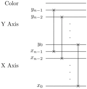
transformations performing geometric exchanges based on the vertical and horizontal locations. The performance of the geometric transformations on quantum images,GI, is based on the function, G, on the computational basis vectors. The general structure of circuits for geometric transformations on FRQI images is shown in Fig.2.
|I(θ)i G(|I(θ)i)
Color
yn−1
G yn−2
Y Axis .
. .
y0
xn−1
xn−2
X Axis .
. .
x0
Figure 2: General circuit design for geometric transfor-mations on quantum images
3
Two-point swapping operations
In classical image processing two-point swapping is one of the fundamental operations. However, this kind of
op-eration has not been introduced in quantum image pro-cessing because of the lack of a suitable representation for the quantum image. Based on the FRQI representation we can construct the quantum circuit for the two-point swapping operations. But let us start with the definition of the two-point swapping operation.
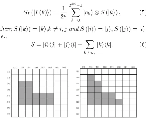
Definition 1. The two-point swapping operation on FRQI quantum images between two positions i, j is the operationSI which when applied on|I(θ)iin (1) produces the output of the following form
SI(|I(θ)i) = 1 2n
22n−1
∑
k=0
|cki ⊗S(|ki), (5)
whereS(|ki) =|ki,k6=i, jandS(|ii) =|ji, S(|ji) =|ii, i.e.,
S=|iihj|+|jihi|+ ∑
k6=i,j
[image:3.595.310.549.215.411.2]|kihk|. (6)
[image:3.595.75.244.449.658.2]Figure 3: An example of two-point swapping operation
Figure 3 shows an example of two-point swapping oper-ation in which the operoper-ation swaps the points|110i|110i and|011i|010i. From the definition 1 we can reduce the operation SI on the FRQI images |I(θ)i to the oper-ation S(|ki), for k = 0,1, . . . ,22n −1. For general-ization, we will discuss the performance of S over the superposition of |ki, for k = 0,1, . . . ,22n −1, that is
|Ki=∑kk=0=22n−1ak|ki.
In the quantum circuit model, a complex transform is broken down into simpler gates, i.e., single qubit, controlled two and three qubit gates, such as NOT, Hadamard, CNOT, and Toffoli gates which are shown in Fig. 4.
Note 1. The notation Cm−2(σx) has been used for the
generalized control NOT gates, wherem−2indicates the number of control wires of the gates. Corollary 7.3 and Corollary 7.4 in [1] show that these gates can be con-structed by Toffoli gates on a m-qubit circuit (m ≥ 5) and the number of Toffoli gates is8(m−5)whenm≥7.
The examples for Note 1 with m = 5 and m = 7 are shown in Fig. 5 and Fig. 6 respectively. These results are used in the proof of Lemma 2.
IAENG International Journal of Applied Mathematics, 40:3, IJAM_40_3_02
NOT Gate
α|0i+β|1i X β|0i+α|1i
Hadamard Gate
α|0i+β|1i H α(|0i√+|1i)
2 +β
(|0i−|√ 1i) 2
Controlled NOT or CNOT Gate
|Ai • |Ai
|Bi |A⊕Bi
Toffoli Gate
|Ai • |Ai
|Bi • |Bi
[image:4.595.98.271.73.316.2]|Ci |AB⊕Ci
Figure 4: NOT, Hadamard, CNOT, and Toffoli gates.
• •
• • •
• = • •
• • •
[image:4.595.334.521.84.179.2]
Figure 5: The C3(σ
x) can be constructed by 4 Toffoli
gates on a 5-qubit circuit.
Lemma 1. The two-point swapping operation S for po-sitions i,j as in (4) can be constructed by NOT, CNOT and Toffoli gates.
Figure 7 shows an example of two-point swapping circuit, that can be built from Toffoli gates.
Proof. We prove the lemma by induction.
• For n = 0: it is trivial since only one point in the FRQI image exists.
• For n = 1: the FRQI images include four points, encoded as |00i, |01i, |10i, |11i. There are six possible two-point swapping operations,S, between these four positions. The superposition of |ki, for k = 0,1, . . . ,22n − 1, in this case is |Ki =
∑k=3
k=0ak|ki.These operations can be constructed by
NOT and CNOT gates as in Fig. 9.
• For n = 2: the FRQI images contain 16 points,
|0000i,|0001i, . . . ,|1111i. These points can be
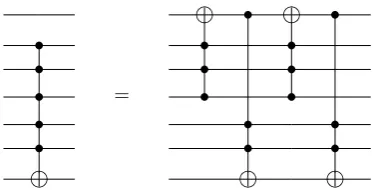
• •
• • •
• • •
• = • •
• • •
• • •
Figure 6: The C5(σx) can be constructed by 4 C3(σx)
gates on a 7-qubit circuit.
Swapping between|111011iand|101111i
• • • • • •
y2 • • • • • • • • •
y1 • • •
y0 • • • = • • • • • •
x2 • • • • • •
x1 • • • • • • • • •
x0 • • • • • • • • •
A B C A B C
Figure 7: Example of two-point swapping operation be-tween|111011iand|101111i. EachC5(σX) in groups A,
B, C can be simulated by 4 C3(σX) as in Fig. 7 and again each C3(σX) can be simulated by 4 Toffoli gates as in Fig. 6. Therefore, the swapping operation can be simulated by 16 Toffoli gates.
vided into four blocks in the form|0y00x0i,|0y01x0i,
|1y00x0i and |1y01x0i, each block includes four
points. If the points at positions encoded by |ii =
|yi
1yi0xi1x0ii, |ji=|y j 1y
j 0x
j 1x
j
0iare in the same block,
which means yi1 = yj1 and xi1 = xj1,we can use the circuits explained in the casen= 1 for they0andx0
qubits with the controlled conditions from they1and x1 qubits, which indicate the location of the block,
to achieve the operation. In doing that, we use one two-point swapping on a 2-qubit system with two controlled conditions. If the points are not in the same block, we first swap the point in position|ji=
|yj1yj0xj1xj0iwith a point p=|yi 1y
j 0xi1x
j
0iin the same
block with the point in position|ii=|yi
1y0ixi1xi0iby
using the circuits explained in the case of n= 1 for the qubity1and qubitx1under the controlled
condi-tion from they0andx0qubits . Secondly we perform
two-point swapping operation for the pointsi,jsince they are in same block. Finally, we use two-point swapping on the qubit y1 and qubit x1to exchange
the points j, p. In short, we use three two-point
IAENG International Journal of Applied Mathematics, 40:3, IJAM_40_3_02
[image:4.595.314.545.274.410.2] [image:4.595.76.263.363.435.2]swapping on a 2-qubit system with two controlled conditions to complete a two-point swapping on a 4-qubit system wheni,jare in different blocks. There-fore, two-point swapping, S, in the casen = 2 can be constructed by NOT, CNOT and Toffoli gates.
• For n > 2: assume that we have the two-point swapping circuits constructed by NOT, CNOT and Toffoli gates for n−1 FRQI images. We denote the computational basis of the 2n-qubit system by
|yn−1yn−2. . . y0xn−1xn−2. . . x0i. The n FRQI
im-ages can be divide into 4 subimim-ages in form
|0yn−2. . . y00xn−2. . . x0i,
|0yn−2. . . y01xn−2. . . x0i,
1yn−2. . . y00xn−2. . . x0i,
and
|1yn−2. . . y01xn−2. . . x0i.
If the points at positions i, j encoded by
|ii = |yin−1yin−2. . . yi0xin−1xin−2. . . xi0i and |ji =
|yjn−1ynj−2. . . y0jxjn−1xjn−2. . . xj0i are in the same block, which meansyi
n−1 =y j
n−1 andxin−1 =x j n−1,
we can use the circuits in the casen−1 size with two controlled conditions from theyn−1andxn−1 qubits
to achieve the operation. If the points are not in the same block, we first swap the pointj in the position encoded by |ji = |ynj−1yjn−2. . . y0jxjn−1xjn−2. . . xj0i
with the point p at the position encoded by |pi =
|yi n−1y
j n−2. . . y
j 0x
i n−1x
j n−2. . . x
j
0i by using the
cir-cuits in the case of n = 1 size for the qubit yn−1
and qubit xn−1 with 2(n−1) controlled condtions
fromyk, xkqubits (k= 0,1, . . . , n−2). Secondly we
perform two-point swapping operation for the points
i, j as explained in the case when they are in same block. Finally, we use two-point swapping on the qubityn−1and qubit xn−1to exchange the pointsj, p. In short, the two-point swappings,S, in the case
n >2 can be constructed by NOT, CNOT and Tof-foli gates.
Remark 1. With the swapping method explained in Lemma 2, the circuit that contains the largest number of basis gates for swapping two points encoded by|ii and
|jionn-size FRQI images is the circuit for the swapping between |0i and|22n−1i.
Proof. By inspection.
Theorem 1. The complexity of two-point swapping op-eration on n-size FRQI images (n≥2) isO(n2).
swapping|00iand|01i
y0 X • X
x0
swapping|00iand|10i
y0
x0 X • X
swapping|00iand|11i
y0 X ×
x0 X ×
swapping|01iand|10i
y0 ×
x0 ×
swapping|01iand|11i
y0
x0 •
swapping|10iand|11i
y0 •
x0
Figure 8: Swapping on 2-qubit systems.
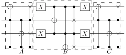
Proof. Using the Remark 1, the complexity of two-point swapping operation on n-size FRQI images in the worst case is to swap|0iand|22n−1i. There are three groups,
A, B, C in the circuit for such swapping, the exam-ple of n = 2 is explained in Fig. 10. The block A transforms from |11. . .1i|11. . .1i to |0. . .01i|0. . .01i, group B swaps |0. . .01i|0. . .01i and |0. . .00i|0. . .00i and finally the group C transforms from|0. . .01i|0. . .01i to |11. . .1i|11. . .1i. The group A can be divided into n−1 steps to transform from |11. . .1i|11. . .1i to
|01. . .1i|01. . .1iin first step, then from|01. . .1i|01. . .1i to|001. . .1i|001. . .1iin the second step, and so on. Each step in group A contains 2 C2n−2(σX) , 3 C2n−1(σX)
and NOT gates. The group C transformation is similar to group A. That of group B contains 2 C2n−2(σX) , 3 C2n−1(σX) gates and NOT gates. Using Note 1, the
IAENG International Journal of Applied Mathematics, 40:3, IJAM_40_3_02
number of Toffoli gates to simulate 2(2n−1)C2n−2(σX) and 3(2n−1) C2n−1(σX) gates is O(n2). Each Toffoli gate can be simulated by 9 single qubit and 6 CNOT gates as in Fig. 5 and the number of NOT gates in the circuit is 4(n−1). Hence, the total number of basis gates in the circuit isO(n2).
× X • • • X ×
• • • × • • •
× X • • • X ×
• • • × • • •
A B C
_ _ _ _
_ _ _ _
_ _ _ _ _ _ _ _ _
_ _ _ _ _ _ _ _ _
_ _ _ _
[image:6.595.364.470.112.235.2]
_ _ _ _
Figure 9: The two-point swapping operation can be di-vided into three groups A, B, C.
4
Flip and co-ordinate swap circuits
[image:6.595.69.271.164.253.2]Flip and coordinate swap are fundamental operations in classical image processing. The flipping operation on FRQI quantum images is defined as follows;
Figure 10: Image flipping along X axis.
Figure 11: Image flipping along Y axis.
Definition 2. The flipping operations on FRQI quantum images along the X and Y axes are the operation FIX andFIY which when applied on|I(θ)iin (1) produces the outputs of the following form;
FIX(|I(θ)i) =
1 2n
22n−1
∑
k=0
|cki ⊗FX(|ki), (7)
FIY(|I(θ)i) =
1 2n
22n−1
∑
k=0
|cki ⊗FY (|ki), (8)
where|ki=|yi|xiand
FX(|yi|xi) =|y¯i|xi, (9)
FY (|yi|xi) =|yi|x¯i, (10)
|xi=|xn−1xn−2. . . x0i,
|yi=|xn−1xn−2. . . x0i,
|x¯i=|x¯n−1x¯n−2. . .x¯0i,
|y¯i=|yn¯ −1yn¯ −2. . .y¯0i,
¯
xi= 1−xi,y¯i = 1−yi,
i= 0,1, . . . , n−1.
Theorem 2. The complexity of the flipping operations FX andFY as in (7) and (8) isO(n)on 2n-qubit FRQI quantum images. quantum images.
Proof. The quantum circuits for FX and FY are
constructed by using n NOT gates on n qubits
yn−1, yn−2, . . . , y0andxn−1, xn−2, . . . , x0respectively. In
mathematical form, the circuits are expressed by the ten-sor product ofnidentityIandnPauliX matrcies. Con-sequently, the operations are defined as follows;
FX=X⊗n⊗I⊗n, (11)
and
FY =I⊗n⊗X⊗n. (12)
On FRQI quantum images the co-ordinate swapping op-erations are defined as follows;
Definition 3. The co-ordinate swapping operation is the operation CI which when applied on |I(θ)i in (1) pro-duces the outputs of the following form;
CI(|I(θ)i) = 1 2n
22n−1
∑
k=0
|cki ⊗C(|ki), (13)
where|ki=|yxiand
C(|yxi) =|xyi. (14)
Theorem 3. The complexity of the co-ordinate swapping operation CI as in (13) on 2n-qubit FRQI quantum im-ages isO(n).
IAENG International Journal of Applied Mathematics, 40:3, IJAM_40_3_02
[image:6.595.61.277.376.587.2]FY
Color
yn−1 yn−2
.
Y Axis .
.
y0 xn−1 X
xn−2 X
.
X Axis .
.
x0 X
FX
Color
yn−1 X
yn−2 X
.
Y Axis .
.
y0 X xn−1 xn−2
.
X Axis .
.
[image:7.595.342.492.76.230.2]x0
Figure 12: The circuit design ofFX andFY.
Proof. A swap gate, which is composed by 3 CNOT gates as shown in the Fig. 13, is used to build the circuit for C. The application of n swnapping gates, Gi, on
the yi and xi qubits for every i = 0,1, . . . , n−1 is the
coordinate swapping circuit. Therefore, the operationC
can be constructed by 3nCNOT gates. That means the complexity of the circuits isO(n).
Swap Gate
× • •
=
× •
Figure 13: Swap gate can be built by three CNOT gates.
Color
yn−1 × yn−2 ×
Y Axis .
. .
y0 ×
xn−1 × xn−2 ×
X Axis .
. .
x0 ×
Figure 14: Co-ordinate swapping circuit.
5
Orthogonal rotation circuits and other
geometric transformations
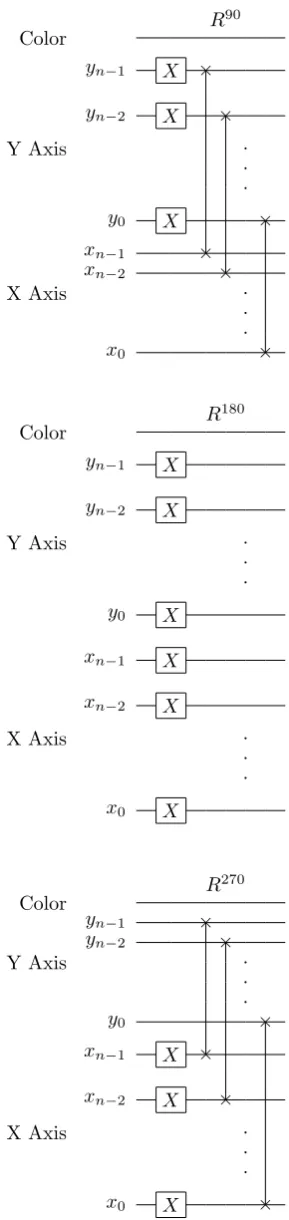
Image orthogonal rotations are the image rotations with the angles 900, 1800and 2700. The results from math-ematics point out that the orthogonal rotations can be achieved by using flipping and coordinate swapping op-erations.
Definition 4. The orthogonal rotation operations on FRQI quantum images are the operationsR90
I ,R180I ,RI270 which when applied on |I(θ)iin (1) produces the outputs of the following form;
RaI(|I(θ)i) =
1 2n
22n−1
∑
k=0
(cosθk|0i+ sinθk|1i)⊗Ra(|ki),
(15) wherea∈ {90,180,270},|ki=|yxiand
R90(|yxi) =|xy¯i, (16)
R180(|yxi) =|y¯x¯i, (17)
R270(|yxi) =|xy¯ i. (18)
Theorem 4. The complexity of the orthogonal rotations, R90,R180, andR270, on2n-qubit FRQI quantum images isO(n).
Proof. The rotations can be built from flipping and co-ordinate swapping operations as
R90=CFX, (19)
R180=FYFX, (20)
R270=CFY. (21)
Other geometric transformations can be constructed from the above mentioned operations using the method that was used to achieve orthogonal rotations from flips and co-ordinate swappings. For example, we can consider
IAENG International Journal of Applied Mathematics, 40:3, IJAM_40_3_02
[image:7.595.82.247.657.721.2]R90
Color
yn−1 X ×
yn−2 X ×
Y Axis .
. .
y0 X ×
xn−1 ×
xn−2 ×
X Axis .
. .
x0 ×
R180
Color
yn−1 X
yn−2 X
Y Axis .
. .
y0 X
xn−1 X
xn−2 X
X Axis .
. .
x0 X
R270
Color
yn−1 ×
yn−2 ×
Y Axis .
. .
y0 ×
xn−1 X ×
xn−2 X ×
X Axis .
. .
[image:8.595.84.229.96.708.2]x0 X ×
Figure 15: Rotation Circuits.
transformations that have effect on sub-areas of an im-age, lets say flip along X axis for right-half of the image. This kind of operations requires extra information to in-dicate the sub-area in which the original transformations are actually performed. From the quantum circuit model, the extra information about the sub-area is expressed in the restricting conditions used to target the sub area’s by using controlled quantum gates, for example CNOT or Toffoli gate. In the example of flipping the right-half of the image along the X axis, the sub-area is the right-half and the original transformation is flip along X axis. The right-half area of ann-size image contains positions in the form |yi|1xn−2. . . x0i. We use a control
condi-tion from the qubit xn and a flip along X axis, which includes n NOT gates as presented in section 4, in the quantum circuit design of the transformation. Therefore, the transformation can be built fromnCNOT gates. Us-ing this strategy we can create many other variants from the original proposals of flip, co-ordinate swapping and orthogonal rotations.
6
Experiments of geometric
transforma-tions on quantum images
The storage and retrieval of quantum images in FRQI representation was presented in [12]. The experiments involved simulating the quantum images on a classical computer. These simulations use linear algebra in which the complex vectors are the quantum image states and the unitary matrices are the image processing operations. The final step in these simulations is measurement which converts the quantum information into the classical infor-mation in form of probability distributions. Extracting and analyzing the distributions gives the information for retrieving the transformed images.
Using matrix operations, however, is not practical since the size of unitary matrices increases exponentially with the number of qubits. In addition, the main information for simulation is about the images only and not about the operations. In order to increase the size of images in the program memory we focus on the main information of the FRQI representation; color and positions. Therefore, for every point in the simulation of FRQI quantum images there are two arrays, named COLOR for colors|ckiand
POS for positions|ki. The performance of the geometric transformations is on the POS array only and the new quantum image after the transformations is obtained by combining the POS array with its corresponding COLOR array. Table 1 shows the number of elements in each array forn-qubit (2n-size) FRQI images. The simulation
program used Matlab 2008a on a computer with Intel Core 2 Quad, 2.36 GHz CPU, 4GB Ram.
The proposed geometric transformations including flip, co-ordinate swap, orthogonal rotation, and the restricted operation to flip the right-half of the original image along
IAENG International Journal of Applied Mathematics, 40:3, IJAM_40_3_02
Table 1: Sizes of COLOR, POS arrays. COLOR POS
Rows 2n 2n
Columns 1 n
Data Type double 0,1
X axis are confirmed by simulation as shown in the Fig. 16.
a. Original image b. Flip along X axis
c. Flip along Y axis d. Co-ordinate Swap
e. 90o rotation f. 180o rotation
[image:9.595.54.248.202.523.2]g. 270orotation h. Flip of the right-half
Figure 16: Confirmation of proposed gemetric transfor-mations.
For each geometric transformation on an FRQI image, the program scans and edits the content of every row in the POS array. When dealing with large images, such as 20-qubit images, scanning linearly through the POS array is not efficient. Consequently, the program uses parallel approach to speed up the whole simulation. The sim-ulation time of NOT, CNOT, SWAP, and Toffoli gates is indicated in Table 2 and Fig. 17. The interdepen-dence of the running time with the size of images shows the limitation of the simulation of quantum image pro-cessing. For geometric transformations, the running time increases with both the number of simple gate and the size of the images as shown in Table 3. This information is useful for designing new quantum image processing op-erations based on the basic gates.
Table 2: Running time (seconds) for basic gates; NOT, CNOT, SWAP, and Toffoli gates.
[image:9.595.337.515.202.365.2]No. of qubits NOT CNOT SWAP Toffoli 14 0.22 0.26 0.42 0.23 16 0.33 0.37 0.85 0.27 18 0.72 0.96 2.54 0.48 20 2.20 3.34 9.50 1.40 22 8.05 12.94 38.02 5.45
Figure 17: Simulation running time of basic gates
[image:9.595.320.533.487.581.2]The next experiment is a simple image processing task. In this experiment the 512×512 input image includes four smaller 256×256 images as shown on the left side of Fig. 18. The goal is to rotate three out of the four smaller
Figure 18: The input image (left side) and the output image (right side) using in the second experiment.
images to make all the images upright and change their relative position in the input image. The output image is shown on the right side of Fig. 18.
The quantum circuit to perform such a task is shown in Fig. 19. In this circuit, there are 8 wires for X and Y axes to encode the dimensions of each of the four smaller images. The two extra wires one for each axis are used to encode the smaller 256×256 images relative to the larger 512×512 image. The circuit comprises of two blocks of
IAENG International Journal of Applied Mathematics, 40:3, IJAM_40_3_02
Table 3: Running time (seconds) of geometric transfor-mations
No. of qubits Flip Swap Rotation Others
14 1.10 1.95 2.46 6.32
16 1.51 5.56 6.80 15.40 18 5.11 21.47 25.56 56.60 20 20.57 93.61 116.30 243.51 22 90.11 428.52 517.09 1116.9
geometric transformations R90 and restricted version of R270. The R90 block rotates the whole image 90o
clock-wise. Finally, the upper-left 256×256 smaller image ob-tained from the previous step is rotated 270o clockwise.
This is achieved by imposing additional restrictions to target and restrict the operation to that area only as seen in Fig. 19. To realize the desired output image, a middle stage is obtained after rotating the entire 512×512 im-age using the R90 operation. The output image of this
stage is shown in Fig. 20. The block has two control wires onR270 from the extra wires which provide the informa-tion to restrict the performance ofR270on the upper-left conner.
Color Y Axis (8 wires) /
R90
R270
X Axis (8 wires) /
Extra Y
[image:10.595.51.223.380.461.2]Extra X
Figure 19: Quantum circuit for the application compris-ing two blocks of geometric transformationsR90and re-stricted version ofR270.
Figure 20: The image obtained from the input image after the first step.
As proven in 5, the total number of basic gates in the quantum circuit is linear with the number of qubits used to express the input image i.e. 18 qubits. To achieve the same operation, an operation has to examine each pixel in the input image and move it to a new position in the
output image, that means the complexity is equal to the size of the input image, in this case 29 ×29. This re-sult shows the efficiency of geometric transformations on FRQI quantum images over similar operations on classi-cal computers.
7
Conclusions
Geometric transformations on quantum images including two-point swapping, flip, co-ordinate swapping, and or-thogonal rotations with low complexity are proposed us-ing basic gates like NOT, CNOT, and Toffoli gates. This low complexity agrees with results for similar transfor-mations which are also fast on classical images. The pro-posed operations can be divided into local and global op-erations according to their effect on the quantum images. From this point of view, the local operations are found to be slower than the global operations resulting from the parallelism of quantum computation. This is in con-trast to classical image processing transformations. Al-though arbitrary geometric transformations can be con-structed by two-point swapping operations, the complex-ity of this method is high since we are using local opera-tions, especially for those geometric transformations that have global effect. Meanwhile, the global operations like flip, co-ordinate swapping, and orthogonal rotations are faster, that means we should think about these opera-tions before using local operaopera-tions in the design process of quantum circuits. The simulation experiments confirm all the proposed transformations. Based on the results presented in 3-5, we can restrict the basic operations on our simulation system to NOT, CNOT, and Toffoli gates. The memory space and processing speed, posed some un-avoidable problems in the simulation of quantum images and their processing operations on classical computers. In order to improve the performance of the simulation system, our strategy was to reduce memory space by fo-cusing on the effect of transformations on quantum im-ages instead of the transformations themselves. During the analysis of the simulation system in 6, we found out that the parallelism of transformations on quantum im-ages can be translated directly to the parallel computing methods.
As for future work, the results in this paper will be ex-tended towards the following directions. As discussed in 3, the two-point swapping operators can be used to con-struct arbitrary geometric transformations. Since their complexity is O(log2N), we should use them as less as possible and use more operations like flip, co-ordinate swapping and rotations whose complexity is O(logN). Secondly, the problem of designing the quantum circuits with low complexity for arbitrary geometric transforma-tions is still open and needs to be investigated using the group theory point of view. Thirdly, using geometric transformations in other applications of quantum image processing appears very promising, for example
applica-IAENG International Journal of Applied Mathematics, 40:3, IJAM_40_3_02
[image:10.595.126.214.532.624.2]tions in quantum image watermarking, quantum image cryptography can be done by hiding secret information in the design of quantum circuits. Combining with the color related operations [18], the geometric operations can be used as major components to build full quantum image processing applications.
References
[1] Barenco, A., Bennett, C. H., Cleve, R., DiVincenzo, D. P., Margolus, N., Shor, P., Sleator, T., Smolin, J. A., Weinfurter, H., “Elementary gates for quantum computation,”Phys. Rev. A52, 3457, 1995.
[2] Beach, G., Lomont, C., Cohen, C., “Quantum image processing (quip),”Proc. of Applied Imagery Pattern Recognition Workshop, pp.39-44, 2003.
[3] Caraiman, S., Manta, V. I., “New applications of quantum algorithms to computer graphics: the quantum random sample consensus algorithm,” Proc. of the 6th ACM conference on Computing fron-tier, pp. 81-88, 2009.
[4] Curtis, D., Meyer, D. A., “Towards quantum tem-plate matching,” Proc. of the SPIE, Vol. 5161. pp. 134-141, 2004.
[5] Feynman, R. P., “Simulating physics with comput-ers,” International Journal of Theoretical Physics, 21(6/7). pp. 467-488, 1982.
[6] Fijany, A., Williams, C. P., “Quantum wavelet transform: fast algorithm and complete circuits,”
arXiv:quantph/9809004, 1998.
[7] Grover, L., “A fast quantum mechanical algorithm for database search,” Proc. of the 28th Ann. ACM Symp. on the Theory of Computing (STOC 1996), pp. 212-219, 1996.
[8] Klappenecker, A., Rotteler, M., “Discrete cosine transforms on quantum computers,”Proc. of the 2nd Inter. Symp. on Image and Signal Processing and Analysis, pp. 464-468, 2001.
[9] Latorre, J. I., “Image compression and entangle-ment.”arXiv:quant-ph/0510031, 2005.
[10] Lomont, C., “Quantum convolution and quantum correlation algorithms are physically impossible,”
arXiv:quantph/0309070, 2003.
[11] Lomont, C., “Quantum circuit identities, ” arXiv: quantph/0307111, 2003.
[12] Le, P. Q, Dong, F., Hirota, K., “Flexible repre-sentation of quantum images and its computational complexity analysis,”Proc. 10th Intl. Symp. on Ad-vanced Intelligent Systems, pp. 146-149, 2009.
[13] Maslov, D., Dueck, G. W., Miller, D. M., Camille, N., “Quantum circuit simplification and level com-paction,” IEEE Trans. on Computer-Aided Design of Integrated Circuits and Systems, 27(3). pp. 436-444, 2008.
[14] Monz, T., Kim, K., Hansel, W. , Riebe, M., Vil-lar, A. S. ,Schindler, P. , Chwalla, M. , Hennrich, M., Blatt, R., “Realization of the quantum Toffoli gate with trapped ions,”Phys. Rev. Let.102, 040501, 2009.
[15] Nielsen, M., Chuang, I., Quantum computation and quantum information, Cambridge University Press, New York, 2000.
[16] Shor, P. W., “Algorithms for quantum compu-tation: discrete logarithms and factoring,” Proc. 35th Ann. Symp. Foundations of Computer Science, IEEE Computer Soc. Press, Los Almitos, CA. pp. 124-134, 1994.
[17] Tseng, C. C., Hwang, T. M., “Quantum circuit de-sign of 8×8 discrete cosine transforms using its fast computation on graph,”ISCAS 2005, vol. I, pp. 828-831, 2005.
[18] Venegas-Andraca, S. E., Ball, J. L., “Storing Images in engtangled quantum systems,”arXiv:quant-ph/ 0402085, 2003.
[19] Venegas-Andraca, S. E., Bose, S., “Storing, process-ing and retrievprocess-ing an image usprocess-ing quantum mechan-ics,”Proc. of the SPIE Conf. Quantum Information and Computation, pp.137-147, 2003.