Further Reading
Anfruns JF and Kitchener JA (1977) Rate of capture of small particles inSotation.Transactions of the Institu-tion of Mining and Metallurgy,Section C86: C9}C15. Blake TD and Kitchener JA (1972) Stability of aqueous Rlms on hydrophobic methylated silica.Journal of the Chemical Society, Faraday Transactions I 68: 1435}1442.
Blake TD (1993) Dynamic contact angles and wetting kinetics. In: Berg JC (ed.), ch. 5. Wettability. New York: Marcel Dekker.
Collins GL and Jameson GJ (1976) Experiments on theSotation ofRne particles: the inSuence of particle size and charge. Chemical Engineering Science 31: 985}991.
Crawford R and Ralston J (1988) The inSuence of particle size and contact angle in mineralSotation.International Journal of Minerals Processing23: 1}24.
Dai Z, Dukhin SS, Fornasiero D and Ralston J (1998) The inertial hydrodynamic interaction of particles and rising bubbles with mobile surfaces. Journal of Colloid and Interface Science197: 275}292.
Derjaguin BV and Dukhin SS (1960}61) Theory of Sotation of small and medium-size particles. Transac-tions of the Institute of Mining and Metallurgy 70: 221}246.
Diggins D, Fokkink LGJ and Ralston J (1990) The wetting of angular quartz particles. Colloids and Surfaces44: 299}313.
Drelich J and Miller JD (1992) The effect of surface heterogeneity on pseudo-line tension and the S ota-tion limit of Rne particles. Colloids and Surfaces 69: 35}43.
Fielden ML, Hayes RA and Ralston J (1996) Surface and capillary forces affecting air bubble}particle interactions in aqueous electrolyte. Langmuir 12: 3721}3727.
Hewitt D, Fornasiero D, Ralston J and Fisher LR (1993) Aqueous Rlm drainage at the quartz}water interface. Journal of the Chemical Society,Faraday Transactions 89: 817}822.
Hewitt D, Fornasiero D and Ralston J (1995) Bubble par-ticle attachment.Journal of the Chemical Society, Fara-day Transactions91: 1997}2001.
Israelachvili JH (1991)Intermolecular and Surface Forces, 2nd edn. London: Academic Press.
Laskowski JS and Ralston J (1992)Developments in Min-eral Processing.Colloid Chemistry in Mineral Process-ing. Amsterdam: Elsevier.
Lynch AJ, Johnson NW, Manlapig EV and Thorne CG (1981)Mineral and Coal Flotation Circuits:Their Simu-lation and Control. Amsterdam: Elsevier.
Miklavcic SJ, Horn RG and Bachmann (1995) Colloidal interaction between a rigid solid and aSuid drop. Jour-nal of Physical Chemistry99: 16357}16364.
Ralston J (1992) The inSuence of particle size and contact angle in Sotation. In: Colloid Chemistry in Mineral Processing, ch. 6. Amsterdam: Elsevier.
Scheludko A, Toshev BV and Bojadjiev DT (1976) Attach-ment of particle to a liquid surface (capillary theory of Sotation). Journal of the Chemical Society, Faraday Transactions72: 2815}2828.
Schulze HJ (1983)Physico-chemical Elementary Processes in Flotation:An Analysis from the Point of View of Colloid Science Including Process Engineering Consid-erations. Amsterdam: Elsevier.
Sutherland KL (1948) Kinetics of the Sotation process. Journal of Physical Chemistry52: 394}425.
Sutherland KL and Wark IW (1955)Principles of Flotation. Melbourne: Australasian Institute of Mining and Metal-lurgy.
Ye Y and Miller JD (1989) The signiRcance of bubble} par-ticle contact time during collision in the analysis of Sotation phenomena.International Journal of Mineral Processing25: 199}219.
Column Cells
I. M. Flint, Canadian Process Technologies Inc., Vancouver, BC, Canada
M. A. Burstein, NPACI, Edcenter on Computational Science and Engineering, SDSU, San Diego, CA, USA
Copyright^ 2000 Academic Press
Introduction
History
The Rrst pneumatic Sotation cell, which used air sparging through a porous bottom and horizontal slurrySow, was patented in 1914 by Callow. TheRrst countercurrent columnSotation device was designed and tested by Town and Flynn in 1919. Cross-current
pneumatic Sotation machines were widely used in industry in the 1920s and 1930s, but were later replaced by the impeller-type Sotation devices in mineral-processing plants. Dissolved-air Sotation became the main type ofSotation for water treatment applications. These substitutions were the result of the absence of effective and reliable air spargers for
for mineral processing in Canada by Boutin and Wheeler in 1967, at which time washwater was added to the froth to eliminate entrainment of hydrophilic materials to theSoat product. By the late 1980s col-umnSotation had became a proven industrial techno-logy in the mineral industry. These separators are routinely used on their own or in conjunction with other types of devices within separation circuits. This technology is currently being applied to liquid} liquid separations (oil}water, organic solvent}liquid), solid}liquid, or solid}solid separations in many industries.
Comparative Strengths and Weaknesses
Column cells are Sotation devices that also act as three-phase settlers where particles move downwards in a hindered settling environment. Within the vessel there is a distribution of particle residence times depen-dent on settling velocity that may impact on theS ota-tion of large particles. Impeller devices do not suf-fer from this effect to the same degree but do require higher energy input to suspend larger particles. The low turbulence in columns means particles usually have low momentum, which in turn may reduce the probability of collection by passing bubbles. As a result, Rne particle recovery may be hindered when compared to the capabilities of impel-ler-type designs.
The mechanism of particle}bubble collision in col-umns is different from intensive mixing devices such as impeller cells. Under the low intensity mixing caused only by a rising bubble swarm, particle drift from the liquid streamlines is caused mainly by grav-ity and inertial forces and also by interception, while in mechanical cells, according to many researchers, bubble}particle collision occurs at their relative movement within a turbulent vortex or at adjacent vortices. Also, as velocities of both bubble and par-ticle during the attachment are slower under the qui-escent conditions in a column, the contact time is generally higher. Therefore, probabilities of both collision and adhesion (components of attachment probability) are different to those in mechanical
Sotation processes.
The lower velocity gradient and less intensive shear forces in the vicinity of rising bubbles under low turbulent conditions in a column lead to reduced detachment probability. The latter is most important for improvement of recovery for coarse, heavy or weakly hydrophobic particles.
A column can support a deep froth bed and may use washwater to maintain a downward Sow of water in all parts of the vessel. This essentially elimin-ates the entrainment of hydrophilic particles in the
Soat product when the vessel is used for solid}solid separation. This property, along with the absence of straySows of feed material to the Soat product by turbulence, means that column devices are normally superior to impeller-type machines for the selective separation ofRne particles.
In immiscible liquid separation duties, columns do not emulsify the material like impeller devices.
The bubbles used in a column are usually generated within the size range that maximizes interfacial sur-faceSux and collection intensity through the vessel. Dissolved air systems nucleate micrometer-sized bubbles on particles which require very low down-ward liquid velocities in large volume vessels to separ-ate the bubble and wsepar-ater. Also, dissolved air systems cannot provide air hold-up higher than approxim-ately 4}6%, due to limited gas solubility and lower
Sooding limits caused by the microbubbles. In mech-anical cells, bubbles are usually generated by shear action of the impeller; thus, bubble size is dependent on both airSow rate and impeller rotation speed. As such, bubble size cannot be controlled independently of cell turbulence.
The height-to-diameter ratio of a column is signiR -cantly higher than the impeller-type machines. As a result, control and consistency of Sow are more critical. The column requires much lessSoor space to operate.
Control Systems
Control systems are designed to maintain separation in a changing environment by maintaining operating variables at their optimum values for process perfor-mance. The conRguration used depends on the varia-bility of the vessel feed, the avaria-bility of the operating and instrumentation staff, the availability of de-tectors and other parts, capital costs and the goals of the project. The most basic system only controls the interface level, between the aqueous suspension and froth phases, while complex systems can integrate expert systems or other forms of artiRcial intelligence into a full-grade/recovery adjustment strategy.
All columns perform best whenSows are constant, therefore operation should be as close to steady-state conditions as possible. Good control systems limit damage due to variations by maintaining constant
Sows in earlier stages, establishing a recycle within the column system, or compensating by changing conditions within the vessel.
Level
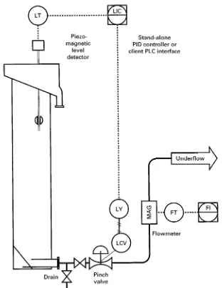
Figure 1 Example of level control loop. LT, level transmitter; LIC, level indicator and control; LY, level D/A signal conversion; LCV, level control device; MAG, magnetic flow detector; FT, flow transmitter; FI, flow indicator; PID, proportional-integral-derivative; PLC, programmable logic controller.
in feed Sow, Soatable material concentration or air rates. An example of this control is found inFigure 1. In water}oil separation, a periodic level rise may be organized to dump an accumulated organic pad. The simplest method of controlling level is to adjust the discharge height of the underSow using a ‘gooseneck’ or alternative form of gravity control. If this is not possible, then the level must be detected and that signal used to control either a variable-speed pump or control valve through a controller device. Detection devices includeSoats; pressure, capacitance, conduc-tance, and ultrasonic transducers, or combinations of these devices. The set point for the level is determined from the desired froth depth. Generally, the higher the level, the greater is the recovery of the Soating component and the lower its content in the overSow
(froth product). In more complicated systems, the level control may be used with froth or oil pad depth data to control overSow grade, withSow-monitoring devices for predictive control based on incoming feed, or multiple monitors to compensate for variations in air rate or feed composition.
Air
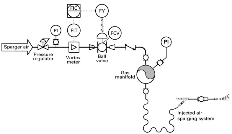
The purpose of the air loop is to control a volumetric
Figure 2 Example of air control loop. PI, pressure indicator; FIT, flow indicator and transmitter; FIC, flow indicator and controller; FY, flow D/A signal conversion; FCV, flow control device.
Air rate may be linked to predictive- or recovery-based systems.
Bias
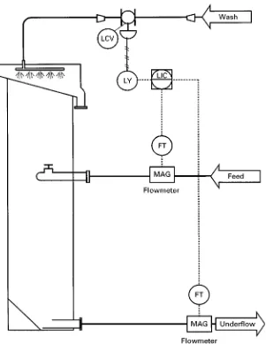
Bias is deRned as a downwardSow of liquid through the froth zone. Positive or downward bias is usually used when two suspended substances must be separ-ated from each other. If multiple separation stages are in operation, it is usually used on the last stage. The downwardSow of water through the froth is control-led by varying the water rate added to the froth zone. This Sow may be monitored by temperature, con-ductance or by Sow differences (water added to froth minus overSow water, or amount of liquid in underSow minus its amount in feed). The actual bias needed depends on the distribution of the water through the froth and the hydrophilic particle sizes.
Bias may be estimated using the difference in slurrySows (Figure 3) or, more accurately, by Rrst calculating the liquid volumetricSows usingSow and density meters.
Advanced Controls
It is possible } although not common } to control a column to separate according to a grade}recovery response curve. As grade increases or decreases in the feed, level, air rate and bias may be adjusted to achieve the most economical performance. This type of control requires a good predictive model based on theoretical knowledge, past experience and test work that uses information from upstream processes to
adjust column parameters in anticipation of changes (feed-forward control). Predictive systems provide feed-forward control and can incorporate either knowledge base or models (statistical or determinis-tic) into the control loop. Excessive complexity of models or control strategy does not improve the re-sults as the uncertainty in parameters grows. Such a system also requires extensive online detection equipment such as density,Sow and pressure meters. When these controls are implemented they are either model-based systems or some form of artiRcial intelli-gence (knowledge base, neural network systems based on fuzzy logic principles).
Operating Parameters
Process-operating variables are those inputs to the separator that may change with time and can be used to control the production quantity and quality. These include column control variables such as gas rate, washwater rate and froth or oil pad levels. There are also variables that may be controlled but are usually not even monitored, like bubble size distribution, and variables that depend on other parts of the operation such as volumetric feed rate, and feed solids charac-teristics: concentration, liberation and particle size distribution.
Gas (Air)
Figure 3 Example of differential feed}underflow bias control loop. LCV, level control device; LY, level D/A signal conversion; LIC, level indicator and control; FT, flow transmitter; MAG, magnetic flow detector.
with bubbles is dependent on the number of bubbles and their size distribution. The maximum particle surfaceSux removed depends on bubble surface area
Sux. As surface areaSux increases, so does the prob-ability of material}bubble aggregation (collection) within a speciRc range. This range is bounded by the increased mixing intensity as Sooding limits are ap-proached and the increase in bubble size that is usu-ally associated with an increase in gasSow. The total removal capacity, known as carrying capacity, can also be controlled by the gas rate since it is propor-tional to the speciRc bubble surface area. The carry-ing capacity is determined as the maximum amount of material which can be transported into froth in unit time from a unit cross-sectional area of a col-umn. It varies depending on particle size (for solid separation) and density of theSoating substance. The carrying capacity can be estimated from the balance
of the available bubble surface area and particle sur-faceSux. The normal range of superRcial air velocity is 1.0}2.5 cm s\1. In buoyant material separations, high gas rates may reduce the three-phase density of the aqueous suspension within the column to a den-sity lower than that of the product. This will cause an unstable pad that will sink if not quickly removed from the system.
Volumetric Feed Rate
The volumetric feed rate determines the vessel reten-tion time and strongly inSuences vessel mixing. An increase in superRcial suspension velocity results in lower gas limits as Sooding will occur at lower gas rates and increases the size of microbubbles which become entrained by downward Sow to the
the negative inSuence of mixing on grade and recov-ery (higher Peclet number) and lessen the retention time difference between Rne and coarse particles due to the settling. Typically, superRcial feed velocity is 0.5}1.3 cm s\1.
Feed Solids
An increase in the percentage of solids contained in the feed increases the residence time of those solids in the case of constant-column throughput of solids. The maximum solids load is determined by the vis-cosity of the system and may be only 0.25}2% (weight/weight) for paper de-inking applications to almost 70% for calcite/silica separation.
Washwater
Mineral separation columns can provide a positive bias which causes displacement of the feed liquid phase with washwater in the overSow. This substitu-tion virtually eliminates entrainedRnes from the
over-Sow product. Washwater distribution on to or into froth and itsSow rate should be individually tuned for each application depending on feed and concen-trate size distributions, froth stability, height and mobility, and on process objectives. Excessive wash-water supply causes froth disruptions, loss of recov-ery and dilution of products. Typically, superRcial washwater Sow rate does not exceed 0.15 cm s\1, although optimal rates depend on washwater distri-bution design and froth rheology. Washwater is not normally used in mineral roughing or scavenging operations, oil}water separations, or systems where entrainment is not a factor.
Froth Depth (Solid Separation)
The froth level maintained within the column is highly variable depending on the application. Some vessels may be operated with no froth, such as oil}water separators, or mineral columns operating on very large particles. In other cases, like molyb-deniteSotation, a froth as deep as 1.5 m may be run to ensure minimal entrainment and high selectivity. In general, a deep froth gives more opportunities for grade/recovery control and compensates for poor washwater distribution. Froth depth in mineral (solid}solid separation) column Sotation typically varies from 15 to 300 cm. The gas hold-up in froth gradually increases upwards due to froth sineresis and drainage along plateau canals. The entrainedRne particles return back to the lower (collection) section of the column by net downward liquid Sow in the froth (in the case of positive bias). Experimental data conRrm that, in some cases, upgrading of the product
occurs mainly in the froth zone, and not at the collec-tion stage.
It is important to note that an increase in froth depth decreases the volume of the remainder of the column which may be detrimental to overall perfor-mance.
Organic Pad (Liquid Separation)
In an oil separation vessel a hydrocarbon pad may be maintained at the top of the column. A deep pad minimizes water entrainment into the overSow but may increase the stripping of light hydrocarbons. When high air rates are used and the organics pad is not removed, droplets of organic phase may form and drop through the aerated zone of the column. Air rates must be lowered or the organics pad continu-ously removed as a froth to prevent sinking of the
Soated organics.
Bubble Size
Some types of spargers allow the change of bubble size distribution at nearly constant overall air rate. Both break-up and coalescence of bubbles occur after formation by the sparging devices which results in an equilibrium size distribution above a certain distance from the spargers. The average and deviation of this distribution depend on the surface tension at the air}water interface and turbulence in the cell. Gener-ally, smaller bubbles provide higher collection inten-sity and carrying capacity, but loaded microbubbles may sink or be entrained in the downward slurry. Also, maximum gas rate (at columnSooding point or transition to a churn-turbulent regime) is reduced with decreasing bubble size, meaning that there is a speciRc bubble size that gives the maximum upward rising surface areaSux. The point of columnSooding can be estimated (in the assumption of cross-section
Sow uniformity and narrow bubble size distribution) from the driftSux model. In many cases a combina-tion of smaller bubbles that provide the separacombina-tion and coarser transport bubbles that coalesce with the smaller bubbles results in optimalSotation rates.
Column Circuits
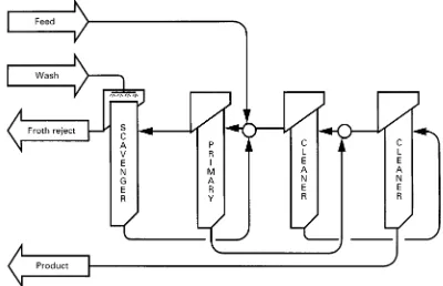
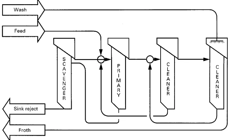
Figure 4 Hydrophilic product, solid}solid four-stage separation circuit. Example of iron ore. separation, iron ore puriRcation, coal cleaning,
sol-vent extraction and oil}water separation, paint recov-ery and newspaper de-inking. In addition, columns can be used to remove hydrophobic substances, or materials dissolvable in hydrophobic liquids, from water or soils. Examples are DDT, polycyclic aromatic hydrocarbons (PAHs) or other dangerous chemicals, oil production from tar sands, or the puriRcation or removal of algae or bacteria from cultures. All of these separations fall into three categories: solid}solid, solid}liquid and liquid}liquid separations.
Solid^Solid Separations
In order to get a good separation, the solids present must be liberated: that is, not physically or chemically attached, be suspended in a liquid medium and the
Sotation kinetics of the materials must be differ-ent. One or more stages of separation may be needed, depending on the kinetics and chemistry of the separ-ation. To achieve sharper separation when dif-ference in Sotation rate of components is not high and/or material is not completely liberated, compli-catedSowsheets including multiple recycle lines and regrinding are used. Regrinding operations for mid-dlings are used to avoid over-grinding of the bulk of material as it would cause reduction inSotation rate and selectivity for Rne particles. For Rnely dis-seminated ores, entrainment is a substantial factor
reducing sharpness of separation. Entrainment is a process of particle transfer to froth without their attachment on to bubble surfaces. This phenomenon can be explained by movement of small particles in the wake behind the rising bubble or within the static layer of liquid surrounding it. In machines with inten-sive mixing (impeller cells) the entrainment can also be caused by local upward slurrySows. TheseSows are not present in columns therefore reducing overall entrainment intensity and improving separation efRciency. A classical Sotation Sowsheet includes several cleaning stages generally linked by recycle of the cleaner tailings to previous stages. When more than one material isSoatable and separation depends only on degrees of hydrophobicity (molybdenite-chalcopyrite), four to six stages may be required. If insufRcient recovery is achieved in the primary vessel (rougher Sotation), scavenger cells may be used. In general, all stages do have a common separ-ation goal. For example, silica (impurity) is Soated away from hematite in a four stage iron ore circuit in
Figure 4. This circuit, or variations of it, is common when the valuable product is hydrophilic or an
under-Sow product of the column. The example gives four stages of separation; however, in many cases fewer stages are required.
The circuit for a hydrophobic product is shown in
Figure 5 Hydrophobic product, solid}solid four-stage separation circuit. Example of copper or plastics float.
Figure 6 Example of solid}solid separation: PAH from run-off water. Input of approximately 500 p.p.m. solids; filter feed of approximately 24%solids.
hydrophobic materials with similarSotation rates. As an example, this conRguration or variations of it can be used in phosphate, copper, zinc and plastics separ-ations, or for soil remediation.
Solid^Liquid Separations
In many circumstances a solid is present in a liquid stream that must be removed. Flotation is often a vi-able precursor stage, used to increase the percentage of solids, prior toRltration. This type of system can be used to Soat coal and associated PAHs from run-off water and upgrade the presentage of solids from p.p.m. levels up to 10}25%.Figure 6gives an example of such a circuit where PAHs from coking coal are Soated from a contaminated site run-off
water without removing the naturally occurring sand and silt.
Flotation can also be considered as an alternative to settling of naturally hydrophobic materials in wastewater treatment. This type of separation may also be used to remove bacteria or algae from water, or many solid substances from reaction vessels.
Liquid^Liquid Separations
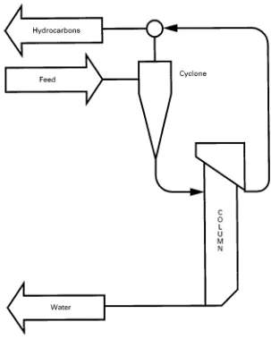
[image:8.568.89.468.562.684.2]Figure 7 Treatment of oil platform process water; generalized circuit.
production platforms prior to Rnal release of water, site run-off remediation and organics separation in hydrometallurgy. Columns are capable of remov-ing freelySoating hydrocarbons but usually not emul-siRed or dissolved hydrocarbons. In order to remove emulsiRed forms of hydrocarbons, a pre-aeration unit must be installed.
Oil production application Large amounts of water are involved in the extraction and production of oil. Column cells are used in the water treatment stage of production prior to release of the water back into the environment. In a typical circuit, as shown in
Figure 7, water from the process is Rrst passed through a cyclone or corrugated plate separator then to a column. The hydrocarbon concentrate from both of these vessels is returned for processing.
Site run-off remediation Sites that contain hydro-carbon contamination such as reRneries and
distribu-tion depots often have run-off waters that con-tain entrained hydrocarbons. These can be treated effectively with Sotation technology using a cir-cuit containing a column either working on its own or in conjunction with a settling tank. If emulsiRed hydrocarbons are present, a pre-aeration unit may be required on the column in order to achieve con-tamination level under 15 p.p.m.
Conclusion
Column Sotation has become the standard proven industrialSotation technique rather than an experi-mental method during the last decade. Nevertheless, its use in mineral-processing plants is mainly re-stricted at present to cleaning operations. The future ofSotation equipment development lies in the combi-nation of the advantages of impeller and column
Sotation and in the use of pneumatic machines in roughers.
As a greater share of Sotation operations are used for unconventional areas such as environmental applications (water treatment, soil remediation, etc.) and ultraRne and colloid particle separation, special machines will be developed combining
Sotation attachment at intensive aeration and mixing conditions and three-phase separation in a quiescent environment. This leads to the concept of pre-aer-ation in a reactor (a unit for attachment of recovering phase on to gas bubbles) and de-aeration in a separ-ator (a unit for separation of loaded bubbles from the bulk of three-phase suspension). Additional coarser bubbles can be added in a separator as a carrier to enhance the removal of loaded microbubbles by co-alescence.
This concept and other types of new combined
Sotation machines will provide for more
effec-tive and efRcient separation for a wide range of applications.
See also: I/Flotation. II/Flotation: Froth Processes and the Design of Column Flotation Cells.
Further Reading
Agar GE, Huls BJ and Hyma DB (eds) (1991)Column ’91. Proceedings of an International Conference on Column Flotation, June 2}6, 1991. Sudbury, Ontario, Canada: Canadian Institute of Mining and Metallurgy and Petro-leum.
Boutin P and Wheeler DA (1967) ColumnSotation devel-opment.Canadian Mining Journal88: 94.
Finch JA and Dobby GS (1990)Column Flotation. New York: Pergamon.
Gomez CO and Finch JA (eds) (1996)Column ’96. Proceed-ings of the International Symposium on Column Flotation, August 26}28, 1996. Montreal, Quebec, Canada: Cana-dian Institute of Mining and Metallurgy and Petroleum. Pal R and Masliyah J (1991) Process dynamics and control
of a pilot Sotation column. Canadian Metallurgical Quarterly30: 87}94.
Rubinstein JB (1995)Column Flotation,Processes,Designs and Practices. Basel, Switzerland: Gordon and Breach. Yingling JC (1993) Parameter and conRguration
optimiza-tion ofSotation circuits, part I: a review of prior work. International Journal of Mineral Processing38: 21}40.
Column Flotation Cells
See II / FLOTATION / Froth Processes and the Design of Column Flotation Cells
Cyclones for Oil/Water Separations
M. T. Thew, University of Bradford, Bradford, UK
Copyright^ 2000 Academic Press
Synopsis
Though the solid}liquid hydrocyclone has been estab-lished for most of the 20th century, satisfactory liquid}liquid separation performance did not arrive until the 1980s. The offshore oil industry had a need for compact, robust and reliable equipment for removingRnely divided contaminant oil from water. This need was satisRed by a signiRcantly
differ-ent type of hydrocyclone, which of course had no moving parts.
After explaining this need more fully and compar-ing it with solid}liquid cyclonic separation in mineral processing, the advantages that the hydrocyclone conferred over types of equipment installed earlier to meet the duty are given.