Using UML-B and U2B for formal refinement of digital
components
1Colin Snook Kim Sandström
University of Southampton, Nokia Research Centre,
Southampton, UK Helsinki, Finland
[email protected] [email protected]
Abstract
In this paper we look at using formal methods to verify the transformation of a digital design from abstract functional specification to bit level implementation. As both authors are in-experienced in formal proof we saw this as a test of the practicality of introducing proof tools in an industrial setting rather than an exemplar of such methods Rigorous verification is desirable in digital design because mistakes can be extremely costly. However, there are drawbacks and barriers to introducing formal notations. Formal notations are abstraction hungry, viscous and require insight, experience and look-ahead. Hence we specialise the UML to alleviate these problems by providing a semi-graphical form of the formal notation B based on existing visual modelling tools. With a small case study, we show the use of B-UML using an event style of modelling to refine a macro level function into a cascade of single bit cells. We attempt to prove the refinement with the assistance of available proof tools but find that the problem is deceptively difficult.
1 Introduction
In digital design, the problem is getting from a behavioural specification of a function or algorithm down to the RTL (Real Transfer Logic) implementation-level hardware description using a HDL (Hardware Definition Language) from which a netlist can be synthesised, without making any mistakes. Mistakes are extremely costly to rectify due to the production set-up and high volume output. The consequences of a product recall and the impact this can have on market perception are dire. Generally the behavioural specification of the hardware is quite detailed. Typically it will consist of a block diagram schematic of some kind that expresses the required functionality of the device precisely and in detail except for timing and synchronisation. However, there is still a long way to go before hardware can be implemented. For example, macro level functions may have to be implemented as a collection of single operations (as in our example) and even then the implied netlist connectivity must be chosen in such a way as to optimise the use of logic gates (for minimum silicon area, timing delay, and power consumption).
Using formal methods we can prove that there are no mistakes in these transformations. An event style of B is particularly suitable for some of these transformations because it expresses the event nature of hardware operation and allows us to model and control the refinement of high-level events into a sequence of more detailed ones.
The aim of digital design is to produce circuits for silicon chips. Digital design implements algorithms using highly integrated transistors on a small piece of silicon. Such transistors in turn implement basic elements called gates. Gates are quite simple logic units: AND, NAND, OR, NOR, XOR or INVERTER. The physical silicon technology used usually implements just a subset of these gates. There are silicon libraries for each physical silicon process that uses gates to implement actual
design elements. They implement slightly more advanced elements: such as Flip-Flops, Multiplexers, Adders, Shifters, etc. These elements are used to implement the design, which is then defined in a netlist. The netlist is automatically synthesised from a HDL, such as VHDL [2], which is usually written by the digital designer. If VHDL is used the refinement level of the code needs to be RTL to facilitate netlist synthesis.
1.1 Design
Methodology
In this study we use UML [10] and the U2B [11,12] tool to make an implementation that is suitable for netlist generation. As a design example we have chosen an adder. Although design libraries usually contain ready-made adders, some basic problems of hardware design are addressed in designing one. The adder is specified as an abstract specification and as a refinement in UML. The UML is translated into B notation [1] to facilitate formal proof of the design using the AtelierB prover [4]. The B could be used to generate VHDL from which a netlist could be synthesised.
1.2 Overview of U2B Translator
The U2B translator bears some similarities with other authors’ proposals (e.g. [8]) for translating UML into B. The main difference in our approach is that we specialise the UML in order to ensure that the resulting B is amenable to verification.
Structure and Static Properties. A B component is created for each class and includes modelling of class instances depending on class cardinality. Class cardinality may be fixed (set to a particular value), mutable (set to a range such as 0..n) or singleton (set to 1). If class cardinality is singleton, as in our example, the U2B translator creates a machine without any instance modelling. Since we use only singleton classes in our example the remainder of this description does not discuss instance modelling.
Attributes and (unidirectional) associations are translated into variables whose type is the attribute type (as defined in the Class diagram) or the associated class instances. Attribute types may be any valid B expression that defines a set.
In UML, model elements may have associated textual specification fields. For classes, one of these is a ‘documentation’ field. Any valid B clause can be added in the documentation field. For example, we use this method to specify invariants. Each clause must be headed by its B clause name.
Dynamic Behaviour. The dynamic behaviour is specified either in a text field or in a statechart attached to the class. An operation may be specified completely by (pre-condition and semantics) text fields, completely by statechart transitions, or by a simultaneous composition of both.
Textual Behaviour Specification. Text fields are used to specify pre-conditions, guards and semantics for the operation. UML does not impose a particular notation for these text fields. Since we wish to translate to B we use B notation.
Statechart Behavioural Specification. If a statechart model is attached to a class, U2B combines the behaviour it describes with any textual semantics of the operations. The name of the statechart model provides an attribute whose type is the set of states. Transitions associate operations with state changes. The transition’s event must be the operation name. Additional guards and actions may be attached to transitions. The translator finds all transitions associated with an operation and compiles a SELECT substitution of the following form:
SELECT statevar=sourcestate1 & sourcestate1_guards THEN statevar:=targetstate1 || targetstate1_actions WHEN statevar=sourcestate2 & sourcestate2_guards THEN statevar:=targetstate2 || targetstate2_actions ELSE skip END ||
1.3 The B Language and Toolkit
The B language is a formal specification notation that has strong decomposition mechanisms and good tool support. The primary aim of decomposition in B is to obtain compositionality of proof. B is designed to support formally verified development from specification through to implementation. To do this it provides tool support for generating and proving proof obligations at each refinement stage. To make large-scale development feasible, B provides structuring mechanisms to decompose a project into ‘modules’. Each module consists of ‘components’ (machines, refinements or implementations). Each module includes an abstract machine and possibly, refinements until an implementation is reached. The implementation may then import abstract machines of other modules in a hierarchical module structure.
Event B. In our example, we use an event style of B where operations represent events that occur in the system. In conventional B, operations represent the response of a system to some external stimulus. In event B [7], operations are replaced by events and represent something that occurs spontaneously (subject to a guarding predicate) within a closed system. Some events model interfaces and can be viewed as the occurrence of both the stimulant and the reaction. Further intermediate events may be added, or existing events may be split or merged, as refinements add more detail to the model. There is no prover for event B at this time. Instead a translator [5] converts event B into conventional B so that the AtelierB tool can be used.
2 Adder Case Study
Because of the causal nature of a cascading structure event B was chosen to describe an abstract specification and a refinement of the design.
The abstract design is attributed one event for data input and one event for data output. At closer inspection it turns out that these two events correspond to the active and the passive edge of the clock pulse. Data inputs are read at the active edge of clock and outputs are ready at the passive edge of the clock. Events that occur in between are defined in the refinement
In the refinement an event is defined for every physical step of the calculus process. Data acquisition and calculus for every cell is added separately. The final definition is very close to actual physical events on the silicon chip.
Adder general structure. In a digital design with arithmetic operations, numerical values are implemented as bits. A bit vector represents a value. It's actual semantic is determined by the designer. A bit vector might be an integer or it might be a fixed or floating-point number. For simplicity we chose to implement an integer adder of fixed width. In the case of our adder the semantics of a bit vector is an integer. For the example, we defined the bit width of the inputs and outputs to be four. In addition an input carry and an output carry were added as a control structure for overflow exceptions.
The abstract adder can be seen as a black box with two inputs and one output and a known relationship between inputs and outputs. Such an abstraction is suitable for any digital module of any size. Thus, the adder can within this study represent the abstraction of much more complex structures and we get a hint of typical design problems using formal proof. In no way do we imply that a bigger more complex design would be equally ‘easy’ to prove using formal methods, but some conclusions may be drawn.
2.1 The Adder as a Generic Component
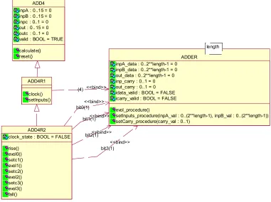
Initially we defined a generic addition component with parameterised bit vector length. The aim was to extract the common addition function that exists once as a four bit addition in the abstract specification and four times as single bit additions in the refinement. This resulted in the class structure shown in Fig.1. However, although the generic adder component allows some reuse of proof between abstraction and refinement its proof is very easy and mostly automatic. On the other hand, the generic adder component was found to make the refinement proof much more complicated especially as many of the operators used in the genericity were not supported by rules in the prover rule base. We could not achieve a proof with this structure.
On the one hand, the difficulty of proof (as well as other re-use motivations) makes the identification of generic functions desirable in order to promote the re-use of proven specifications. On the other hand the difficulty of proof requires that we keep the specifications as simple as possible and this prevents the addition of features needed to provide genericity. We see this as a major obstacle in the adoption of B throughout industry. Work to tackle this problem is underway [13].
length
ADDER inpA_data : 0..2**length-1 = 0 inpB_data : 0..2**length-1 = 0 out_data : 0..2**length-1 = 0 inp_carry : 0..1 = 0 out_carry : 0..1 = 0 idata_valid : BOOL = FALSE icarry_valid : BOOL = FALSE
evol_procedure()
setInputs_procedure(inpA_val : 0..(2**length-1), inpB_val : 0..(2**length-1)) setCarry_procedure(carry_val : 0..1)
ADD4R2
clock_state : BOOL = FALSE
rise() evol0() setc1() evol1() setc2() evol2() setc3() evol3() fall()
ADD4R1
clock() setInputs()
ADD4 inpA : 0..15 = 0 inpB : 0..15 = 0 inpc : 0..1 = 0 out : 0..15 = 0 outc : 0..1 = 0 valid : BOOL = TRUE
calculate() reset()
(4) <<bind>>
bit0(1) <<bind>>
bit1(1)<<bind>>
bit2(1)<<bind>>
[image:4.595.114.495.300.584.2]bit3(1) <<bind>>
Fig. 1 - Attempt to use generic parameterised addition component
2.2 Abstract
Specification
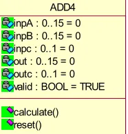
The abstract specification is a singular class, ADD4, (Fig. 2) that has attributes representing the inputs and outs of the addition and two operations representing the setting of new input data and the availability of the output. A boolean attribute, valid, indicates when the output is ready. A class invariant is defined that the events must obey. This defines that when valid is true the outputs must equal the addition of the inputs.
specification there is little to prove. Five proof obligations were generated. The automatic prover proved three of these and the remaining two were proved interactively using the predicate prover.
ADD4 inpA : 0..15 = 0 inpB : 0..15 = 0 inpc : 0..1 = 0 out : 0..15 = 0 outc : 0..1 = 0 valid : BOOL = TRUE
[image:5.595.259.352.105.202.2]calculate() reset()
Fig. 2 - Class representing abstract Specification
INVARIANT (valid=TRUE => outc*16+out=inpA+inpB+inpc) calculate
Precondition: valid=FALSE
Semantics: out:=(inpA+inpB+inpc) mod 16 || outc:=(inpA+inpB+inpc) / 16 || valid:=TRUE
reset
Precondition: valid=TRUE
Semantics: valid:=FALSE ||
ANY ia,ib,ic WHERE ia: 0..15 & ib:0..15 &ic:0..1 THEN inpA:=ia || inpB:=ib || inpc:=ic
END
2.3 Refinement
The refinement of the adder is a cascading structure. Calculation happens in order of the bit cardinality, where the LSB is calculated first and the MSB last. Calculation of a value is triggered by a clock pulse. At the active edge of clock, valid inputs are made available. At the passive edge of the clock the calculation is ready. Each cell in the cascading structure represents one bit in the adder’s output. The inputs of a cell are two one-bit inputs and an input carry. Outputs are the result plus carry. The output carry of each bit addition becomes the input carry of the next higher bit addition. This is why the bit additions have to be cascaded into sequence. The output carry from the MSB addition is the output carry of the overall vector addition.
The adder has the following behaviour:
data = (inputA + InputB + input_carry) mod maxint carry = 1 iff (inputA + InputB + input_carry) > maxint where, maxint = 2**bitwidth
The full adder would be composed of the cells as follows
A3 B3 A2 B2 A1 B1 A0 B0 Ci + + + + + + + + | ---- ---- ---- ---- | C3--| |-C2-| |-C1-| |-C0-| |---| | ---- ---- ---- ---- | + + + + Co O3 O2 O1 O0
Where Ax and Bx are data input vectors, Ox is the output vector, Ci is carry in and Co carry out, Cx are the internal cell carry bits
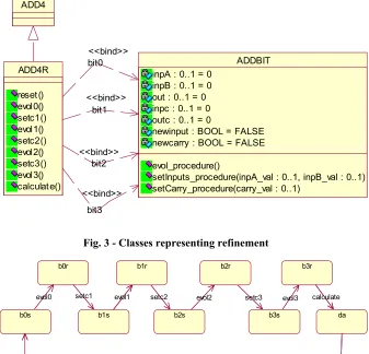
associated with the addition of an individual bit is represented in a separate class ADDBIT. This class acts as a template class and is instantiated four times by ADD4R to represent the four bit additions. ADDBIT has attributes to represent its inputs and outputs and to indicate when the output is available. It has operations to set its data bit inputs (inpA and inpB), set its carry bit input (inpc) and calculate an answer (out and outc). The four instantiations of ADDBIT::inpA together form a data refinement of the bit vector attribute inpA of ADD4. Similarly for inpB and out. The bit0.inpc attribute of the instantiation representing bit0 corresponds to inpc of ADD4. Similarly, bit3.outc corresponds to outc of ADD4. The other carry bit instantiations are new data of the refinement.
ADD4
ADD4R
reset() evol0() setc1() evol1() setc2() evol2() setc3() evol3() calculate()
ADDBIT inpA : 0..1 = 0
inpB : 0..1 = 0 out : 0..1 = 0 inpc : 0..1 = 0 outc : 0..1 = 0
newinput : BOOL = FALSE newcarry : BOOL = FALSE
evol_procedure()
setInputs_procedure(inpA_val : 0..1, inpB_val : 0..1) setCarry_procedure(carry_val : 0..1)
bit0 <<bind>>
bit1 <<bind>>
bit2 <<bind>>
[image:6.595.137.474.191.515.2]bit3 <<bind>>
Fig. 3 - Classes representing refinement
da b0r
b0s evol0
b1r
b1s
setc1 evol1
b2s setc2
b2r
evol2
b3s setc3
b3r
evol3 calculate
reset
Fig. 4 - State chart defining sequence of events
The following gluing invariant was specified initially for ADD4R:-
clock_state : CLOCK_STATE & /*glueing invariant */ valid= bool(clock_state=da) &
inpc=bit0.inpc &
inpA mod 2 =bit0.inpA & (inpA/2) mod 2 =bit1.inpA & (inpA/4) mod 2 =bit2.inpA & (inpA/8) mod 2 =bit3.inpA & inpB mod 2 =bit0.inpB & (inpB/2) mod 2 =bit1.inpB & (inpB/4) mod 2 =bit2.inpB & (inpB/8) mod 2 =bit3.inpB &
[image:6.595.75.520.578.760.2]( clock_state=da => outc=bit3.outc ) &
Verification. The verification of ADDBIT is straightforward as it is purely a specification. Four proof obligations were generated. The automatic prover proved three of these and the remaining one was proved interactively using the predicate prover.
The verification of ADD4R involved the main verification effort. The verification requires us to prove that if the bit additions are fed with the relevant bits from the integer addition then the sequence of cascaded bit additions will produce a set of bits which can be composed to equal the result of the integer addition. The difficulty comes from the cascading of carry bits. For the final answer it is necessary to unravel the production of the carry bits from each bit addition until the answer depends only on the original input bits. During this process it was found necessary to add to the invariant to describe the establishment of the intermediate results from the bit additions. The necessary additions to the invariant seemed obvious from the proof obligations. For example:
/* bit 1 */
(clock_state: {b1s,b1r,b2s,b2r,b3s,b3r} => bit1.inpc=bit0.outc) & (clock_state: {b1r,b2s,b2r,b3s,b3r} =>
bit1.out= ((bit1.inpA + bit1.inpB + bit0.outc) mod 2)) & (clock_state: {b1r,b2s,b2r,b3s,b3r} =>
bit1.outc= ((bit1.inpA + bit1.inpB + bit0.outc)/2)) &
Atelier B generated 127 proof obligations of which the automatic prover proved 101. A further 24 were proved interactively leaving 2 unproved. For the 24 PO’s that were proved interactively the proofs were easy to envisage but very tedious to perform. This is largely due to the poor interface to the interactive prover. An improved interface providing easier selection of hypotheses and specification of commands is currently being worked on and this should assist greatly in dispensing with these fairly trivial PO’s. Many of the proofs were very similar in the sequence of commands, differing only in, for example, the particular hypothesis added. More generic commands (e.g. that use pattern matching to select a particular hypothesis) would have enabled greater re-use of proof commands.
The 2 unproved PO’s are to establish the gluing invariant of the main result for the output, out, and the output carry, outc.
"`Local hypotheses'" & clock_state$1 = b3r &
`Check that the invariant (clock_state = da => out = bit0out+2*bit1out+4*bit2out+8*bit3out) is preserved by the operation - ref 4.4, 5.5'"
=> (inpA+inpB+inpc) mod 16 = bit0out$1+2*bit1out$1+4*bit2out$1+8*bit3out$1
"`Local hypotheses'" & clock_state$1 = b3r &
"`Check that the invariant (clock_state = da => outc = bit3outc) is preserved by the operation - ref 4.4, 5.5'"
=> (inpA+inpB+inpc)/16 = bit3outc$1
These expressions can (rather tediously!) be unravelled along the chain of carry bits to obtain an expression in terms of only the original inputs (inpA, inpB and inpc). We can easily see from our knowledge of arithmetic addition of bits that the expressions are equivalent. However, we think it is not possible to get the prover to prove it without explicitly adding the same rule to the prover rule base. It turns out that the transition from integers to vectors of bits is too big a refinement step to prove.
more helpful invariant that was inductive for each (bit) step of the calculation and hence true at the final step. To some extent we were put off from attempting this more desirable generic approach by the lack of rules in the prover rule base for the necessary mathematical operators such as division, modulus and exponentials. Along with the poor user interface this made us favour making the problem as simple as possible.
2.4 Implementation
Our refinement showed the equivalence of the operation at a bit vector level with a sequence of bit operations. However the refinement still defines the bit operations at a functional level. This is necessary to ensure that the verification is manageable. However, this makes the refinement unsuitable to be used as an implementation (i.e. for netlist synthesis). A further stage of refinement is needed to arrive at a specification in a form that is optimised with respect to its silicon footprint and that can be converted into VHDL code.
Below is the specification of a cell, where the output value, Out, and output carry, OutC, are expressed as a function of input bits, inA and inB, and input carry, C.
Out/OutC || inB
--- inA || 0 | 1 ============================ 0 || C/0 | ~C/C --- 1 || ~C/C | C/1
Thus if, '*' is bitwise 'AND' and '(+)' bitwise 'XOR' we have Out = (inA(+)inB) (+) C
OutC = (inA * inB) (+) ((inA(+)inB) * C)
An implementation could be made using two 'AND' gates and two 'XOR' gates for 'OutC' and two 'XOR' gates for 'Out'. One 'XOR' gate can be used by both Out and OutC. This adds up to a total two 'AND' gates and three 'XOR' gates. Our proven implementation would have to match this optimal implementation.
3 Conclusions
A similar case study of addition was presented by Cansell and Mery at FDL’02 [3]. Since we wished to test our ability as novices and typical engineers (who had been given three weeks standard training by ClearSy) to create and prove formal models, we did not look at this work until after we had made our own attempt. Their approach seems to involve some clever tricks and doesn’t appear obvious or natural to an engineer. We suspect that, for formal methods to be popular in industry, they must work with a straightforward and obvious style of modelling. However, from our experience on this example, we agree wholeheartedly with their statement “We think that the use of provers should be improved by providing better interfaces and better structuring mechanisms to make them more attractive”.
we were led away from this approach because the prover lacks rules for the operators needed in bit manipulation and therefore we attempted to minimise their use.
From the proofs we managed to achieve our impression was that the process is more difficult than it should be. This is mainly due to limitations of the current version of tools for performing the proofs. For many proofs a strategy was fairly easy to envisage but very tedious to perform and to a significant degree this was due to the lack of user friendliness in the interface of the interactive prover. Many proofs were very similar and it would be useful to have a means to ‘program’ the prover to enable the ‘try everywhere’ facility to be used more effectively or for sequences of proof commands to be used at stages within a proof. A further or consequent problem was that any attempt to obtain generic components makes the proof obligations significantly more difficult to prove. With the current tools we think it unlikely that formal proof would be practical for use in industry for verifying the design of electronic components but we envisage improvements that may one day make this possible.
Due to the dualistic semantic of integer and bit, the refinement contains some B expressions that are valid for both the integer based abstract specification and the bit based refinement. The expressions are
validOutput(od_,oc_)==
od_ = (inputA.data + inputB.data + inp_carry) mod(2**sz) & oc_ = (inputA.data + inputB.data + inp_carry) / 2**sz
(where sz, the number of bits, is 4 in the abstract specification and 1 in the refinement).
We wished to base our specification and refinement upon a generic definition independent of vector length (i.e. a bit is a vector of length one). However, due to the lack of prover rules we found that the operators necessary to introduce this genericity (e.g. 2**sz) made the proof significantly more difficult.
Although, this example doesn’t make extensive use of UML features, the B-UML specification still provides a useful visualisation of the structure and of the state variable. It was particularly useful in discussing and trying different structures.
4 Further
work
We will attempt alternative strategies to the refinement and its invariant in an attempt to discover guidance in how to tackle such problems. Further still, we envisage a second refinement to obtain the final implementation in terms of implementable gates.
5 Acknowledgements
Michael Butler (University of Southampton) provided re-assurance that the final 2 proofs were difficult and suggested that a more generic approach may well be easier to prove. Thierry Lecomte and Laurent Voisin of ClearSy answered questions about using AtelierB.
6 References
1. Abrial, J.R.: The B Book - Assigning programs to meanings. Cambridge University Press. (1996) 2 Ashenden, P.J.: The designers guide to VHDL, ISBN 1-55860-270-4
3. Cansell, D. & Méry, D.: Integration of the proof process in the system development through refinement steps. 5th Forum on Specification & Design Language - Workshop SFP in FDL'02. (Marseille, France). 2002. 12 p.
4. ClearSy: AtelierB User Manual, V3. ClearSy System Engineering, Aix-en-Provence (F). 5. ClearSy: Event B Reference Manual, V1. ClearSy, (2001).
7. LeComte, T.: Abstract System Modelling. Draft http://www.keesda.com/pussee/ (2003)
8. Meyer, E. & Souquières, J.: A systematic approach to transform OMT diagrams to a B specification. In J. Wing, J. Woodcock, J.Davies, editors, World Congress on Formal Methods in the Development of Computing Systems, FM’99, Vol. I, LNCS 1708, Springer-Verlag, pp.875-895. (1999)
9. PUSSEE project web site: http://www.keesda.com/pussee/
10. Rumbaugh, J., Jacobson, I. & Booch, G.: The Unified Modelling Language Reference Manual. Addison-Wesley. (1998)
11. Snook, C. and Butler, M.: Using a graphical design tool for formal specification. In G.Kadoda, editor, Proceedings of the 13th Annual Workshop of the Psychology of Programming Interest Group, pp. 311-321. (2001)
12. Snook, C. and Butler, M.: U2B - UML to B translation tool and Manual V4.4 available at http://www.ecs.soton.ac.uk/~cfs/U2Bdownloads/U2Bdownloads.htm