RECOMP III
GENERAL PURPOSE DIGITAL COMPUTER
PROGRAMMING MANUAL
First Printing - August, 1961 Rei s sued - April, 1963
CONTENTS
Page
1. INTRODUCTION 1
II. BASIC COMPUTER DESCRIPTION 2
Memory 2
Main Memory 3
High -Speed Memory 3
Control Console 3
Switche s 4
Registers 4
A-Register 5
R-Register 5
B-Register 5
C -Register 5
G-Register 5
Index Re gi ste r
6
Optional Floating Point Hardware
6
III. INPUT / OUTPUT 7
Flexowri te r 7
Facitape 7
Facitape High-Speed Tape Reader 10 Facitape High-Speed Tape Punch 10
Other Input/Output 10
IV. PROGRAMMING 11
Command Structure 11
Data Structure 11
Data Word 12
Command Format 13
List of Commands 13
Use of Index Register 22
Programming Example s 22
Floating Point 24
Floating Point Commands 25
V.
PROGRAMMING SYSTEMS 26RECOMP III Interpretive Program 26
RECOMP III Compiler 27
APPENDIX I - Li st of Commands 28
APPENDIX II - Character Code s 30
-CONTENTS - Continued
ILLUSTRATIONS: Figure l.
Figure 2. Figure 3. Figure 4. Figure 5.
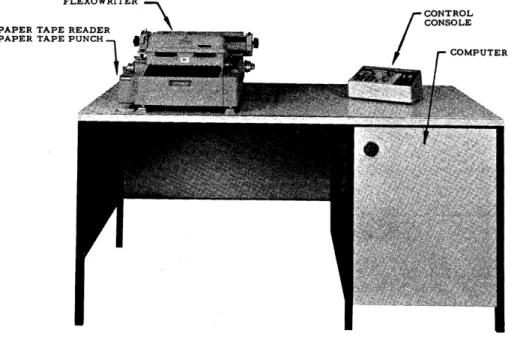
RECOMP III Computer Components
---Control Console---Flexowri te r
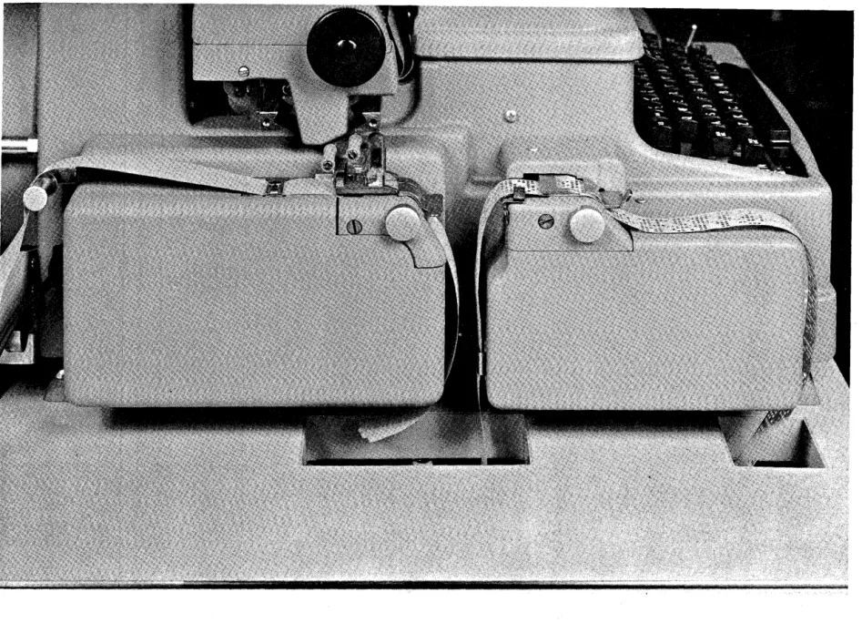
---Flexowriter Tape Punch and Tape Reader
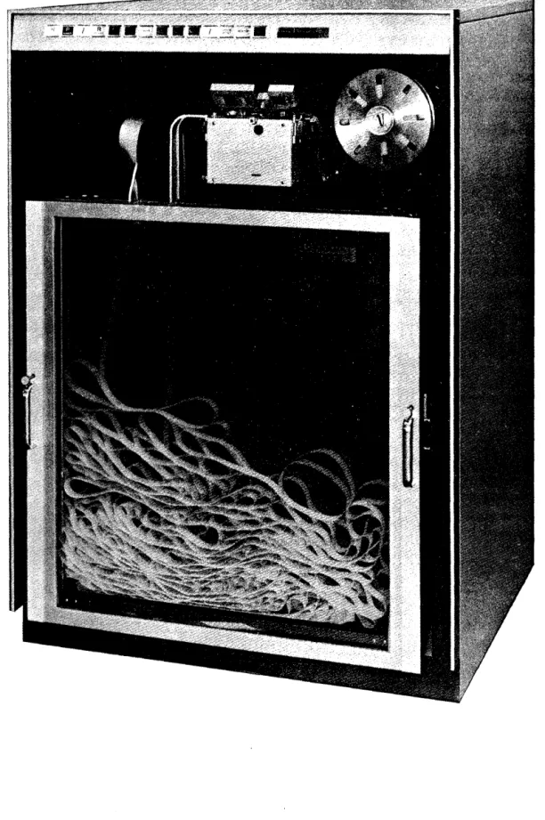
----FACITAPE Console---2 3 7 8
1. INTRODUCTION
RECOMP III is a solid-state, general purpose, digital computer de signed for scientific and industrial use. It has a 4096 - word memory with a 40-bit word length. Each word contains two pro-gram instructions, therefore, the memory can hold a propro-gram with over 8000 instructions. RECOMP III offers a large command list of 49 commands, or, when optional floating point hardware is used, 53 commands. Its Index Register makes machine language programming a simple task for any engineer or technical person. RECOMP III will accommodate up to four inputs and four outputs, and will handle 5 through 8 channel tape. Its equipment is easily accessible for servicing, and printed circuitry reduces mainten-ance to a minimum. The computer operates from any standard outlet.
II. BASIC COMPUTER DESCRIPTION
The basic computer (Figure 1) consists of three assemblies: memory, Flexowriter, and control console, The operator is concerned only with the Flexowriter and control console.
MEMORY
The mem.ory is a magnetic disk containing basic timing channels, arithmetic registers, rapid access loops, and area for information
storage. It will hold 4096 40-bit words, with two instructions per word, or a total of 8192 internally stored instructions - - a capacity comparable to that of many large -scale computing system.s.
In operation, the memory rotates at 3450 rpm. The disk is coated with ferrous oxide similar to that on conventional magnetic record-ing tape. As the disk rotates past each stationary recordrecord-ing (write) head, a magnetic signal is recorded into the oxide coating, and remains until replaced by new information. To extract information from the di sk, a reproducing (read) head similar to the recording head is used. Extraction of information from the memory doe s not change its contents.
FLEXOWRITER
PAPER TAPE READER PAPER TAPE PUNCH
1
Figure 1. RECOMP III Computer Components
-The disk memory is divided into two portions: the main memory and the high-speed memory.
Main-Memory
The main memory holds 4080 40-bit words. It is nonvolatile, pro-tecting stored data from erasure unless erasure is desired. In-formation in the main memory will not be destroyed during power interruption or power -off condition.
Words in the main memory are addressed by four octal digits from 0000 to 7757. Average access time is 9.3 milliseconds.
The sector tract, an inaccessible portion of the main memory, contains permanently recorded bootstrap and diagnostic routines. These built-in programs facilitate program loading and easy, fast computer checkout.
High-Speed Memory
Rapid access to stored information is provided by two high-speed recirculating loops, L and V, of eight words each. Available in programming, the L and V loop addre sse s are indicated by octal 7760 to 7767, and by 7770 to 7777, respectively. One to eight words can be transferred by option to the L and V loops, and by option from the L loop. Information contained in the loops is volatile.
Average access time to the high-speed memory is 1. 8 milliseconds.
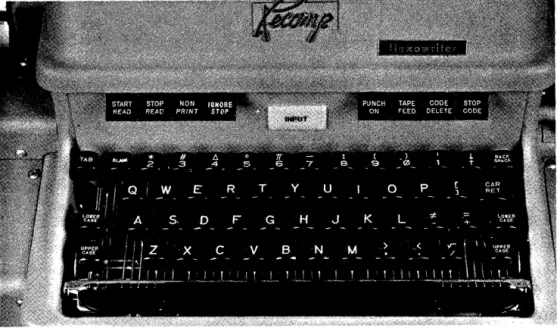
CONTROL CONSOLE
The control console provide s fast, simple communication between the operator and computer equipment. (See Figure 2.) Its few
Switches on the console are: POWER ON-OFF, COMPUTE, INPUT SELECT, OUTPUT SELECT, and LOCATION RESET. Indicator lights on the console are: ON, READY, COMPUTE, OVERFLOW, and 13 location indicators.
The ON light appears when the power switch is turned ON. The READY light appear s approxim.ately 45 seconds after the power is turned on. At this time, the com.puter is ready for operation. The COMPUTE switch has 3 positions: CONTINUOUS, to start the com.puter in continuous operation under program. control; HALT, to stop cOITlputation; and SINGLE COMMAND, to execute one com.m.and at a tiITle.
The COM.PUTE light is on during all com.putations.
The OVERFLOW light appears when an overflow condition is detected. It does not halt com.putation. The OVERFLOW light ITlust be turned off by prograITl control.
The 13 location indicator lights di splay the octal location of the next instruction to be executed.
The LOCATION RESET switch sets the location counter to 0000.0; i. e., when com.putation is started, the next instruction will be taken from. 0000. O.
The INPUT SELECT switch provides a m.eans for operator select-ion of one of four input device s. When thi s switch is placed on "autom.atic", the program. has control of the input. The operator m.ay override program.m.ed input control by selecting som.e alternate device, such as the Flexowriter keyboard or tape reader, a FACI-TAPE reader, or a card reader, etc.
The OUTPUT SELECT switch provides a means for operator selection of one of four output devices. When this switch is placed on "autom.atic", the program. has control of the output. The operator m.ay override program.m.ed output control by select-~ng SOITle alternate device, such as the Flexowriter typewriter, or tape punch, a FACITAPE punch, or a card punch, etc.
REGISTERS
In addition to the m.ain ITlem.ory and the high - speed m.eITlory, the RECOMP III cOITlputer unit includes five recirculating registers: A-register, R-register, G-register, B-register, and the C-regi ster. In conjunction with 'appropriate swi.tching and control
-elements, these registers are devices for retaining information and carrying out basic arithmetic and logical operations.
The five registers each contain one word. The action and pro-ce s sing of information within them controls and propro-ce s se saIl data. Contents of the various recirculating registers are not retained when power to the computer is off.
A-Regi ster:
The most important regi ster is the A (or Accumulator) regi ster, used in all arithmetic operations. Thi s regi ster holds .the re suits of arithmetic and logical operations and input/ output instructions. R-Register:
The R-regi ster, often termed the lower accumulator or remainder register, acts as temporary storage for the remainder in a division, or for the least significant half of a product obtained in multiplication. It may be considered in this wayan extension of the A-register. It is also used to extend the range of the divident in the DIVIDE
command, and permits the accumulation of a double length product resulting from the MU.LTIPLY command.
B -Register:
The B-register, often referred to as the number register, is an intermediate storage register which is not directly addressable by the programmer. It holds the number or operand whose address is found in the command.
C-Register:
This is the command register from which all instructions are executed. Addres s modification directly affects the operand add-ress of the current instruction under execution within the C or command register.
G-Register:
INDEX REGISTER
One of the major advantages of the RECOMP III over other low-cost computers is its built-in index register. This register, under programmed control, modifies addresses and controls the number of time s a given set of instructions will be executed. It allows a set of instructions to be repeated at very high speeds, using new data each time. Thi s regi ster can cut programming time by 35 to 50 per cent, thus substantially lowering operating costs.
OPTIONAL FLOATING POINT HARDWARE
One of the most tedious tasks encountered by a programmer is the problem of scaling. Scaling problems can be reduced
sub-stantially by the use of floating point. Two approaches are avail-able for obtaining floating point capabilitie s in RE COMP III: (l) Floating point logic can be simulated by the use of programs designed for this purpose. Because of the machine time and space required for this technique, it is considered to have limited use. (2) The RECOMP III optional floating point hardware can be, and should be, obtained when the application of floating point programs is to be at all extensive.
-III. INPUT - OUTPUT
A Flexowriter is used for input/ output operations with the basic RECOMP III computing unit. (See Figure 3.) For increased input/ output capacity, a FACITAPE reader/punch console may be attached to the comput~r as an optional device.
FLEXOWRITER
Information can be entered into, the computer either by typing in commands and data on the Flexowriter keyboard, or by entering through the reader commands and data which were prepared pre-viously on punched paper tape. (See Figures 3 and 4.) Results can be either typed out or punched. The speed of input and output is 10 characters per second.
FACITAPE
The FACITAPE console, housed in a handsome cabinet, offers input/ output facilities which are considerably faster than the
standard Flexowriter on RECOMP III. (See Figure 5.) Whenever special data handling is requi red, the use of F ACIT APE punch and reader acce s sorie sis recommended.
FACITAPE High-Speed Tape Reader
This high-speed tape reader has a read ra,te of 600 characters per
second. Its positive braking method stops tape
within a character.
It is a capacitance reader light.
The
FACITAI~reader will handle any color and all types of paper tape.
It is inserted or removed simply by lifting the hinged cover.
FACITAPE Hign - Speed Tape Punch
This high-speed heavy-duty punch can operate at the rate of 1.50 characters
per second.
OTHER INPUT/OUTPUT
Up to four input and output devices can be attached to the
HE.:COMPIII
computer, including plotters, A-D converters, D-A converters and other
devices.
-I V. PROGRAMMING
COMMAND STRUCTURE
The computer executes commands sequentially unless a transfer command is encountered. There are two commands per word as shown below.
' - - - ADDRESS _ _ - . . J
... - - - FIRST COMMAND - - - - -... . ; 1
-In general, a command pair (word) is copied into the command C-register; the left command is executed; then the right command is executed; and then the next command pair is copied into the command C-register, etc. (The Location Counter is increased by one -half word for each command. )
The sign of a left -half command is the actual sign of the word. Thi s sign is ignored by the computer. The effective sign of a right-half command is the 20th bit. (See diagram above.) If the sign of a right-half command is minus (a 0 bit), the contents of the Index Register will be subtracted from the address portion of the command as the command pair is being copied into the
command register.
The
6
bits of the operation tell the computer what to do, and the channel and sector portions of the command tell the computer where to get the data or operand. The half-word bit tells the com-puter which half-word to refer to (0 for left-half---l for right-half) in transfer commands and a few others. The half-word bit is ignored in most commands.DATA STRUCTURE
DATA WORD
The binary point (analogous to decimal point) may be 'thought of as lying between the sign and first bit (b
=
0) such that all numbers are fractions Ie s s than 1; or it may be thought of a's lying after the 39th bit, such that all numbers are integers; or (preferably) as lying in the position which would give the number its true (unsealed) value (analogous to a desk calculator).(The programmer usually keeps track of the binary points of hi s data and results in the "remarks" column of his coding sheet. ) . If the binary point is numbered from 0 (left end of word) to 39
(right end of word), some simple rules suffice to determine the binary point of the result of arithmetic operations. (Note that binary points less than 0 and greater than 39 are permissible. ) A small number such as .0000010110 would "-fit" at b
=
-5 since it has no integral part and has 5 leading zeros in the fractional part. (The absolute value of a number at a binary point of b is less than 2b. )These rules are as follows:
(1) In addition and subtraction, the binary points of the two operands must be the same. Shift commands are pro-vided to allow the binary points to be lined up.
(2) In multiplication, the binary point of the product is equal to the sum of the binary points of the two operands; e. g. , A b = 20 x B b = 10 = AB b = 30; A b = -5 x B b = 50 = AB b
=
45 (six bits to the right of the "A" regi ster in the"R"
register).(3) In division, the binary point of the quotient is equal to the binary point of the dividend minus the binary point of the divisor; e. g., A b
=
30 / B b = A b=
20.B
The binary point of the remainder (in the
"R"
register) is equal to the binary point of the dividend minus 39 (or to the original binary point of the dividend counted from the left end of the"A"
register).
-COMMAND FORMAT
Commands are usually written in a form which uses octal (three bits at a time) for the operation and address and binary for the half-word bit. For example: +7312340+7243210 means,
ADD the word in channel 12 word 34 (half-word bit zero) SUB the word in channel 43 word 21 (half -word bit zero) A program exists which will accept thi s form of coding and convert it to binary for storage in memory.
(R3P-l,
seeAppendix IV)
LIST OF COMMANDS
The operation codes usually consist of two octal digits each. However, some operation codes must have a one in the highest, next to highest, or half-word bit, of the address. These will be listed as XX. 4, XX.2, or XX. 1, respectively.
Registers not mentioned are not affected. No source is ever affected (non-de structi ve readout). The half -word bit is ignored unless mentioned. The A, R, and Index Registers will be referred to as A, R, and I.
Mnemonic Octal
CLA 37
36
RCA 77
RCS
76
ADD 73
De scription
Clear and add. Replace the contents of A with the contents of the word addre s sed. Clear and subtract. Replace the contents of A with the negative of the contents of the word addre s sed.
Replace the contents of R with the contents of A. Then replace the contents of A with the contents of the word addre s sed.
Replace the contents of R with the contents of A. Then replace the contents of A with the negative of the contents of the word addressed.
Add arithmetically the contents of the word addressed to the contents of A and put the
Mnemonic Octal De scription SUB MPY DIV ALS NOTE: ASC ASV 72
63
66
02Subtract arithmetically the contents of the word addressed from the contents of A and put the difference in A .. If over-flow occurs, the overover-flow indicator will be turned ON, and the sign of A will be reversed.
Multiply the contents of A by the contents of the word addressed, and replace the contents of A and R with the product. Both A and R will have the sign of the product.
Divide the contents of A and R (dividend has sign· of A) by the contents of the word addre s sed and replace the contents of A by the quotient and the content s of R by the remainder (with original sign of A). If overflow occurs, the overflow indicator will be turned ON.
Shift the content s of A left the number of places in the least significant bit of the channel portion and the 6 bits of the sector portion of the address (0 to 127 decimal). Bits leaving the left end of A are lost. Bits entering the right end of A will be zeros. The sign position of A is neither shifted nor affected.
All shift commands utilize the same seven bits to indicate
-
the amount of shift, either 12-18 for a left-half command or 32 ~38 for a right-half command.02.4
02.2
Shift the contents of A left the aITlount of shift specified or until A is normalized (the left-ITlost bit of A is a one), whichever occurs first. Decrement I by the number of places actually shifted.
Shift the contents of A left the amount of shift specified. Turn the overflow indica-tor on if any of the bits lost from the left end of A was a one.
-NOTE that the command 02.
6,
which has one s in both of the two high positions of the address, acts as an 02.4 command since no overflow can occur.Mnemonic Octal
ARS 03
XAR 56
EXT 70
TRA 51
TPL 55
TMI 53
TOV 52
HTR 71
Description
Shift the contents of A right the amount of shift specified. Bits leaving the right end of A are lost. Bits entering the left end of A will be zeros.
Exchange the contents of A with the contents of R.
Extract (bitwi se logical and). Compare the contents of A with the contents of the word addressed bit by bit, including the
sign position. Whenever the correspond-ing bits of A and the word addressed are both l' s, leave the 1 in
A.
Whenever either of the corresponding bits of A and the word addressed is a zero, put a zero into that position of A. (A plus sign is a one; a minus sign is a zero. )Transfer. Take the next command from the half-word specified by the address instead of sequentially. A half -word bit of I indicate s the right -half command. If the sign of A is positive, take the next command from the half -word specified in the address.
If the sign of A is negative, take the next command from the half -word specified in the addre s s.
If the overflow indicator is on, turn it off and take the next command from the half -word specified in the addre s s.
HALT. When computing is resumed, take the next command from the half -word
Mnem.onic Octal
TZE
50TNZ
11TLB 15
STO 45
STR 05
STA
65
LLS
42
LCS
42.4
LSV
42.2
De scription
If the contents of A are equal to zero (plus or m.inus), take the next comm.and from. the half-word specified in the address.
If the contents of A are not equal to zero, take the next command from the half-word specified in the address.
If'the lowest. order (rightmost) bit of A is 1, take the next command from the half -word specified in the addre s s.
Replace the contents of the word addressed by the contents ofA.
Replace the contents of the word addressed by the contents of R.
Replace the addre s s portion of'the half word addressed by the corresponding addre s s portion of A.
Shift the contents of A and the contents of R left the amount of shift specified. Make the sign of A the same as the sign of R. Bits leaving the left end of A are lost. Bits entering the right end of R will be zeros. Bits leaving the left end of R enter the right end of A.
Shift the content s of A and the content s of R left the amount of shift specified or until A is normalized (the leftmost bit of A is a 1), whichever occurs first. Decre-ment I by the number of places actually shifted. Make the sign of A the same as the sign of R.
Shift the contents of A and the contents of R left the amount of shift specified. Turn the overflow indicator ON if any of the bits lost fro.m the left end of "A was a
1. Make the sign of A the same a s the sign of R.
-Mnemonic Octal De scription CTL
CTV
CFL
NOTE:
40
41
44
Replace the words in the L loop, start-ing with the word whose least significant address digit is the same as that of the address, with consecutive words starting with the word addressed, until 7767 is filled. For example:
CTL 12300
CTL 12360
CTL 12370
will replace words 7760-7767 with words 1230-1237. will replace words 7766 and 7767 with words 1236 and 1237.
will replace word 7767 with word 1237.
Replace words in the V loop until word 7777 is filled. This command is com-pletely analogous to CTL 40 (above). Replace words in memory from the L loop. Analogous to CTL 40.
Mnemonic Octal
ICH 00
Description
Input from. 1 to 128 8-bit characters (all but the last 5 are lost) into A from the input device named in the addre s s ,(or set into the input switch on the
con-sole). The console switch overrides the device selected. in the addre s s, so it should be set to AUTO.to allow the program to specify its input device( s). The form of the address is as follows: OO<L XX .... X XXX XXX, X
.
LrgnOred
L---~ __ ~Number of character s
to be input. (Exception: 64 call$ for 128 charac-ters; 0 calls for 64 characters. )
...-.---~~~ Devi ce:
000 Flexowriter keyboard 001 Flexowriter reader 010 FACITAPE reader As each character is input into the
right-most 8 bits of A, Ais shifted left 8 bits through (including) the
sign position. Since the typewriter keyboard uses a
6
bit code, the high 2 bits of each character input from it will be zeros. Either of the tape readers will 'read 8 bits per character wi th a hole ente ring a s a one and no-hole as a zero.(If the first 2 bits of the address are not zeros, ,the first character input will have its low 2 bit( s) forced to one s corresponding to the one(s) in the address. )
-Mnemonic Octal
OCH 01
LRS 43
De scription
Output from 1 to 128 characters from A to the output device named in the addre s s (or set into the output switch on the con-sole). The console switch overrides the device selected in the address, so it should be set to AUTO. to allow the pro-gram to specify its output device(s). The form of the address is as follows: XXO XXp: XXX XXX~t
Ignored
---"'~.Number of characters to be output. (Excep-tion: 64 calls for 128 characters; 0 calls for 64 characters. )
L -_ _ _ _ _ _ _ _ _ _ _ _ ~~ Device:
000 Flexowri te r keyboard 001 Flexowriter punch 010 FACITAPE punch As each character is output from the
sign and left-most 7 bits of A, A is shifted left 8 bits and the 8 bits of the last (not the current) character output enter the right end of A. After output of the first character, these bits will be OOlOOlXX, where XX are the first 2 bits of the address. In general, any output of over 5 characters will be mean-ingless, although 5 out of every 6 charac-ters will be the original A register contents. In output to the Flexowriter keyboard, the 2 high bits of each character are ignored. Character s with no key to repre sent them will type as blanks.
Mnemonic Octal
Nap
54CAZ
16CMZ
16.4CSA'
13OVN 13.4
SAP
12SAN
12.4CAR 57
CMP
17l\ND 17.4
CMG
35Description
No operation. This command has no effect.
Replace the contents of A with a positive zero.
Replace the contents of A with a negative zero.
Reverse the sign of A. Turn overflow ON.
Make the sign of A positive. Make the sign of A negative.
Replac;:e the contents of R with the contents of A,.
Complement A. (Reverse every bit of A including the sign. )
If the highest orde! bit of R is 1, increase the magnitude of A by 1 in the lea st si~ni ficantposition. If overflow occur s, the overflow indicator will be turned ON 0
Compare the contents of A with the con-tents of the word addressed. Turn the
overflow indicator ON if the word addressed is arithmetically greater than the contents of A. Turn the overflow indicator OFF if the word addl;'essed is arithmetically less than the contents of A. If the word addressed and the contents of A are both positive and equal, do nothing. If the word addressed and the contents of A are both negative and equal, reverf3e the overflow indicator. For the purpo se of thi s command, plu s ze ro is considered to be greater than minus zero.
Mnemonic Octal
CME 35. 1
LDI 31. 1
SLC 25
STI 25. 1
TIX 10
R
Description
If the contents of A are not equal to the word addre s sed, turn the ove rflow indicator ON. For the purpose of this command, plus zero does not equal minus zero. Note that, although the half -word bit of the addre s sis 1, thi s command refers to a full word.
Replace the contents of the index regi ster with the right-hand address portion of the word addre s sed. Note that if the half-word bit of the address of this com-mand is a zero, the comcom-mand acts as a Nap.
Replace the left -hand addre s s portion of the word addressed with the comple-ment of the location counter (which will contain the location of thi s command). Replace the right -hand addre s s portion of the word addressed with the contents of the index register.
USE Oli' ThrnEX REGISTER.
\fuen the sign
ofa right,..half command is negative,
theindes
resis-ter will
besubtra,cted from the address of the conunand
asthe
command pair is beine copied into tnecommand register. For
example, if the index register Qontained
a
5
and a right half command
of -ADD 12460 were to be executed, the command would enter the
command register as
-ADD
12ulO.
In the Til
cOnD'lland,
aone
issubtracted froIn the index ree;ister. The
TIX
comwand does not transfer whenever the index is zero, either before
or after the subtraction
on
the one. The test
isdone before the
subtraction of the one and no transfer will occur when the first
11bits are zeros. Thd.s occurs both when the index is 00010 or 00000.
An address with
a
half-word bit
of
one will be loaded into the index
register as if its half-word bit were zero.
PRCG RAJ1NING EXAlIPLES
Note
that
commands can be operated
upon
just as though they were
data.
For example, if
t,hecommand pair
+ eLA.12340
+ SUB.54320
is in location 1000, the following coding would change it to
+etA
12340
+ SUB54330:
+ eLA
10000
+ ADD
20000
(where 2000
contains
+0000000 - 0000010)
+STA 10001
-However, this address modification is usually done by tagging the command with a minus sign. For example, suppose 64 numbers are stored from location 0123 through location 0222, and that these 64 numbers are to be totaled. One code to do this would be:
-I-
CLA 01230-I-
ADD 01240-I-
ADD 02220,but this requires 32 words of coding and is tedious. (If only 3 numbers were to be added, this would be the way to do it. ) Another code is as follows:
COM
-I-
CLA SUM (previously set to zero)-I-
ADD 01230 (previously set to 01230)-I-
STO SUM-I-
CLA COM-I-
ADD 1 Increase the addre s s of the ADD command by-I-
STO COM-I-
CLA COUNT (count previously set to 64)1
-I-
SUB 1 Decrement count by 1 and te st to see if fini shed-I-
STO COUNT-I-
TNZ COMThis saves space, but takes more time, since 64 ADD's are still executed plus all the other coding 64 times.
The same program, with the index register, is coded as follows:
-f LDI COUNT (COUNT equals 64. Any unused right address can be used for the 64)
+
CAZ Make A zeroCOM
-
ADD 02230 TIX COMNote that this coding could just as well be used to add up 4000 numbers, or n numbers up to and including the contents of 0222. Since commands are picked up 2 at a ~ime, it is impossible for a left-half command to modify the right-half command in the same word so that it can be executed in its modified condition. Thus,
command register. Similarly, 1000 ~ STA 10001 ~ ANYTillNG and 1000
-f
LDI COUNT - ANY TflING. The ... ANYTHING is modified as the command pair enter s the command regi ster (before the index is loaded with the new count).FLOATING POlNT Floating Ppint Format
A
floating point word is a word with its binary point carried as part of the wprd. The programmer need not be concerned with scaling, overflow, f3tc., b~cause the ilrithrnetic operations auto-matically scale the numbers correctly. The format is as follows:where the number (unless it is zero) is nor1TIalized; i. e., bit 9 is a one. The binary point is counted from bit 9 instead of bit one. The binary point plus 128 is used instead of a signed binary point (this is knpwn as "excess 128"). Thus -1 would look as follows:
-
~~O~OOOj l~OOOOOoooooooooooooooooooooooo1
t.
A.S sum. ed bina rY .P9int One ._ 129 meanIng b
=
1Sign of number
The m.aximum number would thu~ be 31 one I s (approximately 1
tiqles 2l27)or about 10 38 The smallest number would be 1/2
t~mes
2- 128 or about 10- 38 . Floati;ng point numbers are also commonly thpught of as fractions times a power of 2 (the exponent).-Floating Point Commands (Optional) Mnemonic Octal
FAD 75
FSB 74
FMP 23
FDV
26
Description
Add arithmetically the floating point word addre s sed to A. R is de stroyed. If the sum lie s out side the pe rmi s sible
range, turn the overflow indicator ON. Subtract arithmetically the floating point word addre s sed from A. R is de stroyed. If the difference lie s outside the permi ssible range, turn the overflow indicator ON.
Multiply A by the floating point word addre s sed. R is de stroyed. If the product lies outside the permissible range, turn the overflow indicator ON. Di vide A by the floating point word addressed. R is destroyed. If the quotient lie s outside the permi s sible range, turn the ove rflow indicator ON. All floating point number s must be normalized. If they are not, the computer assumes they are zeros. A floating point zero must
consist of 39 zeros plus sign. (The computer will normalize floating point results automatically as well as insure that a zero result gets a zero exponent. )
To convert a floating point integer to a fixed point integer:
CLA n FAD k SUB k
3TO
nTo convert a fixed point integer to a floating point integer.
CLA n
n
=
number to be converted
ADD kk
=
+4774000-0000000
FSB kV. PROGRAMMING SYSTEMS
RECOMP III INTERPRETIVE PROGRAM
There is a need for a program which will allow relatively un-trained scientists and engineers to run their problems on an open
shop basis.
There exists such a program, RIP, which allows the RECOMP III computer to be programmed as though it were a 9-index register, floating decimal point computer with built-in input/ output and elementary functions (such as square root, sine -cosine, etc.). This program utilizes a I-character operation code (such as
-f
for addition, i for input, etc.) and a 4-digit decimal addre ss, which can range from 0 to 3000, plus a l.,.digit index register tag.An example of the simple coding for a program which will input 10 numbers, add them up, and output their sum, is as follows: Loc. 0000 0001 0002 0003 0004 0005 0006 0007 0008 0009 I i x 1 z
+
x o f t Addr. 10 20 1 10 205
a 3o
Index 1 1 1 1 1 I 1Load index number 1 with 10. Input number s to 10cation.J
10 through 19.
Transfer on index 1 to location 1.
Load index 1 with 10.
Clear pseudo-accumulator to zero.
Add locations 10 through 19. Transfer on index 1 to
location 5.
Output accumulator (which contains sum).
Output 1 carriage return (code 3).
Transfer to location 0 (and call for 10 more input s) . For further details, please refer to the write-up of R3P-16.
For fixed point machines and R3P-39 for floating point machines.
-RECOMP III COMPILER
i
TheRECqMP III Compil~r is a FOaTRAN -like automatic coding systelll which accepts a sourc~ program written in a language cl(>~ely re sembling the ordinary langUCl-ge of mathematic s, and produces, in one pass, 'a reac;:ly-to-be .. runobject program in RECOMP III machine language. '
Although thi s comp~ler is d'e signed to be run on a basic RECOMP III, it Will ~fficiently utilize su~p additional peripheral equipment as the \tser may, have.
The RECO~P
In
CQmpiler ipeff,ct tr&nsiQrms the RECOMP III into 4 machine with which comm1J,nicatiqncan be made in alanguage more conci se and more familiar than the RECOMP III language itself. The result is a considerable reduction in the tl,"aining required to program, as well as in the time consumed in writin~ progra~s and eliminating their errors.
APPENDIX I LIST OF COMMANDS
Mnemonic Octal Description
CLA 37 Clear and Add
CLS 36 Clear and Subtract
RCA 77 R Clear and Add
RCS 76 R Clear and Subtract
ADD 73 Add
SUB 72 Subtract
MPY 63 Multiply
DIV 66 Divide
ALS 02 A Left Shift
ASC 02.4 A Shift and Count ASV 02.2 A Shift and Ove rflow
ARS 03 A Right Shift
XAR 56 Exchange A and R
EXT 70 Extract
TRA 51 Transfer
TP~ 55 Tranf?fer on Plus
TMI 53 Transfer on Minus
TOV 52 Transfer on Overflow
HTR 71 Halt and Transfer
TZE 50 Transfer on Zero
TNZ 11 Transfer on Non-Zero
TLB 15 Trapsfer on Low Bit
STO 45 Store
STR 05 Store R
STA 65 Store Address
LLS 42 Long Left Shift
LSC, 42.4 Long Shift and Count LSV 42.2 Long Shift and Overflow
CTL 40 Copy to L
CTV 41 Copy to V
CFL 44 Copy from L
ICH 00 Input Character
OCH 01 Output Characte r
LRS 43 Long Right Shift
NOP 54 N a Operation
CAZ 16 Clear A to Zero
CMZ 16.4 Clear A to Minus Zero
CSA 13 Change Sign of A
OVN 13.4 Turn Overflow On
SAP 12 Set A Po sti ve
SAN 12.4 Set A Negative
CAR 57 Copy A to R
CMP 17 Complement
RND 17.4 RQund
CMG 35 Compare for Greater
CME 35.1 Compare for Equal
-APP~NDIX I
Mnemonic LDI
SLC STI TIX
Optional
FAD
FSB
FMP
FDV
Octal 11. 1 25
Z5.
1 1075 74 23
26
LIST OF COM1-1ANDS (~ontinued)
Des~ription
Load Index
Store Location Complemept Store Index
Transfer on Index
Floating Add Floating ~ul?tract
APPENDIX II CHARACTER CODES
¢¢¢¢¢¢
Blank
1¢¢¢¢¢¢¢¢¢¢1
Upper Case
1¢¢¢¢1¢¢¢¢1¢
Lower Ca'se
1¢¢¢1¢¢¢¢¢11
Back Space
1 ¢¢¢11¢¢¢llfJ)D 1¢¢1¢¢
00¢101 1 ¢0H~1
f2>0¢
11 ¢a A
1 ¢011 ¢¢¢¢111
b B
1 ¢¢ 1 1 1~¢1¢¢¢
c C
1¢1¢¢¢¢¢1¢¢1
d D
1¢1¢¢1¢¢1¢10
e E
1¢101¢Stop
001 ¢11
f
F
1¢1¢11Space
¢¢11 ¢¢ 9
G
1011¢¢C. Ret.
0¢11¢1
h H
1 ¢11 ¢1Tab
0¢111¢
i
I
1¢111 ¢, >
¢¢1111 j
J
1¢
1 1 1 1. <
¢1¢¢¢¢
k K
11 ¢¢¢¢ ¢ )010¢¢1
1 L
11 ¢¢¢1 1 I¢1¢¢1¢
m
M
1 1 ¢¢1 ¢2
*
010011
n N
1 1 ¢¢ 1 1~1
¢1¢1¢¢
o 0
11 ¢1 ¢¢01¢101
P P
110101~
;
¢If£111¢
q
Q
11011001¢111
r R
11 ¢ 1 1 1e:
¢11¢¢¢
s S
111 ¢¢¢0111£101
t T
111 ¢¢19 (
¢11¢1¢ u
U
111¢1¢ - ¢¢11¢11
v
V
111011+
=
¢111 ¢0
w W
1111 ¢¢/ J
¢111¢1 x
X
1 1 1 1 ¢1]
[
¢11110
Y Y
11111¢i
J,¢1111 1
z
Z
111111Code Delete
-APPENDIX III POWERS OF TWO
?II 1/ )-11
1 0 1.0 2 1 0.5 4 2 0.25 8 3 0.125
16 4 0.062 5 32 5 0.031 25 64 6 0.015 625 128 7 0.007 812 5
256 8 0.003 906 25 512 9 0.001 953 125 1 024 10 0.000 976 562 5 2 048 11 0.000 488 281 25
4 096 12 0.000 244 140 625 8 192 13 0.000 122 070 312 5 16 384 14 0.000 061 035 156 25 32 768 15 0.000 030 517 579 125
65 536 16 0.000 015 258 789 062 5 131 072 17 O. 000 007 629 394 531 25 262 144 18 0.000 003 814 697 265 625 524 288 19 0.000001 907 348 632 812 5
1 048 376 20 0.000 000 953 674 316 406 25 2 097 152 21 0.000 000 476 837 158 203 125
-4 194 304 22 0.000000 238418 579 101 562 5 8 388 608 :l3 0.000 000 119 209 289 550 781 25 16 777 216 24 0.000 000 059 604 644 775 390 625 33 554 432 25 0.000 000 029 802 322 387 695 312 5 67 108 864 26 0,000 000 014 901 161 193 847 656 25 134 217 728 27 O. 000 000 007 450 580 596 923 828 125
268 435 456 28 0.000 000 003 725 290 298 461 914 062 5 536 870 912 29 0.000 000 001 862 645 149 230 957 031 25 1 073 741 824 30 0.000 000 000 931 322 574 615 478 515 625 2 147 483 648 31 0,000 000 000 465 661 287 307 739 257 812 5
4 294 967 296 32 0.000 000 000 232 830 643 653 869 628 906 25 8 589 934 592 33 0.000000 000 116415 321 826 934 814 453 125 17 179 869 184 34 0.000 000 000 058 207 660 913 467 407 226 562 5 34 359 738 368 35 0.000 000 000 029 103 830 456 733 703 613 281 25
1.
2.
2.1
2.2
2.3
"""~ j I if •. i._a " i~.
APPENDIX IV
RECOMP III, LOAD/START
PURPOSE
To provide ITleans for starting a program., for loading of
command forITlat, alphanumeric format, or relocatable form.at prograITl tapes, for output of comrnand format, for alphanumeric information on tapes, and for basic deb-~gging aids.
PROCEDURE
Loading procedure:
(1) The beginning of this program tape contains a bootstrap, self-loading, routine that require s a special loading procedure.
a. Place the tape in the reader, Flexowriter, or Facit, and turn the input switch on the console to the selected device.
b. Note: The operator .must hold the re set button down while loading the bootstrap routine. While holding the re set button down, place t1:e operat~on
switch on continuous. When reading stops, ta::.-ce the operating switch out of continuous fir st, and release the reset switch.
(2) Now place the operation switch on cO::ltinuous and the bootstrap routine will load the program.
Initial entry to the program is by a transfer to location 0000.0 or by depressing the "reset" button on the computer. (Before depre s sing the lire set" button, the operation switch should be in its off position.) After releasing the "reset" button, set the operation switch to the "continuousll position.
To perforITl a particular function, follow the instructions given in paragraph #3 for the d~$ired function. The input and output control switches are presum.ed to be in the "autoITlatic" position unless stated otherwise in the function description.
-TITLE:
2.4
3.
3. 1
3.
2
3. 3
APPENDIX IV
LOAD/START
In all except th<.7 HALT, ST.f\R T, or ALPHA functions, return is made to step 2. 3 for additional function selection.
FUNCTIONS
Alfhanumeric
Program
Input:Place any alphanumeric program. tape (that was prepared by the Dum.p function of this pr~gram. or any program that produces similar £o~mat) in the desired J;eading device and set the input control switch to the device chosen. After the tape is read, a check sum will be compared altd if in agreem.ent with the data just read, will continue reading until a stop code (vi sual E on tape) is read. If check surn did not agree, a slash (/) will be typed, but reading will continue. Vrhen all alphanumeric loading is completed, reset the i;nput control switch to "automatic '! .
Manual Alphanumeric Input:
J I
Type axxxx( CR) where x>p<~x is the fir st location to be filled with alphanumeric data. Follow the carriage :return by
t: ..
e desired alphanumeric characters. These characters will beloadeq. 5 to a word in sequential locations starting at the add.re s s initially entered in this function. As each computer word is fi~led, the "input" ligh,t qn the typewriter will blink slightly.
The last computer warP. shoulq. be padded (if necessary) ,with blanks. Exit from this mode with the "reset" button as des-cribed in 2. 2. A rougfi check of the data entered can be made by setting the output control switch to the typewriter position (position 1) and per~ol;"ming
an
alphanumeric dum.p (3. 7) 01 the area q.ffected. Tp.~ fir st and last 5 output characte14s will be meaningle s s.
CommCj..ud Format JP:Pllt:
TITLE:
3. 3
3.4
3.5
3.6
3. 7
APPENDIX IV
LOAD/START
(continued) :
If at any time an error is detected by the operator, type a
slash and re-enter that word. (See 3. 18 ror error cOTrection. ) The comITland format data is stored sequentially starting from the address given until another C function is received. After any carriage return, a new function may be initiated. If thi s data is on tape, load the tape and set the input selector switch to the input device chosen.
Repeat Previous Command Forl'nat Input:
By typing a decimal point (.), the last command format word entered will be entered again and the cornrnand fo::mat input location counter w~ll be stepped to the next location. Thi s
function must be preceded by either functions 3. 3, 3. 4, or 3. 17. Thi s function is most useful when a large amount of identical command format data is to be entered sequentially.
Command Format Print:
Type pxxxxyyyy(CR) where xxxx is the first location to be typed and yyyy is the last location to be typed. Each word is followed by a carriage return. If this area is to be punched instead of typed, set the output selector switch to the desired device. Afte::-the outpu.t is completed, a new function may be performed.
(See note 4. 5.) Registe::- List:
Since the original cor.:.:;cnts of all the reglsters and. loops are saved when entering the Load/Start routine and restored just before exit; the original contents of A, R, and Index Registers may be typed in comITland format in that o:rder by typing the character J:.
Memory Dump:
Type d:xxxxyyyy( CR) where xxxx is the fir st location to be punched in alphanumeric format and .yyyy is the last location to be punched. This information is preceded by an assignment
-TITLE:
3.7
3.8
3.9
3. 10
3. 11
APPENDIX
IV
LOAD/START
(continued) :
word and fQllowed by a checl~surn word. These m.em.ory dumps may be read back into memory by using function 3. 1 or any similar program. If the information is to be dumped on any device ot her than the Flexowriter punch, set the output selector switch to the desired device.
Tape Feed:
By typing the chal"acterI"J', approximately five inches oi blank
tape will be puncn-ed. This function would be used before any memQry dump and perhaps between sections of a tape containing more than one dumped area.
'rave Trailer:
By typing the character e, a ptop code will be punched on tape followed by a visual E (in order to recognize the end of the tape) and followed again byapproxirnately five inches of blank tape. Thi s function would normally be used to end all memory dump tapes.
Load a memory dur:'lp tape (one \vhich was punched by the Merno:cy Dur4P function (~. 7) or sim.ilar prograrn) 0:1 the Flexowriter tape
reader and type the letter v. The da"ta will be read (not into rr..erpory) and th;e sun'} of this data will be compared with the last \vord on tape. (No memory con'lpariscn is mad.e.) Ii in agreement, a new iunctiop. code will be cal~ed for. If not in
agreement~ a slash will be typed before asking for a new iunction cede. If
a
rnej.no:i:Y dum? tape contains m.ore than one area, it will he necessary to typa a v a$ each new area is reached. 1.£ a ci.evice other than the Flexowriter reader is to be used., se-c rne input selector switch to the desired device.Relocatable II1Put:
Load a relocatable progxam tape (prepared by ::>rog::an'l R3? _L.l:
TITLE:
3. 11
3. 12
3.13
3. 14
3. 15
APPENDIX
IV
LOAD/START
(continued) :
checksum is in agreemeJ:?t with the data read, a new function code will be called for. If not, a slash will be typed before a new function code is called for. If the tape is to be read by other than the Flexowriter tape reader, set the input selector switch to the desired device. NOTE: If the program being relocated contains loop instructions (40, 41, 44), the program should start with an address that is a multiple of 8 (last octal digit zero).
Start:
Type sxx.xxx(CR) where xxxxx is the location to be transferred to. Before the transfer is made, the A, R, Index, and Land V loops are restored to the exact conditions they were when
the Load/ Start program was last entered. (See note 4. 5 and 4.
6. )
Halt and Transfer:Type hx..'(xxx(CR) where xxxxx is the desired address fOT the
HTR instruction at the end of this -function. Before performing thi s HTR instruction, the A, R, Index, and L and V loop s are re stored to the exact conditions they were vvhen the Load/ Start program was last entered. (See note 4. 5 and 4.
6. )
Overflow Reverse:
Since while entering the Load/ Start program, the overflow alarm was turned off, it may be desirable to turn the overflow on (or off) before performing a transfer function (see 3. 12 or 3.13). To reverse the present state of the overflow alarm, type the letter o.
Quick Check of Load/Start Progra::n:
As a check to see if the Load/ Start program is in memory correctly, type the letter q. If correct, a new function code will be called fOl·. If incorrect, a slash will be typed before calling for a new function code.
-TITLE:
3. 16
3. 17
3. 18
~.
4. 1
4.2
/. 'l
"'::I:.J
4.4
APPENDIX
IV
LOAP/START
Whenever a stop code (52) is detected while the Load/ Start program is looking for a function code, a HTR 0002. 0 in-struction wi~l be execut~d. Put the <;ompute switch to its center position and back to compute in order to continue. Ignore:
At any time in all functions, except alphanumeric inputs (3.1, 3.2, 3.10, 3.11), a delet~ code (77) is ignored.
'Vhen the Load/ Start prograr.(1. is looking for a function code, it also ignores blanl.< (00), lower case (02), space (53),
carriage return (54), and tab (55). Error:
If at any time an error is detected. by the operator while
entering data for a function, l::1.e slash character (() \villcause another slash to 'oe typed f9110wed by a carriage return before callip.g fo:::; a new function code. If at any tim.e, the Load./ Start prog:"am detects an errqr, a slash and carriage return will also be typed before calling for a new function code.
NOTES
i
A.ll functions that end with a carriage return could just as well be terminated with a space or tab.
Many error s on input will be detected, but not all.
Although thi s prog:-al'rl occupie s channels 0 and 1, channel .I.
may be used for other purpose s if only the follow:'ng i"li.D.ctio:1.s are needed: Alphanumeric Program. Input, Cor.arna:::ld Format Input, Repeat Previous ComrnarJ.d Format Input, Star·~, I-Ialt and Transfer, Stop, ~gnore, and Er:-or.
Du.ring the input of a five d.igit address, an 8 digit li:rr ... it, or aL but the first sign position of command io:::nat inputs, the le~''::6::
TITLE:
4.5
4.6
4.7
5.
6.
6.
1APPENDIX
IV
LOAD/START
The L and V loops may be listed if desired by the function
p77607777(CR). Note, however, that the memory dump function (3.7) and relocatable input function (3. 11) modify the V loop. The L. gray area is not modified; however, the V gray area will contaip. the original contents of the L loop when exit is made from thi s program.
N one of the data inputs allow entry into the L loop. V loop e'ntry is permissible.
LOCATION
This program is not relocatable and must occupy locations 0000 to 0177. (See note 4.3.) Load this program using the Bootstrap Loading Procedure as outlined in RECOMP III Technical Bulletin No. 1.
PROGR.AM PREPARATION FORMAT
The following examples show several acceptable formats for typing a program the fir st time for entry through the Load/ Start program.
cIOOOO(CR)
+
1234560-1615141(CR)+
5177600+ 3700340(CR) -4220240+ 5200 130(CR)+
1200000+ 51 00 130( CR) +4000600+51 01260( CR) -0000000 -OOOOOOO( CR) ... (CR)+4500340+4200240{ CR) +4000050+ 51 00731{ CR)
+4077600+7200020(CRj
+ 3100171+ 00000 1 O( CR) +4300030+ 1500 170( CR)
(ETC)
-TITLE:
6.2
6.3
7.
7. I
APPENDIX
IV
LOAD/START
clOOOO(CR}
+ 1234560-1615141(CR)
+
51 77600+ 3 700340( CR) -4220240+ 5200 130{ CR) + 1200000+ 5 1 00 1 30 ( C R) +4000600+5101260(CR) -OOOOOOO-OOOOOOO(CR) .. (CR)(CR)
clOlOO(CR)
+4500 340+4200240( CR) +4000050+ 51 0073l (CR) +4077600+7100200(CR)
(ETC)
+ 1234560-1615141 (sp)+ 5177600+ 3 700340( sp) -4220240+ 5200 130( CR) + 1200000+5100 130( sp)+4000600+ 51 0 1260( sp) -OOOOOOO-OOOOOOO( CR)
{sp) .. {CR) (CR)
clOlOO(CR)
. +4500340+4200240( sp)+4000050+ 51 00731( sp)+4077600+ 71 00200( CR) (ETC)
MEMORY
DUMP
FORMATAll data punched by the memory dump function and r-ead by the verify or alphanuITleric input function will be in the following forITlat.
First word (5 characters) will be negative, contain a 4 at binary 7, contain the num.ber of words in the lTIen~o:ry d\.l:;:np at binary 19, and contain the last word location
+
1 of the data in the rightaddre s s portion.
7.,2 Following the fir st word is the data itself, punched 5 characte:: s per word with the first data word also first on tape.
TITLE: 7 Ii
.ox
8.
8. 1
8.2
8.3
8.4
8. 5
APPENDIX IV
LOAD/START
In most cases, the end of the tape will con-caln a stop code and a visual E following the checksum word.
RELOCATABLE INPUT FORlVIAT
All programs read by the relocatable input function must be in the following format:
The first non-blank character on tape is a code character, the next 5 character s form the fir st program word with all relative addresses in this word relative to zero.
The code character has 5 states. State 1 (1001000
that the word that follows has no relative addre s se s. State 2 (01110110) indicates that the word that follows nas a relative right address only. State 3 (OOIOOliO) indicates that the word that follows has a relative left address only. State 4 (01001110) indicates that the word that follows has a relative left and right addre s s.
Following the last data word is a code character that contains a low bit such as OOOOOOOl~
Following this low bit character is a checksum v/ora (5 char-acters) which is derived by the addition of all the G.a.ta words on tape (not counting code character s and all re:a:ti ve
addresses relative to zero) and ignoring overf~ow.
In most case s, the end of the tape contains a stop code and a visual E following the checksum word.
,-TITLE:
9.
(1) (2) (3)(4)
( 5)(6)
{7)
(8)(9)
(! 0)(i 1) ( 12) (13 ) ( l.f..:) ( 15) (16 ) ( 17)
APPENDIX IV
LOAP/START
FUNCTION
SU~1M.t\RYAlphanumeric Progl'"am. Input
Manual_~ll?hanum~~n:~ic _ Input CommC1.lld
Format Input
Repeat Pr¢vious CCi.-:lmand Command
Forma~
Print iRecrister ;-, List "
-Me:iTIory
Durpp
Tape
Feed Tape Trailer,Verify Memory Dump Relocatable Input
;, ;
Start
Halt and Transfe~ Overilo\v Reverse
Quick
-Check
of Load/Start ProgramStop
IgJ;lore
set input selector switch
to de sired tape reading device.
axxxxx(CR) c:xxxxx{ CR)
:: X}Q{X..x'Xx:: xxxxx..xx ( CR)
-type d.e cirnal point (. )
pxxxxyyyy( CR)
type letter r
dXY.xxyyyX{ CR)
type character .• -type letter e . type lette r v ixx..y ... ~( CR)
sxxxx:x(CR) hxxxxx{CR) ty:~e lette r 0
type lette r q
\vhen stop ccG.e is read Always code delete (77), usually blank (00), lower case (02), space (53), carriage return (54), and •. - ~ 5 5)