CASE STUDY OF AN INTERDISCIPLINARY PROBLEM-BASED ENGINEERING DESIGN COURSE
Brendan C. O’Kelly1, Andrew A. Torrance2, Roger P. West3, Martin J. Burke4, Francis M. Boland5
1Lecturer, Dr., Department Civil, Structural & Environmental Engineering, 2Assoc. Prof., Department of Mechanical & Manufacturing Engineering, 3 Senior Lecturer, Dr., Department Civil, Structural & Environmental Engineering,
4 Senior Lecturer, Dr., Department of Electronic & Electrical Engineering, 5Prof. of Engineering Science, Department of Electronic &
Electrical Engineering, Trinity College Dublin, Ireland, [email protected]
Summary
This paper describes an interdisciplinary problem-based engineering design course taken by about 170 students in the second year of the Bachelor of Engineering degree program at Trinity College Dublin. The course runs throughout the academic year and consists of three projects, namely: the design and construction of a model railcar to safely carry freight in as short a time period as possible along a racecourse (mechanical); a bridge to support the rail track (civil) and a signaling system to control the movement of the railcar (electronic). Working groups of mixed ability are given written project specifi-cations, timelines and submission deadlines. The projects, which have a plurality of solu-tions, serve as an engine for invention to assist the students in achieving a range of pro-fessional, transferable and social competences under the guidance of a team of professors and demonstrators. The motivation among the students is high and considerable enthusi-asm and interaction is generated among the students.
1. Introduction
This paper describes an established problem-oriented project-based engi-neering design course taken during the second year of the four-year Bachelor of Engineering (B.A.I.) degree program at the School of Engineering, Trinity Col-lege Dublin. The School of Engineering comprises the Departments of Civil, Structural and Environmental Engineering, Mechanical and Manufacturing Engi-neering, and Electronic and Electrical Engineering. The primary aims of the B.A.I. degree program are to produce engineers who are adaptable and who will readily learn new approaches, applications and techniques, i.e. engineers who have gained a broad-based understanding of the scientific and engineering prin-ciples in addition to a detailed knowledge of their chosen specialism.
third and final years. The first year serves to consolidate the study of mathemati-cal and physimathemati-cal sciences. In the second year, the subjects that are common across the engineering disciplines are studied in order to progress associated mathematical knowledge and skills; to develop the ability to formulate, analyze and synthesize solutions to a broad range of basic engineering problems and to introduce the skills of carrying out engineering design projects.
A combination of traditional lecture-driven and project-orientated problem-based approaches is used along with coursework, tutorial assignments and labo-ratory practical sessions to achieve these aims. The Mathematics, Computer Sci-ence and Engineering SciSci-ence subjects and a range of subjects closely aligned to the engineering departments (Solids and Structures, Thermo-fluids and Electron-ics) are mainly taught using a lecture-driven approach. These courses are largely assessed by annual examinations along with some continuous assessment com-ponents.
A project-orientated problem-based approach is used for the Engineering Design course that has been structured to oblige the students to grapple with the reality of designing and building models, thereby gaining experience in practical problem solving in interdisciplinary settings. Many of the skills must be inde-pendently learned and developed by the students in working through the different tasks necessary to complete the projects. The students must work effectively in teams to analyze, optimize and evaluate the performance of their design solutions with respect to specifications and communicate their ideas effectively in the form of oral presentations and written project reports. This is the first occasion in the B.A.I. program that the students are exposed to such problems and the associated skills and organization required. The Engineering Design course is continuously examined by coursework alone. This paper describes the Engineering Design course, in particular its organization, specific aims and the development and as-sessment of professional, transferable and social competences.
2. Overview of Engineering Design course
The Engineering Design course runs throughout the academic year and con-sists of three projects, namely: the design and construction of a model railcar to carry freight in as short a time period as possible along a racecourse (mechani-cal); a bridge to support the rail track (civil) and a signaling system to control the movement of the railcar over the track (electronic). The mechanical and civil engineering projects are designed as an integrated module whereas the electronic engineering project is currently stand-alone.
projects. Three professors and a team of trained demonstrators from the three engineering departments provide ample guidance. Each group is given one for-mal contact hour per week for the mechanical and civil engineering projects and two contact hours per week for the electronic engineering project.
The students work in the same groups throughout the duration of the course and the scale of the projects is such that it requires teamwork as a coordinated effort with all of the students participating fully in all aspects of the projects. The competences are continuously assessed with set deadlines for submitting the ject portfolios that include oral presentations, working models and common pro-ject reports. A race competition is held at the end of the academic year in which the fastest railcars and the best bridges compete.
3. Mechanical engineering project
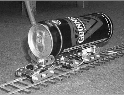
The mechanical engineering project runs between week two and week nine of the academic year (eight weeks in total). The groups are required to design and construct a lightweight model railcar to safely carry a payload as quickly as pos-sible along a standard racecourse. The railcar must meet the following specifica-tions (Fig 1):
• Capable of running on O-gauge track (i.e. rails set a distance of 33 mm apart)
• The overall width and height above the rails must not exceed 80 and 120 mm, respectively
• Capable of safely transporting a 526g payload (standard 500-ml beer can)
• Must be self-propelled and capable of climbing and descending a 5 % gradient and negotiating a curve 0.8 m in radius
[image:3.473.138.336.450.603.2]• A target budget of about €20.00, in total
The groups are given requirements for the submission of work to the Me-chanical Engineering workshop and a timeline over which the project is to run. During the first week of the project, the students refresh their skills in using AutoCAD by producing engineering drawings of standard MECCANO parts. During the second week, the students are given some instruction during a one-hour introductory lecture, highlighting the critical design issues; what calcula-tions are required; trade-offs and financial implicacalcula-tions and what disasters to avoid. During the third week, the groups work in their own time to prepare a de-sign concept which they present to their peers and colleagues in the fourth week for critical discussion.
Between week five and week seven, the groups complete the design and as-semble the railcars, which they can test and modify as necessary. Detailed design drawings and a bill of quantities are prepared by the students under the guidance of the trained demonstrators. Any components that must be manufactured are submitted to the Mechanical Engineering workshop. The students are made aware of the practical problems that can arise from poor design and assembly. A full design portfolio is prepared by the group and submitted along with the railcar at the end of week seven.
During the eight and final week, all of the railcars are timed over a standard racecourse and given a performance rating (R1, see Eq. 1) based on the time pe-riod that is taken to complete the racecourse and the rated power.
(
*)
max * /V
V
R1 = 2 + 8 (1)
I L
V = (2)
3 P
t
I = (3)
where V* is the railcar speed;
V*max is the handicap speed measured for the fastest railcar; L is the length of the racecourse;
I is a performance index;
t is the time period taken to complete the racecourse; and P is the installed power.
The students are provided with extensive documentation (covering the issues that have to be addressed) through the course website on the College intranet, including links to suppliers and to the inventories of components that are avail-able in house. There are also drawings of standard wheel-sets, the payload that must be carried and a spreadsheet for transmission optimization.
for the groups to design a railcar that they themselves can assemble using hand tools. The groups may also design components which are manufactured to their drawings in the workshop (time permitting) but the students must still complete the final assembly themselves.
The solution adopted is to make it possible for the railcar to be built from MECCANO but to encourage the students to think about alternative and poten-tially better ways of meeting the specification. In this way, all of the groups have a good chance of producing a working railcar but the more inventive can go be-yond the safety net provided to produce a more innovative design. Whilst most of the groups use MECCANO as the main construction material, some use other construction kits such as Lego and others use rather unconventional chassis con-structions fabricated, for example, using balsa wood or cardboard. Other groups design components to be made out of aluminum sheet and extruded sections that are assembled to create the railcar.
Careful attention must be given to the supply chain. Certain key components are not available off the shelf in Ireland (in particular the MECCANO parts and wheel-sets) and a stock must be ordered ahead of the project so that the compo-nents are available when required by the students. The students can order the components themselves, but unless they are particularly well organized, the de-livery delays mean that the components do not arrive in time. Although small electric motors and gears can be obtained off the shelf in Dublin, stocks are also ordered ahead of the project since there are often unpredictable delays (the only local supplier does not have a very effective stock control system). A supply of basic hand tools including spanners, screwdrivers and Allen keys is also made available to the students. All of this is financed by a system of cash deposits by the groups for the different components used and the deposit is returned later if the railcar is handed back to the department at the end of the project.
4. Civil engineering project
The civil engineering project runs between week 10 and week 16 of the aca-demic year (seven weeks in total). The racecourse track in the race competition includes a gap and the students are required to design and construct a model bridge that supports the track across the gap. The bridge must meet the following specifications:
• Clear span of 1.4 m and free standing with the ends of the bridge relying only on point-contact support (i.e. no horizontal reaction)
• Bridge deck must be continuous and at least 80-mm in width (to ac-commodate the rail track which can not be relied on for strength) and must rise at a slope gradient of 1:20
• The top of the deck and the bridge supports at either end must be flush to allow a smooth transition for the track
• Bridge must allow the passage of the railcar and its payload which to-gether could be up to 100 and 150 mm in width and in height, respec-tively
• Any construction materials can be used but the total mass of the bridge must be less than 350 g
• Capable of carrying a worst-case scenario load of 1.5 kg placed at its mid-span without appreciable deformation occurring.
The groups are given a timeline over which the project is to run and submis-sion deadlines for the different coursework. The students in each group appoint a project manager who is the principal point of contact between the professor and the group. The project manager is also responsible for submitting the coursework punctually. The students are provided with tutorial reading material but are also required to seek additional information from recommended sources themselves.
After some instruction on the merits and limitations of the different design options, the groups work in their own time during the first week of the project to prepare a bridge design concept. The bridge should in essence be a truss design so that all of the groups have a good chance of producing a working model but the more inventive can go beyond the safety net provided to produce a more in-novative design.
Whilst most of the groups use balsa wood as the main construction material, some use plastic sheet or tubing, cardboard, expanded polystyrene or aluminum sheet. The structural members are generally secured together using pin connec-tions or adhesive glues. The capacity of the Civil Engineering workshop is also very limited so that the groups must source the materials and build the models themselves using their own hand tools.
force analysis, materials, etc.) to peers and colleagues in a class session for criti-cal discussion and feedback. At this stage, the groups cannot change the basic design concept but may make some minor changes based on the feedback re-ceived.
Between week three and week five, the groups carry out a numerical analysis under the guidance of a professor in order to assess the load–deflection behavior of the proposed bridge. In the third week, the students are introduced to STAAD Pro-QSE [1] frame analysis program during a one-hour tutorial session following which the students work through a real problem (analysis of a structural-steel roof truss for a supermarket) to become more familiar with the software package. The groups are required to develop a plain-strain model of the proposed bridge (simply supported structure with either pinned and/or fixed connections between the individual members depending on the construction) and its load–deflection performance is analyzed during the fourth and fifth weeks. The students must research the pertinent engineering properties of the materials for input to the nu-merical analysis. The groups optimize their designs by changing the geometrical arrangement, material and/or sectional properties of the constituent members in order to limit the predicted deflection under the worst-case scenario load condi-tion of 1.5 kg placed above the bridge-deck at mid-span.
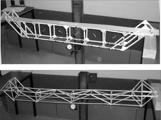
[image:7.473.104.370.399.598.2]During the sixth week, the groups build the physical models, which are later tested during a laboratory session before their peers and colleagues during week seven. The mass (m) of the model is measured and the bridge is checked against the specifications. The actual deflection (δ) of the bridge under a static 1.5 kg load placed above the deck at mid-span is measured using a dial gauge (Fig 2).
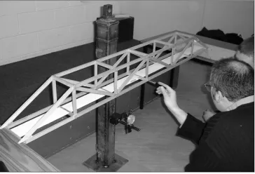
The students are made personally aware of the ways in which the designs can be improved and the practical problems that can arise from poor design and construction (Fig 3). The bridges are assigned a performance rating (R2, see Eq. 4) based on having the lightest model and the least deflection. The lower the R2 value the better the performance of the model according to these criteria.
δ 2
2 m
R = (4)
[image:8.473.146.328.288.412.2]A full design portfolio is prepared by the group and submitted at the end of seventh and final week of the civil engineering project. Each student is required to clearly state his or her degree of involvement in the coursework elements of the group. A project report including an explanation of the reasons for choosing the design and its novel features; the engineering properties of the materials; the approach used in modeling the bridge; the input parameters and the results of the numerical analysis; the manufacture of the physical model and its predicted and measured mid-span deflections.
Fig. 3. Critical feedback on bridge design 5. Electronic engineering project
The electronic engineering project runs between week 17 and week 24 of the academic year (eight weeks in total) with the groups attending a two-hour labora-tory practical during each week of the project. The students are introduced to the challenges of electronic systems design and are required to apply and develop the knowledge lectured in the Electronics course on the B.A.I. degree program. The project is an example of ‘hardware and software co-design’ and the scale of the task is such that it requires teamwork as a coordinated effort.
on-board PICAXE® [2] programmable micro controller that allows the railcar to be steered and driven either forward or in reverse. The railcar senses its location using switches on its bumpers and can follow a line that has been traced out on the floor by using sets of infrared optical sensors. The sensor signals are con-nected as inputs to the micro controller.
The groups must build their circuits (wiring and soldering on breadboard) and the students are made personally aware of the health and safety issues asso-ciated with electronic circuit construction and the adoption of test procedures by trained demonstrators. A full design portfolio is submitted by the groups along with a demonstration of the constructed circuit during the final week of the pro-ject.
6. Final race competition
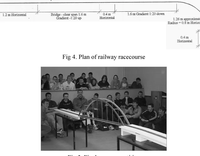
[image:9.473.71.390.349.597.2]The groups that have developed the ten fastest railcars and the ten best bridges (ranked in order of performance rating) compete in a competitive race at the end of the academic year. The teams are formed by pairing the railcars and the bridges using a lottery system. The railcars are timed along a 6.4 m race-course that includes a curve in the track a 5 % upward and downward gradient and the bridges (Fig 4). A prize fund is awarded to the teams that complete the racecourse in the fastest time period (Fig 5).
Fig 4. Plan of railway racecourse
[image:9.473.134.339.452.590.2]7. Assessment
The Engineering Design course is continuously assessed by coursework. There are no formal end-of-year examinations. The students are advised that the overall mark awarded to the group on completing the course is calculated as fol-lows:
Group mark (%) =
(
A.B.C)
+(
A+B+C)
3 2 3
1 13
(5)
where A, B and C are the percentage marks awarded for the mechanical, civil and electronic engineering projects, as set out in Table 1.
Credit is also given to the more inventive groups that go beyond the safety net provided to produce more innovative designs.
Table 1. Assessment of project portfolios
Mechanical Engineering Project A Mark (%)
AutoCAD drawing (students assessed
individually) 20
Presentation of concept design 30 Performance rating of railcar 10 Design portfolio including model railcar 40 100
Civil Engineering Pproject B Mark (%)
Presentation of concept design 15 Numerical analysis 20 Quality of physical model 15 Performance rating of bridge 10 Design portfolio and level of difficulty of
design 40
100
Electronic Engineering Project C Mark (%)
Hardware construction 24
Software design 24
System testing 22
Design portfolio 30
100
group. A satisfactory mark must be obtained by the student in each of the three projects as well as an overall course mark of at least 40 % to successfully pass the course.
8. Discussion
The Engineering Design course has placed the students in the center of the learning process with the learning responsibility having largely moved to the students from the teachers (act primarily as facilitators). The projects serve as an engine for invention to assist the students in achieving a range of professional, transferable and social competences. The project specifications are such that all of the groups have a good chance of producing working models but the more inventive can go beyond the safety net provided to produce more innovative de-signs.
There is a high degree of focus on the development of communication skills, learning competence and the ability to work in interdisciplinary settings, project management and team-building skills, information technology skills, as well as further development of the confidence and self-esteem of the students. The com-petences are assessed by the teachers through the project portfolios (oral presen-tations, working models and common reports) in order to validate the process.
The motivation among the students is high (as evident from the amount of time that they spend working on the projects) and considerable enthusiasm and interaction is generated among the students with about 95 % student participation achieved.
9. Summary and conclusions
An interdisciplinary problem-based Engineering Design course taken by about 170 students in the second year of a Bachelor of Engineering degree pro-gram has been described. Working groups of typically four or five students of mixed ability are given written specifications, a timeline and submission dead-lines for civil, mechanical and electronic engineering projects. The projects serve as an engine for invention to assist the students in achieving a range of profes-sional, transferable and social competences with the learning responsibility hav-ing largely moved to the students from the teachers who now acthav-ing primarily as facilitators.
The students must work effectively in groups to formulate, analyze, optimize and evaluate the performance of their design solutions and communicate their ideas effectively under the guidance of a team of professors and demonstrators. The project specifications are such that all of the groups have a good chance of producing working models but the more inventive can go beyond the safety net provided to produce more innovative designs.
plurality of solutions. The motivation among the students is high and consider-able enthusiasm and interaction is generated among the students. The students are continuously examined by the teachers and the competences are assessed through full project portfolios.
References
[1] STAAD PRO-QSE, Research Engineers International. Available from http://www.
reel.co.uk.