(1) (2)
(3) (4)
(5)
(6)
(7)
(8)
(9)
(10)
(11) Fig. 1
VSV for CCV
VSV for EVAP
ECM
Vapor Pressure Sensor
Fuel Tank Over Fill Check Valve
Fuel Tank Charcoal Canister
VSV for Pressure Switching Valve
A73631
358
Author: Date:
2004 COROLLA (RM1037U)
DTC
P0441
EVAPORATIVE EMISSION CONTROL
SYSTEM INCORRECT PURGE FLOW
DTC
P0446
EVAPORATIVE EMISSION CONTROL
SYSTEM VENT CONTROL CIRCUIT
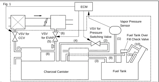
CIRCUIT DESCRIPTION
The vapor pressure sensor,VSV for canister closed valve (CCV), VSV for pressure switching valve are used to detect abnormalities in the evaporative emission control system.
The ECM decides whether there is an abnormality in the evaporative emission control system based on the vapor pressure sensor signal.
[image:1.595.42.556.302.569.2]A73632
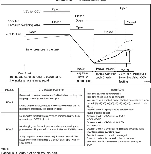
VSV for CCV
VSV for
Pressure Switching Valve
VSV for EVAP
Cold Start
Temperatures of the engine coolant and the intake air are almost equal.
Negative Pressure Introduction
Tank & Canister Leak Check
VSV for Pressure Switching Valve, CCV Testing Open Closed Open Closed Open Closed Closed Closed Open
P0441 P0442, P0456 P0446 Inner pressure in the tank
DTC No. DTC Detecting Condition Trouble Area
P0441
Pressure in charcoal canister and fuel tank does not drop dur-ing purge control (2 trip detection logic)
Fuel tank cap incorrectly installed Fuel tank cap is cracked or damaged
Vacuum hose is cracked, holed, blocked, damaged or discon-P0441
During purge cut–off, pressure is very low compared with at-mospheric pressure (2 trip detection logic)
, , , g
nected ((1), (2),(3), (4), (5), (6), (7), (8), (9), (10) and (11) in Fig. 1)
Open or short in vapor pressure sensorcircuit V
No rising the fuel tank pressure when commanding the CCV open after an EVAP leak test
Vapor pressure sensor
Open or short in VSV circuit for EVAP VSV for EVAP
Open or short in VSV circuit for CCV P0446
No changing the fuel tank pressure when commanding the pressure switching valve for the check after the EVAP leak test
Open or short in VSV circuit for CCV VSV for CCV
Open or short in VSV circuit for pressure switching valve VSV for pressure switching valve
A high negative pressure (vacuum) does not occurs in the system when commanding the VSV for EVAP open with the CCV closed
VSV for ressure switching valve Fuel tank is cracked, holed or damaged Charcoal canister is cracked, holed or damaged Fuel tank over fill check valve is cracked or damaged ECM
HINT:
Typical DTC output of each trouble part.
Trouble part Typical DTC output (*1) Small Leak P0442 and/or P0456 (*2) Medium Leak (ex: Vacuum hose loose) P0442
Large Leak (ex: Fuel tank cap loose) P0441 and P0442 and P0446 VSV for EVAP
Open Malfunction P0441
VSV for EVAP
Close Malfunction P0441 and P0442 and P0446 VSV for CCV
[image:2.595.37.556.59.589.2]360
Author: Date:
2004 COROLLA (RM1037U)
MONITOR DESCRIPTION
P0441
The ECM checks for a stuck closed malfunction in the VSV for EVAP by commanding it to open with the CCV closed. If a high negative pressure does not develop inthe fuel tank, the ECM determines that the VSV for EVAP remains closed. The ECM turns on the MIL and a DTC is set.
The ECM checks for VSV for EVAP ”stuck open” fault by commanding both valves (VSV for EVAP and CCV) to close at a time when the fuel tank is at atmospheric pressure. If the fuel tank develops a high negative pressure at this early stage of the test, the ECM determines that the VSV for EVAP is stuck OPEN. The ECM will turn on the MIL and a DTC is set.
P0446
If there is a malfunction detected in the VSV for evaporative emission (EVAP), the canister closed valve (CCV) and the VSV for bypass valve; the ECM will illuminate the MIL and set a DTC.
This portion of the EVAP diagnosis checks the following EVAP system functions: (a) CCV stuck closed.
The ECM checks for a CCV ”stuck closed” malfunction by commanding the CCV to open after an EVAP leak test. If the fuel tank pressure does not rise (lose vacuum), the ECM determines that the CCV is stuck closed. The ECM will turn on the MIL and a DTC is set.
(b) VSV for pressure switching valve stuck closed.
The ECM checks for a VSV for pressure switching valve ”stuck closed” malfunction by commanding the VSV for pressure switching valve to close after an EVAP leak test. If the fuel tank pressure does not change, the ECM determines that the VSV for pressure switching valve is malfunctioning. The ECM will turn on the MIL and a DTC is set.
(c) VSV for EVAP (Purge line to intake manifold) stuck closed.
The ECM checks for a stuck closed malfunction in the VSV for EVAP by commanding it to open with the CCV closed. If a high negative pressure does not develop inthe fuel tank, the ECM determines that the VSV for EVAP remains closed. The ECM turns on the MIL and a DTC is set.
MONITOR STRATEGY
P0441 VSV for EVAP malfunction DTCs
P0446
Canister close valve stuck closed
VSV for pressure switching valve malfunction VSV for EVAP malfunction
Main Vapor pressure sensor Required sensors/components
Sub Engine coolant temperature sensor, intake air temperature sensor, vehicle speed sensor Frequency of operation Once per drive cycle
TYPICAL ENABLING CONDITIONS
Item Criteria
Item
Minimum Maximum
The monitor will run whenever the
follow-ing DTCs are not present See ”List of Disable a Monitor” (On page 05–25) The same as that for DTC P0442
TYPICAL MALFUNCTION THRESHOLDS
P0441
Detection Criteria Threshold
Following conditions (a) and (b) are met: – (a) Fuel tank pressure is –1.6 kPa (–12 mmhg) or more at
the vacuum introduction start –
(b) Difference between the fuel tank pressures at the
vacu-um introduction start and completion Less than 0.9 kPa (7 mmHg) Following conditions are met for 14 seconds A and B
A. Difference between ”minimum fuel tank pressure before leak check” and ”fuel tank pressure when 14seconds after leak check”
0.5 kPa or more (3.5 mmHg) B. Fuel tank pressure at 14 seconds after leak check Less than – 3.7 kPa (–28 mmHg)
P0446
Detection Criteria Threshold
Case 1: CCV stuck closed
Fuel tank pressure when the CCV is opened after an EVAP
leak check Not changing
Case 2: VSV for pressure switching valve malfunction Fuel tank pressure when the VSV for bypass valve is closed
after an EVAP leak check Not changing
Case 3: VSV for EVAP stuck closed
Fuel tank pressure after the VSV for EVAP is opened and
manifold vacuum is introduced to the fuel tank Not changing
MONITOR RESULT (MODE 06 DATA)
Test ID Comp ID Description of Test Data Description of Test Limit Unit Conversion Factor $81 Tank pressure change value
dur-ing vacuum introduction
Malfunction criteria for VSV for
EVAP mmHg
Multiply by 0.0916
$82
Fuel tank pressure change value at switching over the canister close valve or VSV for pressure switching valve.
Malfunction criteria for canister close valve and VSV for pressure
switching valve
mmHg
Multiply by 0.0458 minus
2.930 $02
$03
Fuel tank pressure change 5 se-conds after the end the vacuum introduction cycle
Conditions:
Malfunction criteria for 0.040 leak mmHg Multiply by 0.0458
$04
Conditions:
VSV for EVAP: Closed
EFI Relay A84930 ECM VC E3 18 Y J2 J3 Junction Connector D B Y 16 II2 Y 6 Y 3 V 4
Vapor Pressure Sensor
L 2 E6 L 21 PTNK E2 28 E3 BR F J 3 Junction Connector F BR 7 BR 1 ID2 BR 1 2 Ignition Switch B IM 6 IM 3 5 6 IG2 AM2 IL 5 IC 12 B–W Instrument Panel J/B B–W B–W EA1 10 B–W EA1 3 Instrument Panel J/B AM2 IA4 2 B–R B–R R–W
1 1 1 1
1 5 3 2 1 1 1A 1 2 1 1 2 MAIN EFI B–W FL MAIN Battery B EA1 9 B W–B B ED Engine Rome J/B and R/B B ID2 7 II1 6
B B 4B1
4B
2 3 4B
B B Center J/B II2 17 ID2 8 CCV 1 E5 EVP 12 E3 TBP 4 E6 +B 1 E6 R R B 2 1 L–B 2 1 L 2 1 B B L V 2
VSV (Canister Closed Valve)
V 3
VSV (EVAP)
V 5
VSV (Vaper Pressure Sensor) ID2
ID2
II2
362
Author: Date:
2004 COROLLA (RM1037U)
INSPECTION PROCEDURE
HINT:
If DTC P0441 (Purge Flow), P0446 (VSV for CCV or VSV for Pressure switching valve), P0451, P0452 or P0453 (See page 05–242) is output with DTC P0442 or P0456 (See page 05–218), first trouble-shoot DTC P0441, P0446, P0451, P0452 or P0453. If no malfunction is detected, troubletrouble-shoot DTC P0442 or P0456 next.
Read freeze frame data using the hand–held tester or the OBD II scan tool. Freeze frame data records the engine conditions when a malfunction is detected. When troubleshooting, it is useful for determin-ing whether the vehicle was runndetermin-ing or stopped, the engine was warmed up or not, the air–fuel ratio was lean or rich, etc. at the time of the malfunction.
When the ENGINE RUN TIME in the freeze frame data is less than 200 seconds, carefully check the vapor pressure sensor.
Hand–held Tester:
1
CHECK FUEL TANK CAP ASSY(CHECK THAT FUEL TANK CAP IS TOYOTA
GENUINE PARTS)
NG REPLACE TO TOYOTA GENUINE PARTS
OK
2
CHECK THAT FUEL TANK CAP IS CORRECTLY INSTALLED
NG CORRECTLY INSTALL FUEL TANK CAP
OK
3
INSPECT FUEL TANK CAP ASSY (See page
12–1
)
NG REPLACE FUEL TANK CAP ASSY
OK
4
CHECK FILLER NECK FOR DAMAGE
(a) Remove the fuel tank cap.
(b) Visually check the fuel inlet pipe for damage. (c) Reinstall the fuel tank cap.
A65767
VSV is OFF VSV is ON
Air Air
364
Author: Date:
2004 COROLLA (RM1037U)
5
PERFORM ACTIVE TEST BY HAND–HELD TESTER(CHECK FOR EVAP PURGE
FLOW)
(a) Select the item ”DIAGNOSIS/ENHANCED OBD II/AC-TIVE TEST” mode on the hand–held tester.
(b) Disconnect the vacuum hose of the VSV for EVAP from the charcoal canister.
(c) Start the engine.
(d) Select the item ”EVAP VSV (ALON)/ALL” in the ACTIVE TEST and operate EVAP VSV (Press the right or left but-ton).
(e) When the VSV for the EVAP is operated by the hand–held tester, check whether the disconnected hose applies suc-tion to your finger.
Result:
VSV is ON: Disconnected hose sucks.
VSV is OFF: Disconnected hose does not suck.
(f) Reconnect the vacuum hose.
OK Go to step 9
NG
6
CHECK VACUUM HOSES(INTAKE MANIFOLD – VSV FOR EVAP, VSV FOR EVAP –
CHARCOAL CANISTER)
(a) Check that the vacuum hose is connected correctly. (b) Check the vacuum hose for looseness and disconnection. (c) Check the vacuum hose for cracks, hole, damage and blockage.
NG REPAIR OR REPLACE VACUUM HOSE
OK
7
INSPECT VSV FOR EVAP(OPERATION) (See page
12–1
)
NG REPLACE VSV FOR EVAP
A51984 A52933
Wire Harness Side:
VSV for EVAP Connector V3
Front View
A65743
EVP E3
ECM Connector
A65750
Engine Room R/B:
EFI Relay
8
CHECK HARNESS AND CONNECTOR(EFI RELAY – VSV FOR EVAP, VSV FOR
EVAP – ECM)
(a) Check the harness and the connector between the VSV for EVAP and the ECM.
(1) Disconnect the V3 VSV for EVAP connector. (2) Disconnect the E3 ECM connector.
(3) Check the resistance between the wire harness side connectors.
Standard (Check for open):
Tester Connection Specified Condition VSV for EVAP (V3–1) – EVP (E3–12) Below 1 Ω
Standard (Check for short):
Tester Connection Specified Condition VSV for EVAP (V3–1) or EVP (E3–12) – Body ground 10 kΩ or higher
(4) Reconnect the VSV for EVAP connector. (5) Reconnect the ECM connector.
(b) Check the harness and the connector between the VSV for EVAP and the EFI relay.
(1) Disconnect the V3 VSV for EVAP connector. (2) Remove the EFI relay from the engine room R/B. (3) Check the resistance between the wire harness
side connectors.
Standard (Check for open):
Tester Connection Specified Condition VSV for EVAP (V3–2) – EFI relay (3) Below 1 Ω
Standard (Check for short):
Tester Connection Specified Condition VSV for EVAP (V3–2) or EFI relay (3) – Body ground 10 kΩ or higher
(4) Reconnect the VSV for EVAP connector. (5) Reinstall the EFI relay.
NG REPAIR OR REPLACE HARNESS OR
CONNECTOR
OK
A65768
VSV is OFF VSV is ON
Air Air
E
F
E
F
366
Author: Date:
2004 COROLLA (RM1037U)
9
PERFORM ACTIVE TEST BY HAND–HELD TESTER(VSV FOR CCV)
(a) Disconnect the vacuum hose of the VSV for CCV from the charcoal canister.
(b) Start the engine.
(c) Select the item ”DIAGNOSIS/ENHANCED OBD II/AC-TIVE TEST” mode on the hand–held tester.
(d) Select the item ”CAN CTRL VSV/ALL” in the ACTIVE TEST and operate CAN CTRL VSV (Press the right or left button).
(e) Check the VSV operation when it is operated by the hand–held tester.
Result:
VSV is ON: Air from port E flows out through port F. VSV is OFF: Air does not flow from port E to port F.
OK Go to step 13
NG
10
CHECK VACUUM HOSES(VSV FOR CCV – CHARCOAL CANISTER)
(a) Check that the vacuum hose is connected correctly. (b) Check the vacuum hose for looseness and disconnection. (c) Check the vacuum hose for cracks, hole, damage and blockage.
NG REPAIR OR REPLACE VACUUM HOSES
OK
11
INSPECT VSV FOR CCV(OPERATION) (See page
12–6
)
NG REPLACE VSV FOR CCV
A54386
Wire Harness Side:
VSV for CCV Connector
V2
Front View
A65744
CCV
ECM Connector E5
A65750
Engine Room R/B:
EFI Relay
12
CHECK HARNESS AND CONNECTOR(EFI RELAY – VSV FOR CCV, VSV FOR CCV
– ECM)
(a) Check the harness and connector between the VSV for CCV and ECM.
(1) Disconnect the V2 VSV for CCV connector. (2) Disconnect the E5 ECM connector.
(3) Check the resistance between the wire harness side connectors.
Standard (Check for open):
Tester Connection Specified Condition VSV for CCV (V2–1) – CCV (E5–1) Below 1 Ω
Tester Connection Specified Condition VSV for CCV (V2–1) or CCV (E5–1) – Body ground 10 kΩ or higher
(4) Reconnect the VSV for CCV connector. (5) Reconnect the ECM connector.
(b) Check the harness and the connector between the VSV for CCV and the EFI relay.
(1) Disconnect the V2 VSV for CCV connector. (2) Remove the EFI relay from the engine room R/B. (3) Check the resistance between the wire harness
side connectors.
Standard (Check for open):
Tester Connection Specified Condition VSV for CCV (V2–2) – EFI relay (3) Below 1 Ω
Standard (Check for short):
Tester Connection Specified Condition VSV for CCV (V2–2) or EFI relay (3) – Body ground 10 kΩ or higher
(4) Reconnect the VSV for CCV connector. (5) Reinstall the EFI relay.
NG REPAIR OR REPLACE HARNESS OR
CONNECTOR
OK
Air
E
F Air
E
F
VSV is ON VSV is OFF
A52984
368
Author: Date:
2004 COROLLA (RM1037U)
13
PERFORM ACTIVE TEST BY HAND–HELD TESTER(VSV FOR PRESSURE
SWITCHING VALVE)
(a) Select the item ”DIAGNOSIS/ENHANCED OBD II/AC-TIVE TEST” mode on the hand–held tester.
(b) Select the item ”TANK BYPASS VSV/ALL” in the ACTIVE TEST and operate TANK BYPASS VSV (Press the right or left button).
(c) Check the VSV operation when it is operated by the hand–held tester.
Result:
VSV is ON: Air from port E flows out through port F. VSV is OFF: Air does not flow from port E to port F.
OK Go to step 16
NG
14
INSPECT VSV FOR PRESSURE SWITCHING VALVE(OPERATION)
NG REPLACE VSV FOR PRESSURE SWITCHING
VALVE
A72890
Wire Harness Side:
VSV for Pressure Switching Valve
V5
Front View
A65748
ECM Connector E6
TBP
A65750
Engine Room R/B:
EFI Relay
15
CHECK HARNESS AND CONNECTOR(EFI RELAY – VSV FOR PRESSURE
SWITCHING VALVE, VSV FOR PRESSURE SWITCHING VALVE – ECM)
(a) Check the harness and the connector between the VSV for pressure switching valve and the ECM.
(1) Disconnect the V5 VSV for pressure switching valve connector.
(2) Disconnect the E6 ECM connector.
(3) Check the resistance between the wire harness side connectors.
Standard (Check for open):
Tester Connection Specified Condition VSV for pressure switching valve (V5–1) – TBP (E6–4) Below 1 Ω
Standard (Check for short):
Tester Connection Specified Condition VSV for pressure switching valve (V5–1) or TBP (E6–4)
– Body ground 10 kΩ or higher
(4) Reconnect the VSV for pressure switching valve connector.
(5) Reconnect the ECM connector.
(b) Check the harness and the connector between the VSV for pressure switching valve and the EFI relay.
(1) Disconnect the V5 VSV for pressure switching valve connector.
(2) Remove the EFI relay from the engine room R/B. (3) Check the resistance between the wire harness
side connectors.
Standard (Check for open):
Tester Connection Specified Condition VSV for pressure switching valve (V5–2) – EFI relay (3) Below 1 Ω
Standard (Check for short):
Tester Connection Specified Condition VSV for pressure switching valve (V5–2) or EFI relay (3)
– Body ground 10 kΩ or higher
(4) Reconnect the VSV for pressure switching valve connector.
(5) Reinstall the EFI relay.
NG REPAIR OR REPLACE HARNESS OR
CONNECTOR
OK
A10193
A65741
VC (+)
E2 (–) E3
ECM Connector
370
Author: Date:
2004 COROLLA (RM1037U)
16
CHECK FOR EVAPORATIVE EMISSIONS LEAK(NEAR FUEL TANK)
(a) Check whether hoses close to the fuel tank have been modified, and check if there are signs of any accident near the fuel tank.
(1) Check the following parts for cracks, deformation or loose connection:
Fuel tank
Fuel tank filler pipe
Hoses and tubes around fuel tank
NG REPAIR OR REPLACE EVAPORATIVE
EMISSIONS LEAK PART
OK
17
CHECK VACUUM HOSES(VAPOR PRESSURE SENSOR – FUEL TANK,
CHARCOAL CANISTER – VSV FOR PRESSURE SWITCHING VALVE)
(a) Check that the vacuum hose is connected correctly. (b) Check the vacuum hose for looseness and disconnection. (c) Check the vacuum hose for cracks, hole and damage.
NG REPAIR OR REPLACE VACUUM HOSE
OK
18
CHECK HOSE AND TUBE(FUEL TANK – CHARCOAL CANISTER)
(a) Check the connection between the fuel tank and fuel EVAP pipe, the fuel EVAP pipe and under–floor fuel tube, the under–floor fuel tube and charcoal canister.
(b) Check the hose and the tube for cracks, hole and damage.
NG REPAIR OR REPLACE HOSE AND TUBE
OK
19
INSPECT ECM(VC VOLTAGE)
(a) Turn the ignition switch ON.
(b) Measure the voltage between the terminals of the E3 ECM connector.
Standard:
Tester Connection Specified Condition VC (E3–18) – E2 (E3–28) 4.5 to 5.5 V
NG REPLACE ECM (See page 10–11)
A65741
E2 (–) PTNK (+)
E3 E6
A73630
Disconnect TYPE A
TYPE B
Vacuum Vacuum
Disconnect
A72886
Wire Harness Side:
Vapor Pressure Sensor Connector
GND PTNK VCC
V4
Front View
E6 E3
VC
20
INSPECT ECM(PTNK VOLTAGE)
(a) Turn the ignition switch ON.
(b) Measure the voltage between terminals of the E3 and E6 ECM connectors.
(1) Disconnect the vacuum hose from the vapor pres-sure sensor.
Standard (1):
Tester Connection Specified Condition PTNK (E6–21) – E2 (E3–28) 2.9 to 3.7 V
NOTICE:
The vacuum applied to the vapor pressure sensor must be less than 66.7 kPa (500 mmHg, 19.7 in.Hg).
(2) Using the MITYVAC (Hand–held Vacuum Pump), apply a vacuum of 4.0 kPa (30 mmHg, 1.18 in.Hg) to the vapor pressure sensor.
Standard (2):
Tester Connection Specified Condition PTNK (E6–21) – E2 (E3–28) 0.5 V or less
(3) Reconnect the vacuum hose.
OK Go to step 22
NG
21
CHECK HARNESS AND CONNECTOR(VAPOR PRESSURE SENSOR – ECM)
(a) Disconnect the V4 vapor pressure sensor connector. (b) Disconnect the E3 and E6 ECM connectors.
(c) Check the resistance between the wire harness side con-nectors.
Standard (Check for open):
Tester Connection Specified Condition PTNK (V4–2) – PTNK (E6–21)
GND (V4–1) – E2 (E3–28) Below 1 Ω VCC (V4–3) – VC (E3–18)
Standard (Check for short):
Tester Connection Specified Condition PTNK (V4–2) or PTNK (E6–21) – Body ground
10 kΩor higher VCC (V4–3) or VC (E3–18) – Body ground 10 kΩ or higher
372
Author: Date:
2004 COROLLA (RM1037U)
REPLACE ECM (See page 10–11)
22
INSPECT FUEL TANK INLET VALVE ASSY
NG REPLACE FUEL TANK INLET VALVE ASSY
OK
23
INSPECT FUEL TANK ASSY
NG REPLACE FUEL TANK ASSY
OK
24
INSPECT CHARCOAL CANISTER ASSY(CRACKS, HOLE AND DAMAGE)
NG REPAIR OR REPLACE CHARCOAL CANISTER
ASSY
OK
REPLACE ECM (See page 10–11)
OBDII scan tool (excluding Hand–held Tester):
1
CHECK FUEL TANK CAP ASSY(CHECK THAT FUEL TANK CAP IS TOYOTA
GEHUINE PARTS)
NG REPLACE TO GENUINE PARTS
OK
2
CHECK THAT FUEL TANK CAP IS CORRECTLY INSTALLED
NG CORRECTLY INSTALL FUEL TANK CAP
OK
3
INSPECT FUEL TANK CAP ASSY (See page
12–1
)
NG REPLACE FUEL TANK CAP ASSY
A10193
4
CHECK FILLER NECK FOR DAMAGE
(a) Remove the fuel tank cap.
(b) Visually check the fuel inlet pipe for damage.
NG REPLACE FUEL TANK INLET PIPE SUB–ASSY
OK
5
CHECK FOR EVAPORATIVE EMISSIONS LEAK(NEAR FUEL TANK OR CHACOAL
CANISTER)
(a) Check whether hoses close to the fuel tank have been modified, and check if there are signs of any accident near the fuel tank or the charcoal canister.
(1) Check the following parts for cracks, deformation or loose connection:
Fuel tank
Charcoal canister
Fuel tank filler pipe
Hoses and tubes around fuel tank and char-coal canister
NG REPAIR OR REPLACE EVAPORATIVE
EMISSIONS LEAK PART
OK
6
CHECK VACUUM HOSES(VAPOR PRESSURE SENSOR – FUEL TANK,
CHARCOAL CANISTER – VSV FOR PRESSURE SWITCHING VALVE)
(a) Check that the vacuum hose is connected correctly. (b) Check the vacuum hose for looseness and disconnection. (c) Check the vacuum hose for cracks, hole and damage.
NG REPAIR OR REPLACE VACUUM HOSE
OK
7
CHECK HOSE AND TUBE(FUEL TANK – CHARCOAL CANISTER)
(a) Check the connection between the fuel tank and fuel EVAP pipe, the fuel EVAP pipe and under floor fuel tube , the under floor fuel tube and charcoal canister.
(b) Check the hose and the tube for cracks, hole and damage.
A65741
VC (+)
E2 (–) E3
ECM Connector
374
Author: Date:
2004 COROLLA (RM1037U)
8
CHECK VACUUM HOSES((5), (6), (7), (8) AND (9) IN FIG. 1 IN CIRCUIT
DESCRIPTION)
(a) Check that the vacuum hose is connected correctly. (b) Check the vacuum hose for looseness and disconnection. (c) Check the vacuum hose for cracks, hole and damage.
NG REPAIR OR REPLACE VACUUM HOSES
OK
9
CHECK EACH VSV CONNECTOR FOR LOOSENESS AND DISCONNECTION(VSV
FOR EVAP, VSV FOR CCV, VSV FOR PRESSURE SWITCHING VALVE)
NG REPAIR OR CONNECT VSV AND SENSOR
CONNECTOR
OK
10
INSPECT CHARCOAL CANISTER ASSY(CRACKS, HOLE AND DAMAGE)
NG CHECK AND REPLACE CHARCOAL CANISTER
ASSY
OK
11
INSPECT ECM(VC VOLTAGE)
(a) Turn the ignition switch ON.
(b) Measure voltage between the terminals of the E3 ECM connector.
Standard:
Tester Connection Specified Condition VC (E3–18) – E2 (E3–28) 4.5 to 5.5 V
NG REPLACE ECM (See page 10–11)
A65741
E2 (–) PTNK (+)
E3 E6
A73630
Disconnect TYPE A
TYPE B
Vacuum Vacuum
Disconnect
12
INSPECT ECM(PTNK VOLTAGE)
(a) Turn the ignition switch ON.
(b) Measure the voltage between terminals of the E3 and E6 ECM connectors.
(1) Disconnect the vacuum hose from the vapor pres-sure sensor.
Standard (1):
Tester Connection Specified Condition PTNK (E6–21) – E2 (E3–28) 2.9 to 3.7 V
NOTICE:
The vacuum applied to the vapor pressure sensor must be less than 66.7 kPa (500 mmHg, 19.7 in.Hg).
(2) Using the MITYVAC (Hand–held Vacuum Pump), apply a vacuum of 4.0 kPa (30 mmHg, 1.18 in.Hg) to the vapor pressure sensor.
Standard (2):
Tester Connection Specified Condition PTNK (E6–21) – E2 (E3–28) 0.5 V or less
(3) Reconnect the vacuum hose from the vapor pres-sure sensor.
OK Go to step 14
A72886
Wire Harness Side:
Vapor Pressure Sensor Connector
GND PTNK VCC
V4
Front View
A79127
E6 E3
ECM Connector E2
VC
PTNK
A65741
E2 (–) EVP (+)
E3
A65767
VSV is ON VSV is OFF E
F
E
F
Air Air
376
Author: Date:
2004 COROLLA (RM1037U)
13
CHECK HARNESS AND CONNECTOR(VAPOR PRESSURE SENSOR – ECM)
(a) Disconnect the V4 vapor pressure sensor connector. (b) Disconnect the E3 and E6 ECM connectors.
(c) Check the resistance between the wire harness side con-nectors.
Standard (Check for open):
Tester Connection Specified Condition PTNK (V4–2) – PTNK (E6–21)
GND (V4–1) – E2 (E3–28) Below 1 Ω VCC (V4–3) – VC (E3–18)
Standard (Check for short):
Tester Connection Specified Condition PTNK (V4–2) or PTNK (E6–21) – Body ground
10 kΩor higher VCC (V4–3) or VC (E3–18) – Body ground 10 kΩ or higher
(d) Reconnect the vapor pressure sensor connector. (e) Reconnect the ECM connectors.
NG REPAIR OR REPLACE HARNESS OR
CONNECTOR
OK
REPLACE ECM (See page 10–11)
14
INSPECT VSV FOR EVAP(FUNCTION)
(a) Turn the ignition switch ON. (b) Check the VSV function.
(1) Connect between terminals EVP and E2 of the ECM connector (VSV ON).
VSV is ON:
Air from port E flows out through port F
(2) Disconnect between terminals EVP and E2 of the ECM connector (VSV OFF).
VSV is OFF:
Air does not flow port E to port F
OK Go to step 17
A51984 A52933
Wire Harness Side:
VSV for EVAP Connector
V3
Front View
A65743
EVP E3
ECM Connector
A65750
Engine Room R/B:
EFI Relay
15
INSPECT VSV FOR EVAP(OPERATION) (See page
12–6
)
NG REPLACE VSV FOR EVAP
OK
16
CHECK HARNESS AND CONNECTOR(EFI RELAY – VSV FOR EVAP, VSV FOR
EVAP – ECM)
(a) Check the harness and between the VSV for EVAP and the ECM connector.
(1) Disconnect the V3 VSV for EVAP connector. (2) Disconnect the E3 ECM connector.
(3) Check the resistance between the wire harness side connectors.
Standard (Check for open):
Tester Connection Specified Condition VSV for EVAP (V3–1) – EVP (E3–12) Below 1 Ω
Standard (Check for short):
Tester Connection Specified Condition VSV for EVAP (V3–1) or EVP (E3–12) – Body ground 10 kΩ or higher
(4) Reconnect the VSV for EVAP connector. (5) Reconnect the ECM connector.
(b) Check the harness and connector between the VSV for EVAP and the EFI relay.
(1) Disconnect the V3 VSV for EVAP connector. (2) Remove the EFI relay from the engine room R/B. (3) Check the resistance between the wire harness
side connectors.
Standard (Check for open):
Tester Connection Specified Condition VSV for EVAP (V3–2) – EFI relay (3) Below 1 Ω
Standard (Check for short):
Tester Connection Specified Condition VSV for EVAP (V3–2) or EFI relay (3) – Body ground 10 kΩ or higher
(4) Reconnect the VSV for EVAP connector. (5) Reinstall the EFI relay.
NG REPAIR OR REPLACE HARNESS OR
A53763
E2
CCV
A65768
VSV is ON VSV is OFF E
F
E
F
Air Air
378
Author: Date:
2004 COROLLA (RM1037U)
17
INSPECT VSV FOR CCV(FUNCTION)
(a) Turn the ignition switch ON. (b) Check the VSV function.
(1) Connect between terminals CCV and E2 of the ECM connector (VSV ON).
VSV is ON:
Air from port E flows out through port F
(2) Disconnect between terminals CCV and E2 of the ECM connector (VSV OFF).
VSV is OFF:
Air does not flow from port E to port F
OK Go to step 20
NG
18
INSPECT VSV FOR CCV(OPERATION) (See page
12–6
)
NG REPLACE VSV FOR CCV
A54386
Wire Harness Side:
VSV for CCV Connector
V2
Front View
A65750
Engine Room R/B:
EFI Relay
A65744
CCV
ECM Connector E5
19
CHECK HARNESS AND CONNECTOR(EFI RELAY – VSV FOR CCV, VSV FOR CCV
– ECM)
(a) Check the harness and the connector between the VSV for CCV and the ECM.
(1) Disconnect the V2 VSV for CCV connector. (2) Disconnect the E5 ECM connector.
(3) Check the resistance between the wire harness side connectors.
Standard (Check for open):
Tester Connection Specified Condition VSV for CCV (V2–1) – CCV (E5–1) Below 1 Ω
Standard (Check for short):
Tester Connection Specified Condition VSV for CCV (V2–1) or CCV (E5–1) – Body ground 10 kΩ or higher
(4) Reconnect the VSV for CCV connector. (5) Reconnect the ECM connector.
(b) Check the harness and the connector between the VSV for CCV and the EFI relay.
(1) Disconnect the V2 VSV for CCV connector. (2) Remove the EFI relay from the engine room R/B. (3) Check the resistance between the wire harness
side connectors.
Standard (Check for open):
Tester Connection Specified Condition VSV for CCV (V2–2) – EFI relay (3) Below 1 Ω
Standard (Check for short):
Tester Connection Specified Condition VSV for CCV (V2–2) or EFI relay (3) – Body ground 10 kΩ or higher
(4) Reconnect the VSV for CCV connector. (5) Reinstall the EFI relay.
NG REPAIR OR REPLACE HARNESS OR
CONNECTOR
OK
A65741
E2 TBP
E6 E3
VSV is ON VSV is OFF Air
E
F
Air
E
F
A52143
380
Author: Date:
2004 COROLLA (RM1037U)
20
INSPECT VSV FOR PRESSURE SWITCHING VALVE(FUNCTION)
(a) Turn the ignition switch ON. (b) Check the VSV function.
(1) Connect between terminals TBP and E2 of the ECM connector (VSV ON).
VSV is ON: Air from port E flows out through port F
(2) Disconnect between terminals TBP and E2 of the ECM connector (VSV OFF).
VSV is OFF: Air does not from flow port E to port F
OK Go to step 23
NG
21
INSPECT VSV FOR PRESSURE SWITCHING VALVE(OPERATION)
(See page
12–6
)
NG REPLACE VSV FOR PRESSURE SWITCHING
VALVE
A72890
Wire Harness Side:
VSV for Pressure Switching Valve
V5
Front View
A65748
ECM Connector E6
TBP
A65750
Engine Room R/B:
EFI Relay
22
CHECK HARNESS AND CONNECTOR(EFI RELAY – VSV FOR PRESSURE
SWITCHING VALVE, VSV FOR PRESSURE SWITCHING VALVE – ECM)
(a) Check the harness and the connector between the VSV for pressure switching valve and the ECM.
(1) Disconnect the V5 VSV for pressure switching valve connector.
(2) Disconnect the E6 ECM connector.
(3) Check the resistance between the wire harness side connectors.
Standard (Check for open):
Tester Connection Specified Condition VSV for pressure switching valve (V5–1) – TBP (E6–4) Below 1 Ω
Standard (Check for short):
Tester Connection Specified Condition VSV for pressure switching valve (V5–1) or TBP (E6–4)
– Body ground 10 kΩ or higher
(4) Reconnect the VSV for pressure switching valve connector.
(5) Reconnect the ECM connector.
(b) Check the harness and the connector between the VSV for pressure switching valve and EFI relay.
(1) Disconnect the V5 VSV for pressure switching valve connector.
(2) Remove the EFI relay from the engine room R/B. (3) Check the resistance between the wire harness
side connectors.
Standard (Check for open):
Tester Connection Specified Condition VSV for pressure switching valve (V5–2) – EFI relay (3) Below 1 Ω
Standard (Check for short):
Tester Connection Specified Condition VSV for pressure switching valve (V5–2) or EFI relay (3)
– Body ground 10 kΩ or higher
(4) Reconnect the VSV for pressure switching valve connector.
(5) Reinstall the EFI relay from.
NG REPAIR OR REPLACE HARNESS OR
CONNECTOR
OK
382
Author: Date:
2004 COROLLA (RM1037U)
23
INSPECT FUEL TANK INLET VALVE ASSY
NG REPLACE FUEL TANK INLET VALVE ASSY
OK
24
INSPECT FUEL TANK ASSY
NG REPLACE FUEL TANK ASSY
OK