ABSTRACT
SOFTWARE DEVELOP!.1ENT IANGUAGE
FOR TIlE BURROUGHS D1700
by Donald R. McCrea Durroughs Corporation Santa Barbara Plant Goleta, California
The Burroughs Bl700 is a small, general-purpose computer which 1s ea) dyna:nically microprograll:.l;lable, and (b) designed to support hundreds ot independent, special-purpose machine architectures. Each language that runs on the B1700 has its own interpreter. In keeping with this flexi-bility, a lan:;uage and underlying machine structure WC1'C (!(~signed to be
used for implementation of the operating system and for implementation of the different compilers. This 1s an ALGOL-like, GO To-fl'ee language which is e!ceant, and yet modest in its design. The underlying machine structure 1s highly stack-oriented. allowing re-entrancy, recursion. and up-level addressing.
Keywords: . software implementation language, procedure-oriented language, stack machine, microprogramm.in:.;, computer architecture, 01700, S-language, interpretation, GO TO-free
PROPRIETARY DATA
tile Information contained in this document is proprlet~ry to BUrrougbs Corporation. The infoTm~tion or this docum"nt l~ pot
to be shown. reproduced, or disclosed out$lde. BUffO!lr;nS
Corporation without written perrr.:3s:c!I cf the Pyent DdiSIM. ~. THIS DOCUMENT IS THE PRO:>ERTY OF AilD SHALL BE
SOFTWARE DEVELOPMENT LANGUAGE FOR THE
BURROUGHS B1700
by
Donald R. McCrea Burroughs Corporation
PROPRIE1ARY DATt\
The InfOrmation contained in this document is proprietalY to
Burroughs Corporation. The inforrr.ation or this document is not
to be shown, reproduced, or di~clo;;cd outside Burroughs
Corporation without written perrr.is-:.;on of the Patent Division. THIS DOCUMENT IS THE PROPE~TY OF AND SHALL BE RETURNED TO BURROUGHS CORPORATION. BURROUGHS PLACE.
SOFTWARE DEVELOPMENT LANGUAGE FOR THE
I. Introduction II. The SDL Language
A. "History
B. Language Form C. Data Structures D. Procedures E. Statements
F. Program Segmentation
BURROUGHS B1700
G. Definitional (Macro) Facility H. Conditional Compilation
I. Measurement and Debug Facilities
J.
Special Constructs K. EvaluationIII. Overview of the Burroughs B1700 IV. The SDL Machine
A. Stack Mechanism B. Opcode Structure
C. ~escriptor Formats
DO. Code Addressing E. Data Addressing
I. Parameter Passing--Returning of Values
J.
Special OperatorsV. Conclusion
VI. Acknowledgements
I. Introduction
The Burroughs B1700 is a small, general-purpose computer. It belongs to the class of computers containing, among others, the IBM 360/20, IBM System 3, NCR Century 100 and 200, and the Univac 9300. However, the· B1700 differs from the others in that (a) it is dynamically micro-programmable, and (b) it is designed to support hundreds of independent, special-purpose machine architectures, rather than one general-purpose architecture.
Each particular machine architecture is realized on a vertically micro-programmable B1700 processor by means of multiprogrammed interpreters. The general philosophy of the system is that each language that runs on the machine will have its own interpreter; i.e., the B1700 can be a "COBOL machine", a "FORTRAN machine", a "SNOBOL machine", an "APL machine", etc.
In keeping with this flexibility, a language (along with its interpreter) was designed to be used for implementation of the Master Control Program {MCP) and for implementation of the different compilers. This language "1s called the Software Development Language (or SDL) •
..
. SDL has so far been used ·~o implement the MCP; compile~s for SDL, COBOL, FORTRAN, BASIC, and the B1700 micro-language; and a sort package. Planned in the future are a Network Definition Language processor, an ALGOL
compiler, and a Data Base Management System.
II. The SDL Language A. History
The advantages of using a higher level language for system implementation are well documented in the literature (see Sammet, 1971; Corbato, 1969; or MIT, 1970). I~ fact, this use of a higher level language is merely in
kee~ing with a Burroughs precedent (see Lyle, 1971).
Using input from the different software groups that would be using SDL, the SOL language and underlying machine structure were designed in the
.
fall of 1969. In February, 1970, programming of a bootstrap version of the SOL compiler was begun by a four-man group working in Burroughs
Extended ALGOL (Burroughs, 1969a) on the B5500. By June, 1970, a working version of the compiler, as well as a functional simulator of the SDL machine, were available on the B5500 for initial program checkout. Sinc~
B. Language Form
The design philosophy of SDL was that it was to be "clean" and con-sistent (see Weinberg, 1971). Consequently, we attempted to avoid language features that:
1) require run-time routines to accomplish
.
.
·2) are "nic::-eties" that can actually be built from simpler features in the language (e.g., the DO-UNTIL statement)
3) we didn't feel we could implement well on a small machine 4} didn't "fit" (i.e., weren.'t needed to implement software)
The XPL language (McKeeman, 1970) appears to have excised from PLjI (Lucas, 1969) many of the PL/I features which fall into one of the above categories, and yet, retains those features which are best for compile-r writing (see Slimich, 1971). Hence, SDL was designed using XPL as a base.
SDL is an ALGOL-like language. Allowable data types in SDL are bit
~trings, character strings, and fixed (integer) numbers, as well as
single-dimensional arrays of these and structures of mixed data types. There are a number of exc~llent reasons for implementing a GO TO-free
language (these are best summed in Weinberg, 1971; see also Dijkstra, 1968); and so SDL contains no GO TO's (neither does the SDL machine). Control is handled with IF-THEN and IF-THEN-ELSE statements, CASE
C. Data Structures
SDL data types are minimal but, nevertheless, are designed to provide for a wide range of needs with as little overhead as possible. Included are only those data types which are necessary for operating system
and compiler development, and which we could implement well in a
small-machine environment without run-time routine overhead penalties. Specifically excluded because of their inutility to software programming are floating point and decimal data types.
There are three types of data in SDL: b~t strings (BIT), character strings (CHARACTER), and fixed (integer) numbers (FIXED). For example,
DECLARE A FIXED, B BIT(7),
(C,D) CHARACTER(l023);
declares A to be an integer number, B to be a bit string of length 7 bits, and C and D to be character strings of length 1023 bytes each.
These basic data types may be grouped in structures, or single-dimensional arrays, or combinations of these. For example,
DECLARE
01 At
02 Al(9) -SIT(3),
02 Al(3) FIXED,
02 A3(7) CHARACTER(l);
DECLARE
01 B(7) ,
02 Bl FIXED, 02 B2 BIT (37) ,
03 B2l BIT(34), 03 B22 BIT(3) , 02 B3 Character(5);
declares B to be an array, the elements example:
DECLARE
01 C BIT(8l),
02 Cl BIT(17),
02 C2(5) CHARACTER(l), 02 C3 FIXED;
of which are structures.
declares C to be a structure, one sub-item of which is an array. The
A data structure may be declared as a template in order that it may be applied to more than one data area. This is done with indexing combined with the "REMAPS BASE" declaration:
DECLARE
01 AREA REMAPS BASE CHARACTER(40), 02 AREAl BIT(8),
02 FILLER CHARACTER(30), 02 AREA2 CHARACTER(9);
Data items ~ay also re-describe other data items: DECLARE
A CHARACTER(80),
describes an BO-byte data area as a single unit (A) and as an aggregate of single-byte pieces (B).
Simple dynamic data items, whose size is computed at run time: DECLARE DYNMHC C BIT(MrB- 3);
can be used to avoid wasting unused bits. Although dynamic data items may not be structured, they may be re-described ("remapped") and thus provided with structure in this way.
Paged arrays allow the programmer to explicitly parameterize virtual storage:
DECLARE PAGED(64) D(1024) CHARACTER(sOO);
Here, D is a paged array of 1024 elements, each 500 bytes in length, with 64 elements per ~age. The SDL machine automatically keeps only as many pages in memory as will conveniently fit. Paging is on a demand basis.
In retrospect, it would be nice to have virtual strings; i.e., an
E. Statements
There are basically three types of statements in SDL: the assignment statement (considered to be an expression), the control statement
(including conditional, group, and case statements, and procedure calls), and the function statement (including input-output statements and
ot.hers) •
Expressions
SDL expressions are fairly rich in nature, allowing IF-THEN-ELSE, CASE, and intermediate assignment, as well as arithmetic, logical, relational, and string operators. All data type combinations are permissible:
There is no type conversion. In most cases, the data type is ignored; in assign~ents and comparisons, the data type is significant. For example, CHARACTER to CHARACTER comparison results in the shorter of the· two operands being filled (functionally) on the right with blanks, whereas BIT to BIT comparison will cause zero fill to the left.
Group Statements
There are two means of grouping statements into a block: DO groups and DO FOREVER groups. Both DO groups and DO FOREVER groups may be named. DO groups may be exited by "falling out the bottom". DO FOREVER groups must be (and DO groups may be) explicitly exited through use of the UNDO statement.
the name of the outermost group to be exited. An example follows: DECLARE
(IN(S),OUT(S),CARD(80» CHARACTER(l) ,(I,C) BIT(24)
;
C~O;
DO SCAN. CARD FOREVER; 1(-0;
DO CONPARE.TO.IN FOREVER; IF CARD(C)=IN(r) THEN DO;
END;
CARD(C)~OUT(I);
UNDO COMPARE. TO. IN;
IF 5=BDMP I THEN UNDO; END CONPARE. TO. IN;
IF 80=BUMP C THEN UNDO; END SCAN.CARD;
CASE Statement
The CASE statement has the form: CASE (expressioo/;
(s ta temen t 0); (statement 1);
•
•
The <expression) must generate a value between 0 and n. This value is used to select one of the n+1 statements for execution. If the
value is less than 0 or greater than n then a run-time error will occur.
Conditional Statements
The conditional statement can take either of the forms: IF (condition) THE~ (statement);
or:
IF ·(condition) THEN (statement); ELSE (statement);
The (condition) may be any expression--however, only the low order bit
9
is used: 0 as "false", 1 as "true".
Other control st~tements (e.g., FOR or DO ••• UNTIL) can often be fabri-cated using the definitional facility, described in Section II-G, below.
Function Statements
Input-output statements are included for the use of the compilers. There is neither a format nor a list, as such. The input-output state-ment has the syntax:
(I/O
mode) (file name) (record key) «work area»; where<J./O
mode) ::= READ IWRITE<file name> ::= <file ide~tifier>
(record key)::=· ~expression)J
I
(empty)(work area) ::= ("address-generating" expression)
F. Program Segmentation
Segmentation of SDL programs is entirely under the control of the programmer. It was felt that systems programmers would take the time and effort to segment their programs in as efficient manner as possible. In addition, the ability should exist to place into the same segment (or .segment page) code which, although separated in space,· is not separated in time.
Segmentation of SDL programs takes place at two levels: (1) placing code groups into segments, and (2) placing segments (actually segment pointers) into pages. The former is done principally with the SEGMENT statement:
SEGME~l(ERROR.ROUTINE);
which establishes (in this case) ERROR. ROUTINE as the name of the current segment. The latter is done with the SEGMENT.PAGE statement:
SEGHEt-.'T.PAGE(TAPE.ERROR OF IO.ERROR);
which establishes TAPE.ERROR as the current segment and IO.ERROR as the current page. The SEGMENT statement may change the current page.
There are two types of code segmentation effected by the SEGMENT state-ment: temporary and permanent. Temporary segment change vCCU~6 when the SEGMENT statement precedes a "subordinate" statement (Le., the
I
statement following THEN or ELSE, or a statement in a CASE statement). All other segmentaLion change is permanent. For example:
SEqMENT (X) ; A";-B;
SEGMENT(Y) ;
DO;
END;
/*
AT THIS POINT THE CURRENT SEGNENT AGAIN BECONES "X"*/
As an SDL program executes, the SDL machine can collect usage statistics for each segment, thereby providing a dynamic ~eedback to the programmer on how well (or poorly) he has segmented his program (see II-I:
G. Definitional (Macro) Facility
The advantages and importance of macro facilities have been described in Cheatham, 1966. SDL provides for both textual replacement (described here) and,textual inclusion or exclusion (described in II-H). (Cheatham classifies both of these as "text macros"). The mechanism described here has previously appeared in Burroughs Extended ALGOL for the B5500 (see Burroughs, 1969a) and in Burroughs Extended ALGOL for the B6700 (see Burroughs, 1971). The SDL Definitional Facility has been quite heavily' exploited in both the Master Control Progr~m (MCP) and in the compilers.
The Definitional Facility allows symbols (actually tokens) in an SDL program to be replaced with other tokens or strings of tokens. For ex'ample:
DEFINE X AS #A+B#;
would cause every occurrence of X to be compiled as A+B.
Definitions can also be parametric; for example: DEFINE X(N) AS #IF N THEN UNDO#;
The invocation X(A-B)C) would be compiled as: IF A-B)C THEN UNDO;
Both define strings (the tokens between 41' s) and define actual para-meters may consist of many tokens, including other define invocations. 'For example:
DEFINE
ESCAPE AS #SUCCESS~TRUE; RETURN#, COMPARE(CS,S) AS
Then
COMPARE(ltPAGE",\-.'RITE PRINTER PAGE; ESCAPE);
would compile as
END;
IF SYMBOL="PAGE" THEN DO;
WRITE PRINTER PAGE;
H. Conditional Compilation
The Conditional Compilation Facility of SOL provides a means for systematically including or excluding pieces of source code (in a program) depending on the setting of conditions. This facility is used most frequently to provide system extension. One may ma~ntain
a single source file for the MCP and include or exclude options
(e.g., the Sort module, or the Data Communications module) at compile time. It is also heavily used to include or exclude debugging code. Optimized production systems and slow, self-checking systems can be generated and developed as a single program. The Qebugging code need never be physically removed from the source file, only conditionally excluded.
The conditional compilation facility provides a means of including (or excluding) source images depending upon the value of Boolean variables which may be set or reset at compile time.
The conditional compilation records contain an "~,, in column 1, followed by a key word, followed by other symbols; the allowable statements are:
SET (identifier list) RESET <identifier list) IF (Boolean expression) ELSE
END
parenthesization is allowed.
Images which may be conditionally included or excluded are those which are delimited by IF-END, IF-ELSE, or ELSE-END. If the <Boolean expression) following an IF is true, then the images between the IF and its matching END or matching ELSE will be included in the compilation. Otherwise, the images between the matching ELSE and its END will be included. As implied, conditional inclusion groups may be nested. As an example:
&
SET A,B,C&
RESET D& IF A
X~O;
&
IF B AND NOT DX~l;
6o.: ELSE
Xf-2;
6..; END X~3;
! 6.. END
6.. IF B AND D
Xfo-4; 6.. ELSE "'X~5;
6.. END
would compile as:
X~O;
X~3;
I. Measurement and Debug Facilities
A'number of measurement and debug facilities have been included in SDL to assist in MCP and compiler checkout, and to assist in system and program evaluation. In addition to those features described below, the definitional and conditional inclusion facilities have
be~n very heavily exploited in providing "removable" debug and analysis code.
At any point within his program, the SDL programmer may specify that his program's data areas are to be dumped to a disk file for later analysis. There is a dump analysis program which can then be run, and which prints the descriptors and the data described by each descriptor.
Trace, Notrace
Since system checkout involved the MCP, interpreters, and compilers, as well as SDL programs, themselves, it proved expedient to include
,
.
a facility whereby the program running, the MCP, or both could'be traced. The TRACE command allows this, and also allows the specifi-cation of the type of trace for each: trace those commands which modify data items, trace those commands which change the Program Pol~te~ Stack, trace all other commands, or any combination of the three. Needless to say, tracing is an interpreter function: since each program has its own interpreter (i.e., provides its own interpreter environment), tracing of a program does not affect any other program in the mix, including
The trace output may also be directed to magnetic tape or disk, for later programmatic analysis. One use that has been made o~ this cap-ability is to locate the most frequently referenced pieces of code. Another is to analyze inter-segment branches: if two segments only reference each other, then the two segments may be merged, if the size of the conglomeration of the two is not too large. This branchpoint analysis has also indicated segments which are traversed frequently but contain little code, and therefore indicate that recoding (or
re-segmentation) is needed.
Monitor
The HARDWARE.MONITOR instruction makes available on the backplane of the B1700 an 8-bit code which may then be sensed by a monitoring device. We are currently using the Computer Performance Monitor II, marketed by Allied Computer Technology Inc. In this case, the 8-bit code is used to turn timers on and off, bump counters, control countin~ periods, cause counters and timers to be dumped to magnetic tape for later
analysis, etc.
Profile
re-coding), the "cool spots" (code which may be moved to a less
frequently referenced segment), and the "cold spots" (unused code which may indicate flaws in the programmers logic).
The program profile has also been useful in evaluating the SDL machine design: i.e., the selection of machine primitives. ~~en a compiler function, such as scanning, shows up as a hot spot in all compilers, it is a clear indication that a new primitive should be
added to the SDL machine. See 11-J: Special Constructs (in p~rticular,
J. Special Constructs
In writing an operating system or a compiler, one finds that there are special requirements that are unique to those applications of a language. In SDL, it has been necessary to provide these unique
functions in a number of areas. Since these are relatively infrequently used functions, the interpreter code to effect the operators which
provide these functions is normally not resident in control memory, but rather i t exists in (and is executed from) main memory or has been overlayed to disk. Hence, a very low price is paid for making these extensions to the SDL language and machine. The advantages of having them far out-weigh the disadvantages.
MCP Constructs
There are functions which are unique to an operating system. In order to avoid the use of "in-line assembly language", special operators or function calls were included in SDL. These include:
1) Dispatch: causes the initiation of input/output operations 2) Memory Size: returns the sizes of M-memory and S-memory
3) In~errogate Interrupt Status: returns any interrupt bits
which have been set since the MCP was entered
4) Search Linked List: used in the space allocation routine 5) Parity Address: used to search memory for (as yet) undetected
parity errors
6) Fetch: fetches the results of an input/output operation 7) Reinstate:· reinstates a user program
8) Overlay: causes overlaying of an interpreter
priority interrupt routine
Sort Constructs
A system sort procedure is typically one of those programs on which system 'performance is based. Consequently, it was felt that the most frequently performed sort ,functions should be done in special operators. The special constructs added to SDL for sort are:
1) Sort Step Down: provides the result of comparing two records using a table to provide the location and type of the comparison key
2), Sort Unblock: essentially does record unblocking, but will create tags rather than records if told to do so
3) Sort Search: provides the information to evaluate a record for sorting. The parameters provide the address of the first record to be examined and the condition(s) under which records will be selected
4) Initialize Vector: initializes the sort vector
5) Thread Vector: threads a new entry through the initial vector
Compiler Constructs
By analytical means it was discovered that all the compilers were
spending some fairly large amount of time doing some similar functions. Hence, operators were designed which would be applicable to all (most)
of
the compilers on the B1700:1) Hashcode: returns a hashcode based on the characters of the passed parameter
3) Next Token: returns the descriptor of the next token to be scanned
4) Delimited Token: returns the descriptor of the string of characters delimited by the specified character
Network Definition Language Constructs
The Network Definition Language processor (data communications) has unique requirements not usually found in other programs; part of these requirements are reflected by the operators:
1) Disperse/Retrieve: message access operators
K •. Evaluation
A discussion of any language of this type would not be complete with-out some indication of the effectiveness of the language itself, and, in this case, some measure of the effectiveness of the implementation in a soft environment.
The reaction of the people using SDL has been a definite preference for SDL over other languages they have used, including ALGOL, ESPOL (see Burroughs, 1968), PL/I, and COBOL. In additiOn, there have been relatively few additions to the basic structure of'the language: the notable exceptions have been dynamic data declarations, paged arrays, and a means of selecting from a structure only those descriptors needed on a given lexic level (to avoid Name Stack build-up).
The effectiveness of the implementation is probably best indicated ·by the ~mount of code generated per source statement. 'Since this ~tatistic
was ~ot readily ava~lable, the amount of code generated per source
imag~
(card) will be used instead. This ranges from a low of 4.53by~es
Iper card for the SDL compiler itself to 5.11 for the MCP to 7.95 for
,
the RPG compiler (which uses the definitional facility very heavily). The average for the MCP and all the compilers, as an aggregate, is 5.98 bytes of instruction per source image. If in-memori data space is
included in this calculation, then the average is 6.51 bytes of space per sourc~ image. This compares very favorably with assembly language code requirements on the more popular byte-oriented machines, yet SDL
III. Overview of the B1700
The B1700 is a small, general-purpose computer (Burroughs, 1972b) that is particularly wellsuited for interpretation and emulation. The features of the B1700 that make it unique and unprecedented are:
I} Dynamically alterable, vertical microprogramming
i)
Bit addressable main memory3} Dynamic control of functional width of processor registers and busses
4} Dynamic control of memory access width 5} Microprogram subroutine capability 6) Stack structure
(For a more detailed discussion of the B1700, see Wilner, 1972a).
Principles first espoused in the Burroughs B5500 (Burroughs, 1969b) and in the Burroughs B3500 (Burroughs, 1969d) have culminated in the B1700. The B5500 is designed to process ALGOL, while the B3500 is a COBOL machine. Both of these machines have their designs hard-wired into them. The B1700, however, is "soft" at the level that the others are "h*rd". This, combined with a micro-order designed for interpreter writing, combined with the attributes listed above, have produced a machine that is singular in its capacities.
The virtual machines which have been produced for the B1700, including the SDL machine, are an order of magnitude more powerful at what they do than are hard-wired systems. Programs represented in these soft
IV. The SOL Machine
The SOL language was designed to be used for implementation of the MCP and for implementation of the different compilers. In conjunction with the design of the language, was the design of a "machine" that would "execute" the statements of the language.
The SOL machine is a c~nglomeration of the ideas of many people. Particularly included are the language-directed design ideas of
McKeeman (McKeeman, 1967), the stack and display mechanism of Randell and Russell (Randell, 1964), and the design of the Burroughs B6700 (see Hauck, 1968). See also Burroughs, 1969b and Burroughs, 1969c. The original SDL machine was designed by G. Brevier and B. Rappaport of Burroughs Corporation. Later additions and modifications to the basic machine design included ideas of C. Kaekel and the author, as well as other employees of Burroughs Corporation.
A. Stack Mechanism
A B1700 program consists of code segments scattered in memory, one block of data bounded by a Base Register and a Limit Register, and a contiguo'us, read-only block (the Run Struc tur~ containing program
attributes. Also scattered throughout memory, in addition to code seg-ments, are file attribute blocks and segment dictionaries. The area inside Base-Limit is divided into two parts: a static part and a
.
dynamic part. In the case of an SDL program, the static area contains the S-machine stacks and the dynamic area contains paged array page tables and paged array pages (see Figure 1).
The SDL machine stack structure originally evolved from Randell and ."Russell (see Randell, 1964) and from the B6700 (see Hauck, 1968). This
scheme has proved to be clean and easy to implement, and has resulted in' a relatively small amount of code in the interpreter for stack management.
The structure of the S-machine stacks is shown in Figure 2a. The inter-relationships among the stacks are shown in Figure 2b. The Name Stack and the Program Pointer Stack run toward the Base Reg-ister (toward low memory addresses); the others run toward the Limit Register (high memory addresses). The stacks are used as follows: . 1) Program Pointer Stack: This is a 32-bit wide stack that holds
code addresses. Entries are pushed onto this stack upon pro-cedure or DO group entrance, and are popped off upon propro-cedure or DO group exit.
the dynamic history of the allocation of data items. Entries are pushed onto this stack upon entrance to procedures with parameters and/or local data, and are popped off upon exit from these procedures.
3) Name Stack: This is a 48-bit 'wide stack that holds data
des-criptors. The data descriptors may contain values (self-relative) or the address of the values (in the Value Stack). Each lexic level's data descriptors occupy a contiguous block of entries in the Name Stack.
4) Value Stack: The Value Stack is a variable width stack which contains values of currently allocated (non self-relative) data items, as well as the values of temporary data items (i.e., intermediate values of expressions).
5) Evaluation Stack: The Evaluation Stack is a 48-bit wide stack which contains data descriptors for intermediate results and for temporary storage of procedure actual parameters.
B. Opcode Structure
Because of SDL's stack structure and segmentation, code and data addresses are short, making the number of bits devoted to opcodes quite signifi-cant. In fact, more bits are used for ope ode representation than for any other purpose, amounting to over one-third of a program's code space. Consequently, it was essential that not only should opcodes be represented in as compact manner as possible, but also that decode time for opcodes should be minimal.
The SDL S-operators use an encoding based on. static frequence of occur-rence. Operators are 4,6, or 10 bits in length with the most frequently occurring operators requiring the smaller number of bits.
The first 10 of the 4-bit codes (016 through 916 ) represent operators. The next 5 are escape codes which indicate that the next 2 bits are to be examined in order to determine which operator is to be used. The last 4-bit code (F 16 ) is an escape code which indicates that the next 6 bits are to be used in order to determine which operator is to be used (see Figure 3).
Originally, the SDL S-operators were encoded using a 3-bit, 9-bit code. After a fairly large amount of working SDL code had been generated \ (in the MCP and the compilers) an an~lysis was done (on a static basis)
If Huffman's algorithm for minimum redundancy codes (see Huffman, 1952) had been used for SDL opcodes, the space requirements would have been minimal, but the time for decoding would have been large. A fixed field size would have minimized decoding time but would have required a large amount of storage. Using the opcode frequence obtained from the analysis mentioned above, an encoding was obtained that was very near the Huffman encoding in space required, but still small in decoding
time (see Figure 4a,b).
Appendix I contains the SDL S-operators, along with their arguments and sizes. It is, perhaps, interesting to note that:
1) The operator associated with IF-THEN (IFTH) is a 4-bit operator while the operator associated with IF-THEN-ELSE (IFEL) is a 6-bit operator
.. 2) All types of literals are used frequently enough to warrant 4-bit operators (ZOT, ONE, LITN, LIT)
3) Load Address (LA) is a 4-bit operator while Load Value (L) is a 6-bit operator. This result indicates (because of the way that the SDL expression code generator generates code) that there are more "simple" expressions than "complex" ones. 4) The operator (UNDO) fc~ DO group and simple procedure exits
is a 4-bit operator
5) Comparison for equal (EQL) and unequal (NEQ) are more frequently used than the other comparison operators (LSS, LEQ, GTR, GEQ)
c.
Descriptor FormatsEach SDL data item is represented by a descriptor which specifies the attributes of that data item. The data attributes are thus contained
in the data area, rather than being imbedded in the code. The implications of this are that there tend to be fewer instructions (for example, there is one add instruction for all possible, including mixed types--rather than a bit add, a character add, a fixed add, etc.) and that the instructions tend to be more compact since they reference descriptors for attributes, rather than contain the attributes themselves.
Descriptors in SDL are of two types: simple variables and arrays (vari-ables to be subscripted). Simple descriptors are 48 bits in length while array descriptors are 96 bits in length. (See Figure 5.)
Simple descriptors have a type field (discussed below), a length field, and a field which contains the data (if the data is not more than .24 bits in length and is not in a structure), or the address of the data (if the data is more than 24 bits in length or is in a structure).
The bits in the type field (see Figure 5) are used as follows:
Bit Use
o
1 if the value has been loaded to the top of the ValueStack (used when the descriptor is on the Evaluation Stack only); 0 otherwise
1 1 if descriptor is non self-relative; 0 otherwise (data item is in address field)
2 1 if array descriptor; 0 if simple descriptor
3 1 if length of element equals length between elements;
o
otherwise (arrays only)4,5 Data type; BIT (00), FIXED (01), CHARACTER (10), VARYING (11) (formal descriptors only)
6 1 if paged array; 0 otherwise (arrays only) 7 1 if length varying (formal descriptors only)
D. Code Addressing
All code on the Bl700 is not only re-entrant, but also automatically relocatable, since code addressing is done through code pointers (segment Dictionary entries), rather than with memory addresses (this is necessary for re-entrancy when the code is overlayable, but not sufficient: see IV-E, Data Addressing). The MCP and compilers tend to be large programs and, hence, have a large number of segments since the segments themselves must be small (due to the memory restrictions of the BI700). In addition, in procedure-oriented languages such as SDL, and in compilers in particular, programs are written in"passes" (this is also true for the MCP, to some extent: the collection of procedures to process control cards, for example, or the procedures to process I/O error conditions). In other words, code which is executed together in time is ga~hered into segments, and segments which are executed together in time are gathered together into pages. Thus, SDL code addresses specify (either explicitly or implicitly) a triple that 'is used to generate an actual memory address if the segment is present,
or a disk address if the segment is missing from memory.
Code addresses in the SDL machine actually appear as pairs, triplets~
, or quadruplets (Figure 6).
the Type field indicates the presence or absence of the Segment Number field and of the Page Number field, as well as the size of the Displace-ment field. The Page Number is the entry in the master SegDisplace-ment Dictionary
Dictionary is not present,' then an interrupt is generated). The Segment Number is used to locate the entry in the minor Segment Dictionary which gives the location of the desired segment (if the segment is not
present, then an interrupt is generated). The Displacement gives the relative offset into the segment of the instruction being referenced.
E. Data Addressing
SDL data addresses are two-part addresses, the first part specifying the le~ic level of declaration of the data item, and the second part spec~fying the occurrence number of the data item within that 1exic
level. The data addresses do not contain memory addresses: this is the second condition that is necessary for re-entrancy. It also allows SDL procedures to be automatically recursive, and is part of the up-level addressing scheme.
SDL data addresses are three-part addresses (see Figure 7). The Type field specifies the size (and type of c~ntents) of the two following fields. The lexic level field indicates which entry of Display to use to subscript into the Name Stack. The occurrence number field is the ·number of 48-bit descriptors to offset to find the indicated descriptor.
If Display and the Name Stack are considered as arrays, and V(LL,ON) is the address represented by a Type, Lexic Level, Occurrence Number triple, then
V(LL,ON)=NA~E.STACK(DISPLAY(LL)+ON)
· F. Descriptor Construction Operators
As a procedure (lexic level) is entered, the local data for that lexic levei is created by entering onto the Name Stack the descriptors for the local data. The descriptors are constructed with operators.
Rathe.r than carry the descriptors intac;t in the code or somewhere else in memory, they are carried, in an encoded form, in-line behind the operators which describe how the address field of the descriptor is to be derived. The in-line descriptor format and the Construct Descriptor Operators and their arguments are shown in Figure 8a. The formulae for descriptor address calculations are shown in Figure.8b.
The action of each of the operators is as follows:
Construct Descriptor Base Zero (CDBZ): A descriptor is put on the Name Stack with an address of zero.
Construct Descriptor Local Data (CDLD): The number of descriptors specified are constructed using the current value of the
Value Stack Pointer as the address. The Value Stack Pointer is kept current as each descriptor is put on the Name Stack by adding to the Value Stack Pointer the length of the data item described.
CDPR: A'=A+F CDAD: A'=A+F+L
CDMP: A'=A+F+L+(E-l)xLB
where
At is the new address part
A is the address part of the previous entry in the Name
5f~1-F is the in-line filler value if presentL is the length part of the previous entry on the Name Stack
E is the number-of-entries part of the previous entry on the Name Stack
LB is the length-between part of the previous entry on the Name Stack
Note that CDMP assumes that the previous entry on the Name Stack is an array descriptor.
Construct Descriptor Lexic Level (CDLL): A descriptor is constructed on the Name Stack which has as its address part the address
of the value described by the descriptor specified by the LL, ON part.
These 6 operators are sufficient to construct all the descriptors
G. Handling of Control Statements
SOL's sophisticated segmentation allows segment changes to appear virtually anywhere within SOL programs. This non-sequential program flow combined with the lack of a GO TO in the S-machine created some interesting,complexities. In an attempt to handle all of these com-plexi.tiesin a uniform manner, very heavy use was made of the Program Pointer Stack. All of the control statement operators (except Cycle) cause insertion or removal of entries from this stack. All of these operators can or do affect the next instruction address. The format of the control statement operators is given in Figure 9. A description of the operators follows.
Call (CALL): The Call operator is used to enter DO and DO FOREVER groups when these do not follow THEN and ELSE, and are not part of 'a CASE. The argument of the Call is the code address of the DO
or DO FOREVER. Execution of the Call causes the current program address to be pushed onto the Program Pointer Stack, and the next instruction to be executed from the address indicated by the argument.
If-Then-Else (IFEL): The If-Then-Else operator is used to handle
the IF-THEN-ELSE statement. The current program address is pushed onto the Program Pointer Stack. If the low-order bit of the value described by the descriptor on the top of the Evaluation Stack is 1, then the next instruction address is indicated by the first
code addr~ss following the operator; otherwise, the next instruction address is indicated by the second code address following the
operator.
Case (CASE): The Case operator is used for CASE' statements. The value described by the descriptor on the top of the Evaluation Stack is compared to the number, N, of code addresses following the operator: if the value is greater
than(~eqUal
to N, then an error occurfs; otherwise, the value is used to subscript into the code addresses. If the code address selected is null, then the operator is termi--.. nated and the next instruction is executed; otherwise, the currentprogram address is pushed onto the Program Pointer Stack and ,the selected code address is used toiobtain the next instruction address •
. Undo (UNDO): UNDO statements are handled by the Undo op~rator. Since more than one level of nesting may be undone by any given UNDO statement, the number of levels to undo is contained in the instru~-tio~. The number of levels specified is popped from the Program , Pointer Stack and' the last one popped is used as the address of
,
the next instruction.
Undo Conditionally (UNDC): The statement IF <f0nditi0t9 THEN UNDO;
Stack if handled with the If-Then and Undo operators. Consequently, a special operator was devised which is no more than the amalgamation of these operators: if the low-order bit of the value described by the descriptor on the top of the Evaluation Stack is 1, then an Undo operation is performed; otherwise, the next instruction is executed.
Cycle. (CYCL): DO FOREVER loops are handled by the Cycle operator. Since DO "(and DO FOREVER) groups are required to terminate in the segment in which they began, it is sufficient to subtract some amount from the current program address. The amount to be subtracted is con-tained in the field following the Cycle operator.
It might be noted that, because some of these operators contain code addresses, it is possible to obtain some nice optimizations. In parti~
.
cular, if UTP is the name of an untyped procedure which has no parameters, then the following cases may be optimized by merely using the address of the procedure as part of the ir.struction;
IF (condi Hon> THEN UTP; IF~o~dition> THEN
.
. .
.
,
. CASE (expression);• •
UTP;
• •
END CASE;
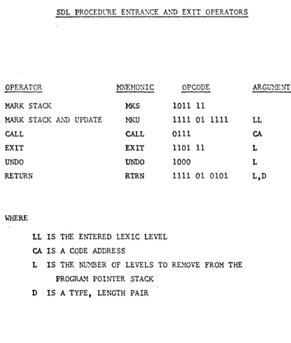
H. Procedure Entrance and Exit
. Procedure entrance and exit are a form of control statement execution, but are more complex than those statements described in IV-G, since the Control Stack and the Display may also be affected.
Procedure entrance and exit always affects the Program Pointer Stack and affect the Control Stack and Display when there is local data and/or parameters.
A call to a procedure with no local data and no parameters requires I
only the Call operator (see IV-G). A call to a procedure with local data but no parameters requires a Call operator followed by a Mark . Stack and Update operator executed inside the procedure. A procedure
with parameters and wit? or without local data requires a Mark Stack operator, followed by the operators to put the actual parameters on the Evaluation Stack, followed ~y a Call operator. Inside the procedure, a Construct Descriptor Formal operator is executed. (See Figure 10).
The Call, Mark Stack, and Mark Stack and Update operators will be described here; the Construct Descriptor Formal operator will be described in section IV-I.
Call (CALL): The argument of the Call is the code address of the pro-cedure to be entered. Execution of the Call causes the current
. .
Mark Stack (MKS): The Mark Stack operator causes construction of an entry on the top of the Control Stack. This entry contains the current values of the Name and Value Stack Pointers. The Exited
Lexi~ Level field of the entry is set to the value of the current lexic level, and the Entered Lexie Level field is set to zero. Mark Stack and Update (MKU): The Mark Stack and Update operator has
as an argument the lexi~ level of the procedure being entered. This operator causes construction of an entry on the top of the
~
Control Stack. The entry contains the current values of the Name and Value Stack Pointers. The Exited Lexie Level field of the entry is set to the value of the current lexic level, and the Entered Lexic Level field is set to the value specified as the operator argument. The Display Stack entry for the specified
lexic level is set to the current value of the Name Stack Pointer. The current lexic level is changed to the specified lexic level.
All procedure exits are done with the RETURN statement; however, the operator generated depends upon whether or not the procedure contains local data or parameters, and upon whether or not the procedure is typed.
If the procedure cont~in5 no local data and has no parameters (and therefore did not change the Control Stack upon entrance), then an Undo
I
operator is used to effect the return. If there is either local data or parameters an~ the procedure is not typed, then
used. If there is either local data or parameters
!
an Exit operator is I
I
The Undo operator was described in IV-G. The Exit operator will be
described here, and the Return operator will be described in section IV-I.
I. Param~ter Passing--Returning of Values
The formal parameter statement assigns a type (and length) to each of the formal parameters. The SDL programmer has the option of having the SDL machine (interpreter) verify that the actual parameter matches the formal. parameter. Since this check is time-comsuming, it is typically not performed once a program has been debugged. The consistency check is performed by the Construct Descriptor Formal operator (see Figure 11). When the check is to be done, this operator has, as its arguments,
"descriptor templates" for each of the formal parameters. The description of this operator follows:
Construct Descriptor Formal (CDFM): The Construct Descriptor Formal operator assumes that a Mark Stack operator was executed before the actual parameters were placed on the Evaluation Stack • . The current lexic .level is changed to the lexic level specified by
the operator. The specified lexic level is also put into the Entered Lexic Level field of the top entry in the Control Stack. The Display Stack entry for the specified lexic level is set to
the current value of the Name Stack Pointer. The current lexic
level is set to the specified lexic level. The number of descriptors specified is constructed on the Name Stack using the in-line
des-c~i~tor information plus the corresponding descriptor information
on the Evaluation Stack. The type and length fields are compared for con~~~~ency
...
between corresponding descriptors on the Evaluation and Name Stacks. The Evaluation Stack is cut back after construction.
The values returned by typed procedures in SDL should agree in type and length with the formal type of the procedure itself. The SDL programmer again,has the option of specifying whether or not this con-sistency check is performed by the interpreter. If this check is to be performed then the Return operator contains a descriptor template in-line following the operator.
Return (RTRN): The Return is the same as the Exit operator prior to popping entries off the Program Pointer Sta~k. At this point, the data descriptor on the Evaluation Stack is compared to the in-line descriptor for consistency. If the data is on the Value Stack,
J. Special Operators
In order to illustrate further the complexity and flexibility possible with a machine such as the B1700, several of the special operators will also be described.
Search Linked List
The Search Linked List operator is used principally by the HCP to allocate memory space. This operator compares a value with a list of linked structures, searching for the indicated rela~ionship or the end of the list. The argument specifies the compare type: less, less or equal, eq~al, not equal, greater or equal, greater. There are four descriptors on the Evaluation Stack. The descriptors represent:
1) Link I~dex: the relative offset in the structure)and the size) of the field which contains the address of the next structure to be examined
2) Compare Variable: the variable to be compared to the linked structure
3) Argument Index: the relative offset in the structure) and the
siz~of the field to which Compare Variable is to be compared .. , 4) Record Address: the address of the first structure to examine
"
The operator returns the address of the structure who,se compare field was in the desired relationship to the Compare Variable, or it returns an indicator that there were no structures in the desi~ed relationship.
Reinstate
user 'program. The descriptor on the top of the Evaluation Stack is assumed to describe a field in the Run Structure of the program to be reinstated. The reinstating program's M-machine state is stored in its own Run Structure (each program currently executing has a Run Structure which contains the program's execution attributes). The address of the reinstating program's Run Structure is stored in the reinstated program's Run Structure. The descriptor at the top of the Evaluation Stack is removed. The address field of this descriptor addresses the Run Structure of the program which'is then reinstated.
Next Token
The Next Token operator is used by compilers to scan source images. The first argument is the data address of a descriptor which describes the first character to be examined. It is assumed that this character is non-blank. The second argument is a "separator" character (such as "-" in COBOL). The third argument is the "numeric-to-alpha indicator".
If the character described by the fir~t argument is a special character, then the operator is exited with a descriptor on the top of the Evalu-at ion Stack which describes this character, and with the descriptor described by the first argument advanced to point to the nex~ character in the source image.
If numeric-to-alpha indicator is 1 then the stopper is set to "A";
other-.
wise, if the first character is numeric then the stopper is set to "0"; 'otherwise, the stopper is set to "A". Charac te'rs are sequentially
v.
ConclusionIn this brief description of the B1700 Software Development Language (SDL), and its underlying S-machine, I have attempted to give some indication of the flavor of SDL but, more importantly, to illustrate the extreme flexibility and suitability of the B1700 for the tasks for which it was designed: the writing of (language) interpreters and emulators. We who have used SDL feel that it is well-suited for the type of programming for which it was designed. We could not agree more
-with Saltzer et al (MIT, 1970) that one of our best decisions was to program the operating system in a higher-level language. However, the degree of success of the software depends very heavily upon the suitability of the hardware to the software and to the language in which the software is written •. The Burroughs B1700, by its very natur~, has proven to be quite suitable to the tasks to which it has been assigned. It should be pointed out, that because all of the software for the B1700 has been written in a higher-level language, all of it (including the
· VI. Acknowledgements
This paper would be incomplete without acknowledgement to the people who are responsible for the original design of the SDL language and
VII. APPENDIX I: SDL S-OPERATORS
RELATIO~AL OPERATORS
NANE M1-."EMONIC OP CODE SIZE ARGm!E~7S
EQUAL TO EQL 6
LESS THA~ LSS 10
LESS THA~ OR EQUAL TO LEQ 10
GREATER THA0: GTR 10
GREATER THA:l CiR EQUAL TO GEQ 10
NOT EQl:AL TO NEQ 6
AR:IT~fETIC OPERATORS
NA...v.E m.'EMONIC OP CODE SIZE ARGl:xEt'-t"TS
ADD ADD 6
SUBTRACT SUB 6
l-1ULTIPLY MUL 10
DIVIDE DIV 10
HODtLO MOD 10
REVERSE SL13TRACT RSUB 10
REilERSE DIVltE RDIV 10
REVERSE }!ODULO RMOD 10
NEGATE NEG 10
CO~~cRT TO DECI:L~L DEC 10
CONV'ERT TO BI~.~Y BIN 10
LOGICAL OPERATORS
NANE M}."EMONIC OP CODE SIZE ARGUMEt."TS
At.'D AND 10
OR OR 10
EXCLUSl\'E-OR XOR 10
NOT NOT 10
STRl~G OPERATORS
NA.'1E ID.'EMONIC OP CODE SIZE ARGUXE~'TS
CONC.o\TE ~ATE CAT 6
SUBSTRI~G TWO 5S2 10
SDL S-OPERATORS (CONTINUED)
LOAD OPERATORS
NA."fE m."EMONIC OP CODE SIZE ARGUNENTS
-~tAKE DESCRIPTOR MOSC 10
VALL"E DESCRIPTOR VDse 10
DESCRIPTCR DEse 6 DA
NEXT OR PREVIOUS ITEM NPIT 10 V,DA
LOAD VALL"E L 6 DA
LOAD ADDRESS LA 4 DA
ARRAY LOAD VALL"E AL 10 DA
ARRAY LOAD ADDRESS ALA 6'· DA
I!-'1)EXED LOAD VALUE IL 10 Dk
I~1)EXED LOAD ADDRESS ILA 4 DA
LOAD LITERAL LIT 4 D,LITERAL
LOAD 10-BIT LITERAL LITN 4 LITERAL
LOAD LITE~~L ZERO ZOT 4"
LOAD L ITEML O},'E ONE 4
STACK OPERATORS
NA."'!E MNEMONIC OP CODE SIZE ARGUME~lS
BUMP VALt"E STACK POI~'TER BVSP 10
DUPLICATE DUP 6
DELETE DEL 10
EXCHANGE XCH 6
FORCE VALL'E STACK FVS 6
STORE OPERATORS
NANE MNEMONIC OP CODE SIZE ARGUNE~lS
STORE DESTRUCTI\"E STOD 4
STORE NO~-D~STRUCTI\~ LEFT S~1)L 6
STORE ~O~-DESTRUCTlv"E RIGH! SNDR
10
CONSTRUCT DESCRIPTOR OPERATORS
NA."iE MNEMONIC OP CODE SIZE ARGUMENTS
-CONSTRI:CT DES. BASE ZERO CDBZ 10 D
CONSTRI:CT DES. LOCAL DATA CDLD "6 N,D1, ••• ,DN
CONSTRrCT DES. FOR:!AL CDFM
10
Lt,!SDt S-OPERATORS (CO~INUED)
LOAD OPERATORS
~ m."EMONIC OP CODE SIZE ARGUMENTS
W.J<E DESCRIPTOR MDSC 10
VALL"E DESCRIPTOR VDSC 10
DESCRIPTCR DESC 6 DA
heXT OR PREVIOUS ITEM NPIT 10 V,DA
LOAD VALCE L 6 DA
LOAD ADDRESS LA 4 DA
ARRAY LOAD VAlCE At 10 DA
ARRAY LOAD ADDRESS ALA 6- DA
1~1)EXED LOAD VALUE It 10 DA
It.'DEXED LOAD ADDRESS lLA 4 DA
LOAD L ITER .. \L LIT 4 D,LITERAL
LOAD lO-BIT LITE~~L tITN 4 LITERAL
L~~ LITE~~L ZERO ZOT
4-LOAD L ITERAL O~"E ONE 4
STACK OPERATORS
NA .. '1E MNEMONIC OP CODE SIZE ARGUMENTS B ill1P VAt L "E STACK POI!'<'TER BVSP 10
DUPLICATE DUP 6
DELETE DEL 10
EXCHANGE XCH 6
FORCE VALliE STACK FVS 6
STORE OPERATORS
NANE MNEHONIC OP CODE SIZE ARGtJMENTS
STORE DESTRUCTI\"E STOD 4
STORE NO~-D~STRUCTI\"E LEFT S!'<'DL 6
STORE NO~-DESTRUCTlv"E RIGHT St-."'DR 10
CONSTRUCT DESCRIPTOR OPERATORS
NA.."fE MNEMONIC OP CODE SIZE ARGUMENTS
-CONSTRt:CT DES. BASE ZERO CDBZ 10 D
CONSTRt:CT DES. LOCAL DATA CDLD -6 N,Dl, ••• ,DN
CONSTR[CT DES. FOR~lAL COFM 10 LL,E
SDL S-OPERATORS (CO~lI~~D)
CONSTRUCT DESCRIPTOR OPERATORS ( CO:-''TINUED)
NA!-IE Mf'..'ENONIC OP CODE SIZE ARGmlE'!'-.'TS CONSTRUCT DES. FROX PREVo CDPR 6 N,Dl, ••• ,DN CONSTRCCT DES. FRO~'l PREV. & ADD CD AD 6 . N,Dl, ••• ,DN
CONSTRUCT DES. FRO)-l PREV. &
NULTIPLY CDMP 10 N,Dl, ••• ,DN
CONSTRUCT DES. LEXIC LEVEL CDLL 10 DA,D
PROCEDGRE OPERATORS
NA}!E l-fu'EMONIC OP CODE SIZE ARGmlE~'TS
CALL CALL 4 CA
IF THEN IFTH 4 CA
IF THEN ELSE ITEL 6 TYPE, CA, CA
CASE CASE 10 N,TYPE,CA1, ••• ,CA~
Uf'.'DO Ut-."DO 4 L
Ut-.'DO CONDITIO:;ALLY UNDC 10 L
RETOR~-Vl RTRN 10 L
RETURN-V2 ItTRN. 10 L,D
EXIT EXIT 6 L
CYCLE CYCL 6 DISPLACEME};'T
MARK STACK MKS 6
MARK A~'D UPDATE MKU 10. LL
MISCELLA~cOUS OPERATORS
NA!oIE Mt>.'EHONIC OP CODE SIZE ARGUMEr-..'TS
SWAP SWAP 10
INTERRUPT STATUS lIS 10
FETCH FECH 10
DISPATCH D1SP 10
HALT HALT 10
READ CASSETTE RDCS 10
LENGTH LENG 10
LOAD SPECIAL LSP 10 V
CLEAR CLR 10
CO!-1}1ONI CA TE COM}{ 10
REINSTATE
REIN
10FETCH CXP FCMP 10
ADDRESS ,ADDR 10
SAVE STATE SVST 10
HARDWARE NONITOR HHON 10
OVERLAY OVLY 10
PROFILE PRFL 10 N
Burroughs, 1968 Burroughs, 1969a Burroughs, 1969b Burroughs, 1969c Burroughs, 1969d
Burroughs, 1971
Burroughs, 1972a
Burroughs, 1972b Cheatham, 1966
Corbato, 1969
Dijkstra, 1968
Hauck, 1968
Huffman, 1952
Lucas, 19G9
REFERENCES
Burroughs B5500 ESPOL Reference ~!anua1, 1032638
Burroughs 85500 Extended ALGOL Reference ~!anua1, 1028024 Burroughs 85500 Systems Reference Manual, 1021326
Burroughs B5700 System Reference !.~anual, 1043676 Burroughs B2500 and m500 Systems Reference 1:anual, 1025475
Burroughs B6700 Extended ALGOL Language Information Manual, 5000128
Burroughs S~~11 Syster.~ Software Development Language h~ual, (to be released)
Burroughs Bl7CO Systems Reference Hanual, 1057155
Cheatham, T. E., Jr., "The Introduction of Definitional Facili ties into Higher Level Programming languages",
Froc. FJCC, Vol. 29 (1966)
Corbato, F. J., "PL/I as a Tool for System Programining", Datamation, Vol. 15, No. 5, ~y, 1969)
Dijkstra, Edsger W.,
"00
To Statement Considered Harmful", ~, Vol. 11, No.3, (:r.!arch, 1968: Letters to the Edi tor)Hauck, E. A., and Dent, B •. A., "Burroughs" B6500/B7500 Stack 1rechanism", Proc. SJCC, Vol. 32 (1968)
Huffrnan, D. A., "A ~tethod :'C'T the Construction of Minimum Redundancy Codes", Proc. IRE, Vol. 40 (1952) Lucas, P. ,ahd Walk; K. I ttOn the Formal Description
of PL/Ift
Lyle, 1971
McKeeman, 1967
~cKeeman, 1970
MIT, 1970
Randall, 1964
Sammett, 1971
Sl1mick, 1971
Weinberg, 1971
Wilner, 1972a
Wilner, 1972b
Lyle, Don M., "A Hierarchy of High Order Languages
for Sys tems Programmingtt , Proc. AC~! SI GPIAN Symposi urn on Languages for Systems Inp1ernentation, SIGPLAN Notices, Vol. 6, No .. 9 (October, 1971)
McKeeman, W. M., "Language Directed Computer Design", Proce FJCC, Vol. 31 (1967)
McKeeman, W. M., Horning, J. J., and Wortman, D. B., A Compiler Generator, Prentice Hall, Inc., Englewood Cliffs, N. J. (1970)
Progress Report VII, Project 1,:~C, Massachusetts Institute of Technology, Canbridge, Mass., p. 6 (July 1969 to
July 1970)
Randall, B., and Russell, L. J., ALGOL 60 Implementation, Academic Press, London (1964)
Sanunetl' Jean E., "A Brief Survey of Languages Used in Systems Implementation", Proc. ACM SIGPLAN Symposium on Languages for Systems Implementation, SIGPLAN Notices, Vol. 6, No. 9 (1971)
Slimick, John, "Current Systems Implementation Languages: One User's View", Froc. A~;1 SIGPLAN Symposium on Langu-ages for Systems Implementation, SIGPLAN Notices, Vol. 6, No. 9 (1971)
Weinberg, Gerald M., The Psychology of Computer Pro-gramming, Von Nostrand Reinhold Company, New York (1971) Wilner, W. T., "Design of the B1700", Pree. FJCC, Vol. 41 (1972)
SDL MEMORY STRUCTURE
Value Stack
...
---1,---
-
-
-
-
-Name Stack
Display
Control Stack r
-Evaluation Stack
~----
-~
~---
-Program Pointer Stack
Paged Array pages and page tables
Run Structure
FIGURE 1.
~ Base Register
Program Static Memory
Program Dynamic Memory
---NA!-rE
.
. 20 0 • NSP • 0·
DISPLAY 32 • •·
STACK POI~TER
• •
·
CONTROL STACK
·4 4
0
·
0 0 ,
·
EXITED E~Tt.RE[
LL LL •
•
.
·
1 ' _
L..-f
CSP·
•·
8·
·
·
TYPE·
·
0 20.
• 0 \~SP·
• 0NAME STACK EVALUATION STACK
16 24 8 16 24
·
·
• • 0·
·
·
0·
·
·
·
·
·
\.DDR-~ ~
LGTH ~ ,,".f..x~
c~ ., .~_L ~ c~ TYPE LGTH
illTiR r:::: c:
L--?~' r·l._\ T :--~
·
·
•·
·
•
·
0, 0·
·
·
·
·
0t
NSPPROGRAM POINTER STACK
10 22
-
,·
•·
•0
·
SEG # DISPLACENE~'T
•
·
• •
•
·
YPPSP
VALUE STACK
Display
Name
Stack
Value Stack
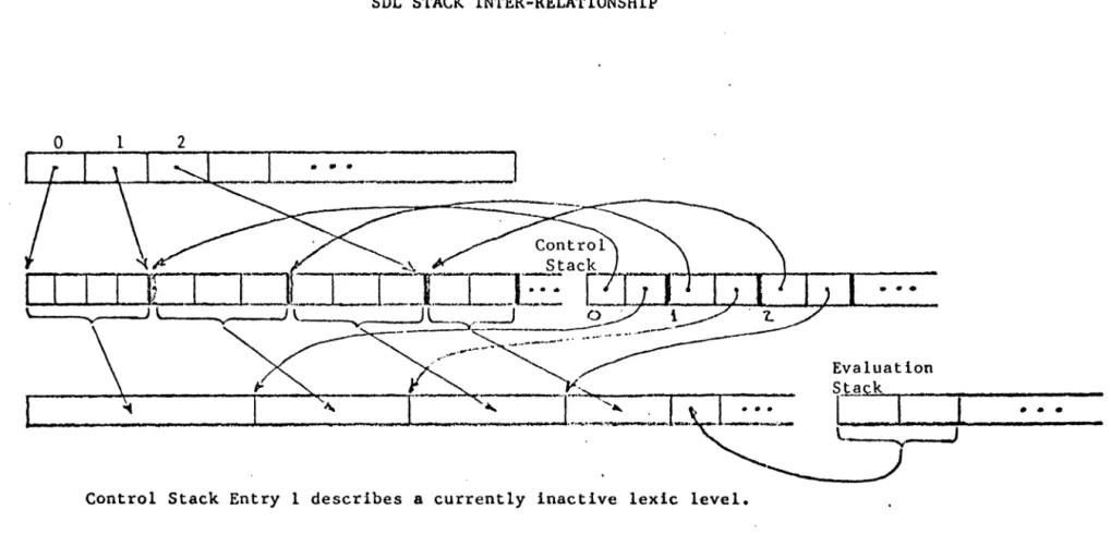
SDL STACK INTER-RELATIONSHIP
1
--·-"-· __
~
_ _
I
~-... _ _ ....,Jl ______ _ - - - - J ' - _ ... _ _ ---oJ
Control Stack Entry 1 describes a currently inactive lexic level.
FIGURE lb.
...
SDL OPCODE STRUCTURE
I
4 bitso
thru 9I
4 bits12
bi~s10 thru 14
o
thru 3[4
bitsI
6 bits15
o
thru 64FIGURE 3.
---'~---ENCODING ~·rETHOD
HUFFMAN
SDL 4,6,10
8-BIT FIELD
MCP OPERATOR ENCODING
TOTAL BITS FOR MCP'S OPCODES
172,346
184,966
301,248
UTILIZATION IMPROVE~rE~"T
437.
397.
0'7.
FIGURE 4a.
DECODING PE~ALTY
17.27.
2.67.
100%
~Eight.bit
field
90%--(j)
-
c
E
80CYo
-70%
~./'
SDL 4-6-10
E
< <Huffman enCOding""
Q)
61«Y0L-
.
~
60%_I-_---N
57%,---L----~<--~~~---~--~
50%4---~-+---+---~---~--~----~-+
1.00
1.026
1.05
1.10
Decoding time
FIGURE 4b.
SDL DESCRIPTOR FOR~~TS
SIMPLE DESCRIPTOR:
TYPE LENGTH ADDRESS OR DATA
8 16 24
ARRAY DESCRIPTOR:
TYPE LENGTH OF ELE!-lHrr ADDRESS OF FIRST ELE:[DIT PAGE SUB- LE~iGTH BETI-.'EEN
SCRIPT SIZE ELD!El\'TS ~lJNBER OF ELEHEt.;TS
8