A Peer-to-Peer Reference Architecture
Atul Singh and Mads Haahr
Distributed Systems Group Department of Computer ScienceTrinity College, Dublin Ireland
Email: [email protected], [email protected]
Abstract— Peer-to-Peer (P2P) applications are extremely popu-lar on the Internet because they allow users to share information in a decentralised manner. Internet users use file-sharing appli-cations (e.g., BitTorrent, KaZaA) to share and exchange files and collaboration applications (e.g., Jabber, Groove) to exchange chat messages and work on shared documents. Areference architecture for a domain provides an architecture template which can be used as a starting point for designing the software architecture of a system in that domain. Despite the popularity of P2P applications there is no reference architecture for the P2P domain. This paper presents a reference architecture for the P2P domain. The reference architecture has been designed to satisfy the concerns that a P2P application needs to address. The reference architecture takes a service-centric view of the P2P domain. The reference architecture can be used to describe the structure of existing P2P applications and middlewares. The paper validates the reference architecture by describing the structure of some of the existing P2P applications and middlewares using the reference architecture.
I. INTRODUCTION
P2P applications are distributed systems without any central control, where all the peers are equivalent in functionality. Recent surveys show that P2P applications generate a high percentage of traffic on the Internet [1]. The high popularity of P2P applications among Internet users is because of its ability to allow its users to share and exchange information without the need of costly and difficult to maintain centralized infrastructure. Internet users use file-sharing applications (e.g., BitTorrent [2], KaZaA [3]) to share and exchange files and collaboration applications (e.g. Jabber [4], Groove [5]) to exchange chat messages and work on shared documents. Despite the popularity of P2P applications there is no ref-erence architecture for the P2P domain. This paper presents a reference architecture for the P2P domain.
Asoftware architecturedescribes the structure of a software system. It describes and defines the software elements that comprise the system, the externally visible properties of these elements, and the relationships among them [6]. Software ar-chitectures are used to communicate the high-level design of a system to a diverse audience which may include programmers, managers and customers. The software architecture design phase is used to take design decisions which affect a system’s remaining development, deployment and maintenance life.
A reference architecture defines the software elements, their functional responsibilities and the allowed interactions between them for a particular domain [7], [6], [8]. Reference
architecture can be used as the starting point for designing the architecture of a software system of that domain. A reference architecture saves time and effort in the areas of requirement analysis and functional partitioning of the system [9]. Reference architecture is often used in mature domains like compilers and databases. For example a compiler is composed of a scanner parser, semantic analyzer and a code generator subsystem [10]. The dramatic success of Napster [11] in 1999, brought P2P applications into the limelight. Since then the research community has done a lot of work on P2P and many new P2P applications have been developed. Wikipedia [12] lists more than one hundred P2P applications. The authors feel that the P2P domain has reached a level of maturity that a reference architecture should be established for it. This paper proposes a possible reference architecture for the P2P domain.
Component-Connector UML 2.0
element element
Component Component
Connector Associations
Role Not represented
Port Port
Protocol Note
TABLE I
THEUML 2.0ELEMENTS USED TO DRAW COMPONENT-CONNECTOR
DIAGRAMS.
has given rise to P2P middlewares (e.g. JXTA [18], MSN P2P [19]). While these middlewares facilitate P2P application development, there is a lack of a common vocabulary to effectively describe the structure of these middlewares and P2P applications. The reference architecture presented in this paper can be used to describe and compare the structure of P2P applications and middlewares. This paper uses the reference architecture to describe the structure of some popular P2P applications and middlewares. The reference architecture can be used as a starting point for developing the software architecture of new P2P applications and middlewares. The reference architecture can be used to develop a customizable P2P middleware which allows instances of different types of architecture elements in the reference architecture to work together with each other to create a P2P application.
The rest of the paper is organized as follows. Section II presents the background material that is required to understand the work presented in this paper. The section defines Service Oriented Architecture (SOA) and discusses the rationale be-hind taking a service centric view. The section also presents the diagrammatic notation used to describe the reference architecture. Section III presents a summary of the study of existing P2P applications and middlewares which is used as the basis for deriving the reference architecture. Section IV presents the reference architecture. Section V validates the reference architecture by describing the structure of some of the existing P2P applications and middlewares using the reference architecture. Section VI presents the conclusion of this work.
II. BACKGROUND
A. Service-Oriented Architecture
A service is a unit of work done by a service provider to achieve desired results for a service consumer [20]. Service-oriented architectures (SOA) is an approach that utilizes soft-ware services as fundamental elements for developing softsoft-ware applications [21], [20], [22]. In SOA software resources are services available and discoverable on a network. Common Object Request Broker Architecture (CORBA), Microsoft’s Distributed Component Object Model (DCOM) and SOAP are examples of middlewares that provided this functionality.
In SOA the underlying implementation details of a service are hidden from the service consumer through encapsulation. There is a loose coupling between the service provider and
the service consumer which means that changes can be done in either one of them without affecting the other. The service consumer uses the service interface description and the service address to access the service. The service provider can easily change the implementation of the service without breaking the service consumer. Also, if required, the service consumer can use a service at an alternate location if it has same service interface as the original service provider. The loose coupling between the service provider and consumer facilitates the use of the same service across many applications, thereby reducing the development cost and errors in the application and ensuring faster development time.
The reference architecture uses the service-oriented archi-tecture because it lends itself well to modelling P2P applica-tions and middlewares. A P2P system is used to share a wide variety of resources and services. A P2P system can be used to access shared services which perform tasks like providing information about other peers on the network, numerical computations and routing of messages on the overlay network. A P2P system can be used to access a wide variety of shared resources like files, videos, messages, CPU cycles and storage space. However the shared resources can be accessed through services running on the peers. Since all the sharing in a P2P system can be conceptualized using services, a service-oriented approach has been used in the reference architecture. The reference architecture is designed to support sharing and access of services on a P2P network.
The paper uses the term servent 1 to refer to components which provide a service and can be used to access a similar service provided by another peer. A servent can act both as a client and a server. All the peers in a P2P network are equivalent in functionality and can act both as a client and a server. A peer needs to act both as a consumer (client) and provider (server) for all the concerns mentioned in Table II because of which the reference architecture handles most of these concerns using servents.
Peers join a P2P network to utilize services offered by other peers. The services can be divided into two types:
network service (NES) and node service (NOS). A network service is available on more than one peer in the network. Different instances of the network service work together to execute a task. A node service is offered by an individual peer. The service is specific to the peer offering the service. This distinction is important as it determine the way a service will be invoked.
B. Documenting Software Architecture
Software architecture is documented using views, each of which concentrates on a different aspect of the software system. Different researchers suggest using different types and numbers of views for documenting software architectures. For example [23] suggest using 4+1 views, [6] suggest using 3 views and Soni et. al. in their works [7], [24], [25] suggest us-ing 4 views. This work follows the suggestion given by Soni et.
1coined by merging together the first three letters of the word server and
al.. They suggest using four views calledcode view, execution view, module view and conceptual viewto document a software architecture. The views are enumerated in the reverse order in which they should be designed. The first three views deal with the actual implementation of the software system using programming languages, operating systems, communication mechanisms and so forth.
The fourth view or the conceptual view describes the struc-ture of the software system at a high level of abstraction using architecture elements which can not be directly implemented by using software technology [7]. In this view the functionality of the system is mapped to architecture elements called con-ceptual components (or just components), with coordination
and data exchange handled by elements called connectors.
Both components and connectors can be further decomposed into more components and connectors. The notion of build-ing a system by interconnectbuild-ing components is appealbuild-ing because of the potential for reuse and for incorporating off-the-shelf components. The components interact with the outside world using elements called ports. A port describes both the messages (operations) that the component can process and the messages that it invokes. Connectors interact with the components using elements calledroles. Both ports and roles obey protocols. A protocol is defined as a set of incoming message types, outgoing message types and the valid message exchange sequence. A port and a role can be connected together if the port’s protocol is the conjugate of the role’s protocol. Because of space constraints this paper only presents the conceptual view of the reference architecture.
The diagram used to describe a conceptual view is called a component-connector (CC) diagram. A CC diagram shows the elements (e.g. components, connectors ) of the conceptual view. The paper uses the UML 2.0 standards to draw the CC diagrams. There is no direct mapping between the elements of the component-connector diagram and the UML notation [26]. Table I shows the UML elements that have been used to draw the elements of CC diagrams. UML components can contain other UML elements which makes them an ideal choice for representing CC components. The newly introduced concept of ports in UML 2.0 is similar to the ports in CC diagrams and has been used to represent the ports. The paper uses UML associations to represent connectors as suggested in [26]. Since roles and ports which are connected to each other must obey similar protocols, roles are not documented in the CC diagrams in this paper.
III. CORE-CONCERNS FOR AP2PAPPLICATION
Current P2P applications can be divided into three major categories based on application domain: parallel computing, content-management and collaborative [27]. The authors have studied P2P middlewares and applications belonging to all the three major categories of P2P applications and have identified the concerns that a P2P application needs to address [28]. The concerns can be divided into five groups. Table II presents the groups along with the concerns. The concerns are the use-cases that a P2P application needs to address. The reference
Group Concern
Naming Identification of entities in a P2P system (identification). Resolution of entity id to a physical address (resolution). Overlay Search for a connected peer on the overlay network Management (search).
Handle join requests (join). Handle leave requests (leave).
Service Advertise services/resources to share (advertise). Management Discovery of shared services/resources (discovery).
Access the service/resources (Access). Message Maintain the topology (topology). Routing Routing of messages (routing). Security Authentication of peers (authentication).
Authorization of peers to access a resource/service (authorization).
Secure transmission of messages (confidentiality).
TABLE II
THE CORE CONCERNS THAT AP2PAPPLICATION NEEDS TO ADDRESS.
architecture presented in this paper handles all these use-cases. P2P systems assign a network (underlying physical network) and location independent id (identification) to the entities (e.g., peers, resources, services, etc.) in a system. The id’s allow P2P systems to manage entities whose physical location (IP address) on the network changes with time. The id’s are dynamically resolved (resolution) to determine the current physical location of the entity. For example, in the JXTA [18] reference implementation the id is a 128 bit universally unique identifier (UUID) generated by the peer. The JXTA reference implementation uses a combination of a central server (called rendezvous server) and IP multicast to resolve the id to a physical address.
Peers join an overlay network through another peer which is already connected to the overlay network. Connected peers’ addresses may be well known information or they can be obtained by IP multicast (search). The peer accepting the con-nection (join) may redirect the incoming peer to another peer. The connecting peer may also be supplied with information relevant for it. For example, in Jabber [29], [4], [30] peers connect to a well known server to join the overlay network. The server provides the connecting peer with information about the availability of other peers on the network.
Peers use the overlay network to advertise their resources
and services and to discover new resources and services
which they can access. For example, in Jabber the peers
advertise the details of the shared resources and services to a central server. Peers can discover the details about the shared services/resources by sending a query message to the central server. The service/resources can be accessed by doing a remote process call (RPC). Peers may inform one or more peers on the overlay network when they leave the overlay network. For example, in Jabber the peers send a presence message of type unavailable to the central server.
Fig. 1. A UML diagram providing a high level overview of the P2P reference architecture.
Fig. 2. A UML diagram presenting a conceptual view of the runtime component.
destination peer’s address is available. If the destination peer is not accessible or its physical address is not available then the source peer mayroutethe message to one or more known peers on the network, which can in turn route the message to the destination peer. The P2P software is responsible for maintaining connections (topology) which improve the efficiency of the P2P system. Authentication, authorization
and secure transmission of messages (confidentiality) are the security-related concerns.
IV. P2P REFERENCEARCHITECTURE
[image:4.612.48.303.75.274.2]Figure 1 presents a high-level overview of the reference architecture. The reference architecture consists of three key components: common runtime, security and core servents. The common runtime provides the messaging infrastructure used to exchange messages between peers in order to invoke
Fig. 3. A UML diagram depicting the conceptual view of the core servents of the reference architecture. The core servents handle most of the concerns which need to be addressed by a P2P application.
(access) a service. The common runtime is used by all types of servents to communicate with servents on other peers. The security component deals with handling the security related concerns such as authentication, authorization and the secure transmission of messages. The reference architecture suggests using aspects [31], [32] to implement the security-related con-cerns. This paper does not define the structure of the security components. Except for routing, the core servents address all the concerns that a P2P application needs to handle. The routing logic may vary for different services and is handled by the servent for which a request arrives. In the reference architecture a P2P application consists of application servents (e.g., for file sharing or instant messaging) that are responsible for the application logic. The reference architecture supports multiple co-existing application servents. This means that an application developed using the reference architecture can be used to share multiple services. An instance of the reference architecture can have multiple instances of the core servents, security component and runtime. These instances can be used by an application to connect to different overlay networks.
There are six core servents (see Table IV) which handle all the concerns except routing and access. Figure 3 shows a conceptual view of the core servents. The core servents along with the concerns they handle are shown in Table IV. A servent can handle incoming messages from both remote and local servents and applications. The protocol used by the core servent ports is shown in Table III. The protocols are documented using the notation suggested in [7]. The table does not show implementation-specific details (e.g. source IP and port of message that are sent with the messages). The protocols define the structure of the messages exchanged to invoke these servents. The OverlayNetworkDiscovery (OND) servent is used to search for connected peers on the overlay network to which a new peer can connect. The port portOND of the OND servent expects a single incoming message
getPeers with the new peer’s information and responds with information about a list of peers to which the new peer can connect. The MembershipManagement (MM) servent is used to handle requests to join and leave the overlay network. The port portMMJ of the MM servent expects an incoming messagejoinOverlayNetworkwith the new peer’s information.
[image:4.612.48.304.319.481.2]portMMJProtocol portONDProtocol portSDProtocol
incoming incoming incoming
joinOverlayNetwork( getPeers( findService(name, newPeerInformation) newPeerInformation) criteria)
outgoing outgoing outgoing
redirect(PeerInformation[]) PeerInformation[] ServiceDetail[] reject
accept(PeerInformation[])
portSAProtocol portGetIdProtocol portGetPeerProtocol
incoming incoming incoming
advertise(ServiceDetail) getId( getPeer(id) ServiceOrResource
Description)
outgoing outgoing outgoing
success id PeerInformation
fail
portMMLProtocol portTAProtocol
incoming incoming
leaveOverlayNetwork registerServentCache( serventCacheName, topologyAdaptationPolicy) outgoing outgoing
accept reject
TABLE III
THE PROTOCOL OBEYED BY THE PORTS OF THE CORE-SERVENTS IN THE
REFERENCE ARCHITECTURE.
can reject, accept or redirect the new peer’s request. The port portMML of the MM servent is used to leave the overlay network and it expects a single incoming message called leaveOverlayNetwork. A peer wishing to advertise its
services sends an advertise message to the port portSA of
its ServiceAdvertisement (SA) servent. The SA servent may advertise the service detail to the SA servent of the other peers on the overlay network and responds back to its peer with a
successorfailmessage. The ServiceDiscovery (SD) servent is used to discover the details of services on the overlay network that match a search criterion. The portSD port of the SD
servent expects a single incoming message findService with
the search criteria and responds with the details of a list of services matching the search criteria. The Naming (N) servent is used to assign a unique identifier to entities in a P2P system (using portGetID) and to resolve an entity’s id to a physical IP address (using portGetPeer).
An overlay network can be defined in terms of the poli-cies it uses to implement the different components of the reference architecture. A peer can join an overlay network if it has the set of instances of the reference architecture elements that implement the policies that the overlay network desires. Existing P2P systems like JXTA [33] try to make P2P applications interoperable by defining standards (format and on wire form of the message) for the messages exchanged between peers. However messaging standards alone do not ensure interoperability. For example, a peer (P) might not implement the SA servent and instead use a multicast on the overlay network policy for the SD servent to discover services on the overlay network. An overlay network (ON) with a small
Core Servent Concern
OverlayNetworkDiscovery (OND) Search
MembershipManagement (MM) Join (JN), Leave (LV) ServiceAdvertisement (SA) Advertise
ServiceDiscovery (SD) Discovery
Naming (N) Identification (ID), Resolution (RES) TopologyAdapter (TA) Topology
TABLE IV
THE CORE SERVENTS OF THE REFERENCE ARCHITECTURE AND THE
CONCERNS THEY HANDLE. THE ACCESS CONCERN IS HANDLED BY THE CLIENT AND SERVER COMPONENTS OF THE COMMON RUNTIME. THE
ROUTING CONCERN IS HANDLED BY THE INDIVIDUAL SERVENTS.
portCreateProtocol portAddProtocol portSearchProtocol
incoming incoming incoming
createServentCache( addServentCacheEntry( searchServentCache( serventCacheName, serventCacheName, criteria) setOrKeyValuePair, serventCacheEntry)
topologyAdaptation-Policy)
outgoing outgoing outgoing
ServentCache success serventCacheEntry[] fail
portDeleteProtocol portClientProtocol portServerProtocol
incoming incoming incoming
deleteServentCacheEntry( sendMessage( receiveMessage(
criteria) dstnAddress, Message)
Message)
outgoing outgoing outgoing
success success
fail fail
TABLE V
THE PROTOCOL OBEYED BY THE PORTS OF THE RUNTIME COMPONENTS.
number of peers might expect its peers to use multicast to all known peers policy for the SA servent and to use the information provided by the SA servent to perform service discovery (SD). When P joins ON, messaging standards for example those set by JXTA, ensure that peers on ON can understand the SD messages send by P. However the peers on ON will not know how to process the messages sent by peer P.
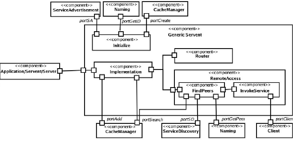
Fig. 4. A UML diagram of the conceptual view of a generic servent. All the connectors depict local method invocation. The Routing component may use the Client component.
data stored in a servent cache will vary with the service. For example, for a file sharing service the servent cache can be a set of (file id, host) pairs. One servent cache can be shared across multiple servents.
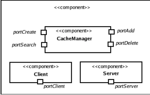
Table V shows the protocols used by the ports of the common runtime components. The port portCreate of the CacheManager component is used to create a servent cache. In the incoming message, the port expects a name for the servent-cache, the topology adaptation step to be used on the servent cache and the description of the servent cache (set or table of (key, value) pairs). The port creates a new servent cache if one with the given name and properties does not exists and returns a reference to it. The portAdd, portDelete and portSearch ports of the CacheManager are used to add, remove and search entries from a servent cache with a given name. The portClient port of the Client component is used to send a given Message to a destination address. The Message format is determined by the protocols obeyed by the port to which the message is destined. The portServer of the Server component is used to receive messages. The server directs an incoming messages to an instance of the servent type (specified in destination Address) for which the message is intended.
The TopologyAdapter servent works on the servent cache. It will normally be used to change the servent cache entries so that a service request can be processed more efficiently. A servent cache would generally contain information about other peers on the overlay network which provide a similar service. A request for a service would be redirected to one or more of these peers if the local servent handling the request can not handle it. The TopologyAdapter servent ensures that the servent cache contains entries which will help in an optimal
processing of the service.
Figure 4 shows the conceptual view of a generic P2P servent. During initialization, a servent may do either of the following: i) advertise its services using the port portSA of the ServiceAdvertisement servent and/or ii) use the port portGetId of the naming servent to get an id for the servent, and iii) use the port portAdd of the CacheManager to create a servent cache. The Implementation component provides the actual service implementation. The Implementation component uses the CacheManager to find an existing response for an incoming request from a servent cache (if used by the servent). If a response is available from the CacheManager then it is returned. However if a cached response is not available then the Implementation component tries to process the request locally and send a response. If it can not process the request locally then it uses the RemoteAccess component that uses other peers on the overlay network to process the request and generate a response. The Implementation component directs a request to the Router component for processing if the request’s destination is not the servent’s peer. Before returning the response the Implementation component updates the servent-cache (if used by the servent) using the CacheManager.
its IP address. The InvokeService component then processes the incoming request using the servents on the peers supplied by the FindPeer component.
V. APPLYING THEREFERENCEARCHITECTURE.
All the components of the reference architecture are ab-stractions that can have multiple instances implemented using different policies. This section describes some of the exist-ing P2P applications and middlewares usexist-ing the reference architecture. This section describes: Gnutella a pure P2P file-sharing system, Freenet a P2P content storage system, JXTA a multi-purpose P2P middleware and Jabber a platform for P2P collaboration. For each P2P system the routing algorithm and the servent cache structure is described. The routing policy and the servent cache used by all the servents in the P2P system is documented using tables.
A. Gnutella
Gnutella [34], [35] is a decentralized P2P file-sharing net-work. Gnutella creates an unstructured, self-organizing overlay network of peers. There is no constraint on the position of the files. A peer uses a breadth-first search on the overlay network to locate a file. Once the peer containing the file is located, a direct connection is used to transfer the file.
All the peers in Gnutella implement two application servent which are: File getFile(String fileName) which is used by other peers to download files and PeerInformation getPeers() which is a network service used by a connected peer to discover other peers on the overlay network. Table VI shows the policies used by Gnutella to implement the different core-servents. The table also describes the routing policy and the servent cache used by the different servents. New peers join the Gnutella network using an available peer from a list of well-known peers which are connected to the Gnutella overlay network. When the new peer joins the network the peer accepting the connection provides the new peer with information about other peers on the network. Naming service is provided by the Gnutella application. The application generates a unique 16 byte identifier for each new messages.
ServiceDiscovery is implemented as a network service. The ServiceDiscovery, OverlayNetworkDiscovery and getPeers() servents share a single servent-cache which is a set of ad-dresses of the peers on the overlay network. A peer searches for a file it wants by using the ServiceDiscovery servent. The ServiceDiscovery servent sends out a multicast message containing a search request for a getFile service which can provide a file matching the peer’s requirements to all the peers in the servent-cache. A peer receiving the request responds back with its address and a list of files matching the search query. If the time to live for the request has not elapsed then the peer forwards the request to all the nodes in its servent-cache. The getPeer() network service is accessed by sending a multicast to all the peers in the servent-cache. The peer receiving the request responds back with information about itself. If the request has not reached its time to live then the peer propagates the request to the peers in its servent-cache.
Servent Cache
Name Description
PeerCache (GPC) Set of Peer Information
Routing Policy Name:Multicast (GMC)
Algorithm:
if (isRequest(message)){ if (!hasSeen(message.id)){
message.TTL (Time to live) = message.TTL - 1
message.TTL! =0 ? forwardMessage(GPC - message.peer): sendMessageResponse(message.peer)
cache(message.id and message.peer mapping) }
}else{
if (hasSeen(message.id)){
forwardMessage(findPeerWhichSendRequest(message.id)) }
}
Application Servents
Name Routing Servent
Policy Cache PeerInformation getPeers() GMC GPC File getFile(String fileName) none none
Core Servents
Name Policy Routing Servent
Policy Cache OND Well-known peers none GPC MM(Join) Peers on the none GPC
overlay network
MM(Leave) none none none
SA none none none
SD Multicast to peers GMC GPC in PeerCache
N(ID) none none none
N(RES) none none none
TA none none none
TABLE VI
DESCRIBINGGNUTELLAUSING THEREFERENCEARCHITECTURE.
B. Freenet
Freenet [36], [37] is a censorship free P2P content storage and retrieval system. It provides complete anonymity to the contents publisher and user. It reduces the slashdot effect2, by caching the data on multiple nodes closer (in terms of node hops) to the contents users. All data stored on Freenet is associated with a key.
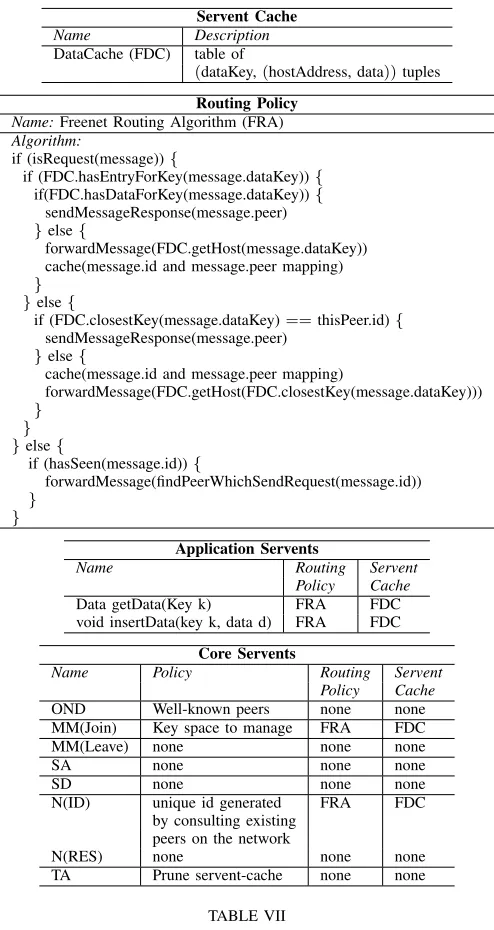
All the peers in Freenet implement two application servents which provide network services. They are Data getData(Key k) which returns data for a given key, and void insertData(key, data) which is used to publish data associated with a key. Table VII shows the policies used by Freenet to implement the core servents of the Reference Architecture. The table also describes the routing policy and the servent cache used by the different servents. New peers join the Freenet network using an available peer from a list of well-known peers which are connected to the Freenet overlay network. When a new peer joins the network the existing peers work together to assign
2Slashdot effect refers to the slowing down or temporarily closing of a
Servent Cache
Name Description
DataCache (FDC) table of
(dataKey,(hostAddress, data))tuples
Routing Policy Name:Freenet Routing Algorithm (FRA) Algorithm:
if (isRequest(message)){
if (FDC.hasEntryForKey(message.dataKey)){ if(FDC.hasDataForKey(message.dataKey)){
sendMessageResponse(message.peer) }else{
forwardMessage(FDC.getHost(message.dataKey)) cache(message.id and message.peer mapping) }
}else{
if (FDC.closestKey(message.dataKey)==thisPeer.id){ sendMessageResponse(message.peer)
}else{
cache(message.id and message.peer mapping)
forwardMessage(FDC.getHost(FDC.closestKey(message.dataKey))) }
} }else{
if (hasSeen(message.id)){
forwardMessage(findPeerWhichSendRequest(message.id)) }
}
Application Servents
Name Routing Servent
Policy Cache Data getData(Key k) FRA FDC void insertData(key k, data d) FRA FDC
Core Servents
Name Policy Routing Servent
Policy Cache OND Well-known peers none none MM(Join) Key space to manage FRA FDC
MM(Leave) none none none
SA none none none
SD none none none
N(ID) unique id generated FRA FDC by consulting existing
peers on the network
N(RES) none none none
TA Prune servent-cache none none
TABLE VII
DESCRIBINGFREENETUSING THEREFERENCEARCHITECTURE.
the new node a key space to manage. The Naming servent generates a unique key for files to be stored on freenet using SHA-1 secure hashes. The SHA-1 secure hashes ensure that same key is generated for identical files. Freenet does not allow the resolution of the id to an actual physical address to ensure anonymity of the peer storing the file.
getData(...) and insertData(...) servents share a single servent-cache which is a table of (dataKey, (hostAddress, data)) tuples. The servent cache is pruned by TopologyMan-ager to ensure that its size does not exceed a specified limit. A least recently used algorithm is used to remove the data for a key. The host address is still cached so that the data can be retrieved at a later time if required.
The getData(...) and insertData(...) servent implementations
JXTA Protocol Reference Architecture Elements
PDP ServiceDiscovery, ServiceAdvertisement PRP Client, Server
RVP Application Servents ERP Application Servents PIP Application Servents
TABLE VIII
AMAPPING BETWEEN THEJXTAPROTOCOLS AND THE REFERENCE
ARCHITECTURE ELEMENTS.
propagate a request to the host (in servent-cache) whose key is closest to the key in the request. The getData(...) request is not propagated further and a response is sent back if the key in the request is already present in the servent-cache along with the data, otherwise the request is forwarded to the host in the servent-cache whose key is closest to the key in the request. The getData(...) response is sent back to the peer which forwarded the request which in turn sends the response back to the peer from which it received the request. The response is not directly sent back to the peer from which the request originates in order to preserve anonymity of the peer interested in the resource. The insertData(...) request is not propagated further and data is added to the servent-cache if the id of the peer is closest to the key in the request than any other key already present in the servent-cache, otherwise the request is forwarded to the host in the servent-cache whose key is closest to the key in the request.
C. JXTA
JXTA [38], [18] was conceived by Sun Microsystems Inc and has been developed as an open source project. JXTA is a specification for developing P2P applications. The specifica-tions can be implemented as a framework which can be used for P2P application development. The Project JXTA reference implementation [39] is one such framework. JXTA provides components which can be used by a P2P application. For example, JXTA provides an abstraction called pipes that is similar to BSD socket interface and can be used for communi-cation between peers. JXTA defines the structure of elements like PeerInformation (peer advertisement) and ServiceDetail (service advertisement) shown in Table III. However JXTA does not provides the software architecture of a P2P system.
[image:8.612.51.298.50.515.2]peers. A peer can advertise and discover resources and services on the overlay network using Peer Discovery Protocol (PDP). The ServiceDiscovery and ServiceAdvertisement elements can exchange messages using the format specified in PDP protocol. There is no direct mapping possible between the next three protocols and the reference architecture elements. These JXTA protocols can be used by application servents in the reference architecture. The Peer Information protocol (PIP) in JXTA, can be used to inquire the status of a peer. In the reference architecture an application servent which provides the status of a peer can use this protocol. In JXTA the client may use Rendezvous Protocol (RVP) to find peers if the message has to be propagated over the overlay network. The reference architecture does not provides a dedicated servent to find peers that can propagate a message on the overlay network. This has been done to keep the list of core servents minimal. In the reference architecture a servent can use the servent-cache or the ServiceDiscovery servent to find peers which can propagate a message over the overlay network. If a direct connection to a destination peer cannot be found then Endpoint Routing Protocol (ERP) is used to find intermediate hosts which can route the information to the destination peer. In the reference architecture routing is the responsibility of the servent handling the message. The reference architecture does not stipulate a specific service that is responsible for finding peers which can be used to route messages and suggests using the ServiceDiscovery component to find peers which can route the message. If the application requires a specific service that can be used to find peers which can be used to propagate messages on the network or find peers which can route a message, then the service has to be implemented as an application servent.
D. Jabber
Jabber [29], [4], [30] provides specifications for developing instant messaging (IM) applications. Jabber implementations provide a realization of these specifications. Jabber is intended for IM applications, but the infrastructure provided by it can be used for developing other types of P2P applications.
Table IX shows the application servents that Jabber pro-vides and describes how Jabber implements the core servents. Jabber uses a hybrid P2P architecture. The Jabber server is used for authenticating peers and resolving id to a physical network address. However, peers can exchange data directly by establishing a connection which is brokered using Jabber servers. A new peer connects to the central server to join the overlay network. The peers inform the central server when they leave the overlay network. The central server provides the connecting peer with information (e.g., availability of peer and peer address) about other peers in which the connecting peer is interested. The Jabber server provides three presence related services: subscribeToPresenceInformation(...) which can be used to tell the Jabber server about interest in a peer’s (with id peerId) availability information, getSubscribedPeers() gives a list of all the peers in which the peer invoking this service is interested and getPresenceInformation(...) can be used to
Application Servents
void receiveMessage(String mesg)
boolean subscribeToPresenceInformation(String peerId) String[] getSubscribedPeers()
boolean getPresenceInformation(String peerId)
Core Servents
Name Policy OND central server MM(Join) online peers MM(Leave) central server
SA none
SD none
N(ID) central server N(ID) central server
TA none
TABLE IX
THE APPLICATION SERVENTS PROVIDED BYJABBER AND THE POLICIES
USED BYJABBER TO IMPLEMENT THE DIFFERENT CORE SERVENTS. THE SERVENTS INJABBER DO NOT USE A SERVENT CACHE. THE SERVENT
IMPLEMENTATIONS INJABBER DO NOT HAVE ROUTING CAPABILITY.
receive presence information about a peer (with id peerId) on the network. All the peers implement a service called receiveMessage(...) which can be used to send a chat message to them.
VI. FUTUREWORK ANDCONCLUSION
The paper presents a taxonomy of core concerns that a P2P application needs to address. Despite the popularity of P2P applications there is no reference architecture for the P2P domain. The paper presented a reference architecture for the P2P domain. The reference architecture uses a service-oriented approach that facilitates the development of a software im-plementation (e.g. a P2P file-sharing application) using the reference architecture because the software implementation can use the support for service-oriented architecture provided by the existing middlewares. The paper validates the reference architecture by describing four prominent P2P applications and middlewares using the reference architecture. The authors are currently working on implementing a customizable middle-ware based on the reference architecture that allows control over the core servents policies. Future work could involve developing a catalogue of policies for the core servents.
ACKNOWLEDGMENT
The work described in this article is funded by the Irish Research Council for Science, Engineering and Technology (IRCSET) under the Basic Research Grants Scheme.
REFERENCES
[1] S. Saroiu, K. Gummadi, R. Dunn, S. Gribble, and H. Levy, “An analysis of internet content delivery systems,” inProc. of the Fifth Symposium on Operating Systems Design and Implementation (OSDI), 2002. [2] [Online]. Available: http://www.bittorrent.com
[3] “Kaza,” http://www.kazaa.com/us/index.htm.
[4] D. Adams, Programming Jabber, C. Toporek, Ed. O’Reilly and Associates, 2002.
[6] P. C. Len Bass and R. Kazman, Software Architecture In Practise. Addison Wesley, 2000.
[7] R. N. Christine Hofmeister and D. Soni,Applied Software Architecture. Addison-Wesley, 2000.
[8] B. P. Gallagher, “Using the architecture tradeoff analysis method to evaluate a reference architecture: A case study,” CMU/SEI, Tech. Rep., 2000.
[9] R. Kazman, L. J. Bass, M. Webb, and G. D. Abowd, “SAAM: A method for analyzing the properties of software architectures,” inInternational Conference on Software Engineering, 1994.
[10] A. E. Hassan and R. C. Holt, “A reference architecture for web servers,” in Seventh Working Conference on Reverse Engineering (WCRE’00), 2000.
[11] “Napster,” http://www.napster.com, 1999 version, 1999. [12] [Online]. Available: http://en.wikipedia.org/wiki/Peer-to-peer
[13] M. Henning and S. Vinoski,Advanced CORBA Programming with C++. Addison Wesley, 1999.
[14] [Online]. Available: http://www.w3.org/TR/soap/
[15] P. A. Bernstein, “Middleware: A model for distributed system services,” Communications of the ACM, no. 39(2), pp. 86–98, 1996.
[16] A. Singhai, “Quarterware: A middleware toolkit of software risc com-ponents,” Ph.D. dissertation, Dept. of Computer Science, University of Illinois, 1999.
[17] W. Grosso,JAVA RMI. O’Reilly, 2001.
[18] B. T. Scott Oaks and L. Gong, JXTA In a Nutshell. O’Reilly and Associates Inc., 2002.
[19] Microsoft, “Introduction to windows peer-to-peer networking,” Mi-crosoft Corporation, Tech. Rep., 2003.
[20] H. He, “What is service-oriented architecture?” xml.oreilly.com. [21] M. S. Pallos, “Service-oriented architecture: A primer,” eAI Journal,
2001.
[22] M. P. Papazoglou and D. Georgakopoulos, “Service-oriented comput-ing,”Communications of the ACM, October 2003.
[23] J. R. Grady Booch and I. Jacobson, The Unified Modeling Language User Guide. Addison-Wesley Pub Co, 1998.
[24] D. Soni, R. L. Nord, and C. Hofmeister, “Software architecture in indus-trial applications,” inProceedings of the 17th international conference on Software engineering, 1995.
[25] C. Hofmeister, R. Nord, and D. Soni, “Describing software architecture with uml.” in Proceedings of the First Working IFIP Conference on Software Architecture, 1999.
[26] J. Ivers, P. Clements, D. Garlan, R. Nord, B. Schmerl, and J. R. O. Silva, “Documenting component and connector views with uml 2.0,” Carnegie Mellon Software Engineering Institute, Tech. Rep., 2004.
[27] D. S. e. a. Milojicic, “Peer-to-peer computing,” HP Labs, Tech. Rep., 2002.
[28] A. Singh and M. Haahr, “A survey of p2p middlewares,” submitted to EURO-PAR 2005.
[29] “What is jabber?” http://www.jabber.org/about/overview.php.
[30] C. Dodson, “Jabber technical white paper,” http://xml.coverpages.org/, Aug 2000.
[31] R. Laddad,AspectJ In Action. Manning Publications Co., 2003. [32] [Online]. Available: http://www.eclipse.org/aspectj/doc/progguide/index.html [33] “Making p2p interoperable: The jxta story,”
http://www-106.ibm.com/developerworks.
[34] [Online]. Available: http://www.gnutella.com/
[35] M. Ripeanu, “Peer-to-peer architecture case study: Gnutella network,” in First International Conference on Peer-to-Peer Computing (P2P2001), 2001.
[36] I. Clarke, S. G. Miller, T. W. Hong, O. Sandberg, and B. Wiley, “Pro-tecting free expression online with freenet,”IEEE Internet Computing, 2002.
[37] [Online]. Available: http://freenetproject.org/
[38] “Jxta v2.0 protocols specification,” http://spec.jxta.org/nonav/v1.0/docbook/JXTAProtocols.html.