Modelling Event Systems for AmI Applications Using
an Aspect Middleware Platform
1Lidia Fuentes1, Daniel Jimenez1, and René Meier2
1 Dpto de Lenguajes y Ciencias de la computación. Blvard Louis Pasteur 35,
29071 Malaga, Spain
2 Distributed Systems Group, Department of Computer Science,
Trinity College Dublin, Ireland {lff, priego}@lcc.uma.es, [email protected]
Abstract. The development of a communication service is one of the most
difficult and important challenges when developing Ambient Intelligence (AmI) applications. Since AmI applications must be able to react to external events, event-based communication is a natural way to disseminate such events amongst all interested AmI components. A wide range of diverse event systems have been developed for addressing the problems on specific domains. Although AmI applications may benefit from the features of many of these event systems, middleware platforms for AmI applications typically support just one event system. Interconnecting different event systems in a multilateral inter-working federation will provide a homogeneous interface to access the specific services and features offered by each event system. This work presents an integration example of heterogeneous event systems in a homogeneous way through the use of an Aspect Oriented Middleware platform.
Keywords: AO Middleware, Aspects, Federated Event Systems.
1 Introduction
Ambient Intelligence applications (or AmI) are distributed and loosely coupled in nature which makes it difficult to develop effective communication mechanisms for them. The ISTAG [1] has identified the ubiquitous communication feature as one of the main properties of AmI applications. This means that every device should be able to communicate with others in the environment using one or more communication mechanisms. In particular, portable devices inside an AmI environment often react based on events (e.g. lighting devices wait to receive an event that notifies of the presence of a person in a room), therefore the event-based communication mechanism seems to be the most natural way to distribute these events amongst all AmI components that must be notified about them.
1 This work is partially financed by IST-2-004349-NOE AOSD-Europe and the Spanish
Several event systems exist and some of them have been successfully used to implement ubiquitous computing applications. Each one of these event systems provides solutions to specific domains and problems. For example, Siena [2] is used for wide area event communication. STEAM [3] was developed for facilitate the communication of vehicles in proximity and includes soft real time guaranties. CNS [4] is able to add multiple features to the event system such as QoS, event filtering, security or alternative event transmission modes (push and pull). Although AmI applications could benefits from many of them, most middleware platforms for AmI normally only consider the use of just one event system. By defining a federated event system (or FES) providing a single access point to services offered by different event systems, AmI applications can choose a specific event service to adapt to very different situations.
However, to develop a FES system providing a homogeneous interface is not a trivial task. The first challenge is that it is not always possible to perform a perfect event adaptation from one system to another due to the differences in event models. The second challenge is to provide a mechanism capable of handling the evolution of event systems over time. This evolution can be caused due both to technological and to application requirement changes. This means that the FES must support the addition of new event systems or the modification of existing ones. Finally, the last challenge comes from the dynamic nature of the event system. An event system must be able to react to new events at runtime, thus it is also necessary to provide a mechanism capable of reacting to event types not considered by the event system.
Based on our previous experiences refactoring applications using the Aspect Oriented Software Development (or AOSD) technology [5], we have developed an AO middleware Platform, called AOPAmI (Aspect Oriented Platform for AmI) [6]). This paper shows how the AOPAmI platform can be effectively applied to solve the problems previously presented and to develop flexible FES applications.
The rest of this paper is structured as follows. In section 2 we discuss the benefits and problems of using the FES and the benefits derived from introducing aspects. Section 3 presents an overview of the AOPAmI platform. Section 4 presents and example modelling the FES using AOPAmI. Finally, the last section contains our conclusions and future work.
2 Towards a Federated Event System
2.1 The Motivating Example
Throughout this paper, we will show the design of a traffic monitoring (TM) application. This application detects when vehicles in a certain locality are circulating at an inappropriate speed. When this fact is detected, the application sends a warning to the driver, represented in the system by a Vehicle application, to correct his behaviour. If the undesiderable behaviour persists, after a prudential time the vehicle identification is registered and the driver will be fined by the monitoring application.
The problem here is that we can not force every car vendor to use the same event system to send the required data. So, a FES would provide an elegant solution to the heterogeneity problem associated with the use of different event systems for the application developer and it does not force vendors to adopt a pre-arranged event system.
Another problem that can be solved using a FES is system scalability. Let us consider that the TM application has a limited capability of processing events. A possible approach to solving this problem is to provide support for content filtering on each event system. This is not always possible however because not all event systems support event filtering. Additionally, if we allow an event filtering service in the Vehicle application, the user could manipulate it to avoid paying a fine. The solution is to implement this filter service in the FES application and in this way to determine which events will be finally processed by the application.
2.2 Related Work
Several authors such as [7] and [8] have proven that it is possible to build federations of event systems. But the solutions proposed by them present a series of flaws that make them not entirely appropriate for implementing the proposed example.
Table 1. FES comparative table.
Feature\Event System CNStoJMS bridge FES AOPAmI
Supported Event systems 2 N N
Event type support All CNS and JMS events Subset of events Any event
Adding of new Event systems No Yes (Limited) Yes
Runtime reconfiguration N/A No Yes
− It must provide an event translation mechanism between systems. This mechanism must translate events from and to the event model of any target event system in the federation. But it is not always possible to provide a perfect adaptation from an event system to another as was shown in [9].
− A FES should have the capacity to integrate new event systems transparently and that these event systems do not notice that they are part of a federation.
− FES services should be applied to any event system in the federation using the FES event model. Imagine the benefits of providing a set of services for an event system that originally did not support them. For example we could use STEAM for communicating vehicles but add the filter and security services (from CNS) without modifying the original event system or even define a FES service that can be used by all the federated event systems.
<DeviceProfile id="PDAProfile">
<property type="STRING" value="Java" name="target_lang"/> <property type="STRING" value="J2ME" name="version_lang"/> <property type="NUMERIC" value="2048" name="mainmemory"/> <property type="NUMERIC" value="128000" name="storagememory"/> <property type="STRING" value="ion-litium" name="batteryType"/> <property type="NUMERIC" value="8" name="batteryAutonomy"/> <property type="BOOLEAN" value="false" name=" batteryControl "/>
... </DeviceProfile> Base Elements Repository <platformArchitecture> <baseElements>
<baseElement role="Communication"> <providedInterface>
<interface name="providedInt"> <message name="recv">...</arg></message>
<message name="send">...<arg name="to" type="Object"></arg></message> </interface>
</providedInterface> ...
<impls selected="default"><impl id="default" mainclass="Communication1"/></impls> </baseElement>
<baseElement role ="Location">...</baseElement> <baseElement role ="batteryManager">
<guard><comparation property="batteryControl" operation="=" value="true"/></guard> ...</baseElement>
... </baseElements> <properties>
<property name="deviceID" type="String" value="Vehicle"/> <property name="locationData" type="Object[]"/> ... </properties>
<compositionRules> <bind-pointcut>
<from><baseElementRef role="Communication"/></from> <method-pointcut name=”send(.., null)”/> <advice-aspect type=”BEFORE_SEND”>
<concurrent><baseElement role=”Location” method=”updateLocation”></concurrent> </advice-aspect>
</bind-pointcut> ... </compositionRules>
<applicationArchitecture>...</applicationArchitecture> <instanciateBaseElements>
<instanciateBaseElement role="batteryManager">
<guard><comparation property="batteryControl" operation="=" value="true"/></guard> </instanciateBaseElement>
<instanciateBaseElement role="Location"/> <instanciateBaseElement role="Communication"/> ...</instanciateBaseElements>
</platformArchitecture>
AOPAmI Microkernel
Platform Loader
Base Element Factory
Device Profile Manager
AOPAmI-DSL Manager Base Element Container
[image:4.595.127.471.305.520.2]Location Coordination Adaptation Persistence Communication ... b a c
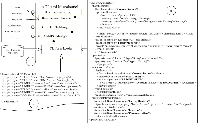
Fig. 1. AOPAmI Platform Architecture.
3 The AOPAmI Middleware Platform
to decouple platform baseElements the platform architecture is specified separately in a domain specific language (AOPAmI-DSL) based on XML (see Fig. 1 (a)). In this section we will show an overview of this language and the microkernel, which manages the base elements of the platform.
3.1. The AOPAmI-DSL Language
The AOPAmI-DSL schema, shown on Fig. 1 (a), has five main parts. The first one (baseElements tag) contains a description of the provided and required interface of the base elements used by the platform. Notice that each base element is identified by a role name. This is an architectural name that will be used to identify components instead of using an implementation interface or class name. Doing this the platform can replace any base element by other versions which provide equivalent functionality when needed, even at runtime. Secondly, the properties tag is used to define data that has to be shared by any base element in the platform. Properties are used to solve data dependencies between baseElements in an elegant and simple way (e.g. the locationData containing the accessible devices is produced by the Location baseElement and consumed by the Communication baseElement).
Thirdly, in order to increase base elements reuse we define the composition rules separately from base elements definition and implementation code. The compositionRules tag, describes the set of ACR that models the aspectual relationships among base elements. The composition rule shown in Fig. 1 (a) specifies that before the Communication baseElement sends an event, the Location baseElement will intercept this method invocation and update the list of location devices that will receive such event. Taking a look at the rule (the from tag) indicates which base element will be affected by this rule (the Communication baseElement). Next, the name attribute in the method-pointcut tag indicates which point in the platform execution flow is being intercepted by the rule. In the example, any call to the method send in the Communication base element, but only if the last argument of the method is a null value. This argument represents a component destination and a null value means that an event is being sent. This fact is expressed in an AspectJ-like syntax, since this aspect language is the best-known and most used [11]. The advice in AspectJ terminology designates the behaviour that will be executed when the execution point is reached, and the type designates when (e.g before sending a message, before receiving a message, after sending a message, …). The type attribute on the advice-aspect tag in the example is BEFORE_SEND meaning that this rule will be evaluated before the Communication base element executes the send method. The advice-aspect tag indicates that the behaviour executed is the updateLocation method of the Location baseElement. This method updates a platform property, named locationData, which contains the list of valid destinations for the event. After this, the send method is finally executed in the Communication element. Inside this method, the locationData property is retrieved and used to send the event to the interested remote devices.
sends events to a fixed number of devices. In this case we can reuse the same PA simply by appropriately initialising the locationData property and removing the ACR. Another example is if we need to remove some of the remote device references obtained by the Location base element. In this case, we only need to add the description of a filter base element and to modify the rule indicating that it will be evaluated after the Location element. This second aspect will access the locationData property and remove the undesired entries before the send method is executed. The use of this property is declared as part of the baseElement interface.
The fourth section, the applicationArchitecture tag, describes the application configuration that is executed using the AOPAmI platform. This configuration can model a component and aspect based application or simply an object-oriented one.
Finally, the instantiateBaseElements tag, describes which base elements will be initially instantiated by the platform and the instantiation order. Note that is possible to use guards that allow us to specify conditions for instantiating a baseElement. In our example the batteryManager baseElement will be created only if the device profile property batteryControl (described later) is true. The benefit of specifying the PA in this DSL is that the developer simply has to instantiate an XML schema instead of coding these rules as part of base elements as was usually the case. Therefore the platform (platform Loader entity Fig. 1 (b)) will interpret this file without the need of code generation, which is less error-prone.
3.2. The AOPAmI Microkernel
The AOPAmI platform has been developed following the idea of a microkernel. The microkernel term describes a form of operating system design in which the amount of code that must be executed in privileged mode is maintained to an absolute minimum. As a consequence, the rest of services are built as independent modules that are plugged and executed by the kernel. In this way, we obtain a more modular and reusable system. The AOPAmI microkernel contains the set of components that are considered the minimum implementation of the AOPAmI platform. It is designed to act as a core on top of which baseElements can be added according to the ACRs.
When the AOPAmI platform starts, the Platform Loader is instantiated as is shown in Fig. 1. This component parses both the Device Profile (c) and PA (b) using the base element repository to choose the appropriate base element implementations specified in the AOPAmI-DSL. The AOPAmI can be tailored according to the restrictions imposed by the device. The device capabilities are described in a device profile by means of a collection of attributes such as, the amount of memory, the screen availability, or the communication protocols that the device supports (consider the batteryControl example we described in the previous section).
The architectural information loaded by the Platform Loader is then managed by the AOPAmI-DSL Manager. This component offers services to update the platform architecture which allow the platform deployer to add, delete or replace platform base elements even at runtime, without having to change the software installed. Finally, this component is unloaded from the platform to regain some memory.
PA. The Base Element Container manages the life cycle of base elements (destruction and access), and finally, the Device Profile Manager maintains a list of platform properties including those defined by the device profile.
4 A FES For AOPAmI
As shown in the previous section, the AOPAmI platform provides a simple communication system able to send and receive messages or events. In order to endow the platform with a more sophisticated communication system we studied several event systems (STEAM, Siena and CNS among others). Since each of them provides very useful distinguishing features for AmI environments like soft real time or communication of vehicles in proximity, we decided to define a FES. A description of the challenges encountered while developing such system can be found in [9].
Adding a service (in this case a new communication system) to AOPAmI is normally as simple as developing a set of base elements, specifying the necessary composition rules and defining the new platform architecture in AOPAmI-DSL as was shown in the previous section. Therefore, in order to implement a FES we first have to consider which set of event systems are to be integrated, then decompose them into a set of base elements, and finally, specify ACRs when necessary.
After our experience modelling a FES prototype [9], we have realized that most event systems have to be decomposed into three different concerns in order to be effectively integrated into the AOPAmI platform.
Vehicle 1 (CNS)
Vehicle 2 (STEAM)
Vehicle 3 (Siena)
Traffic Monitoring Application (AOPAmI)
<baseElements>
<baseElement role="STEAMCommunication">...</baseElement> <baseElement role="STEAMLocation">...</baseElement> <baseElement role="Coordination">...</baseElement> ...</baseElements>
... <compositionRules> <bind-pointcut>
<from><baseElementRef role="STEAMCommunication"/></from> <method-pointcut name=”send(..,null)”/><advice-aspect type=”BEFORE_SEND”> <concurrent><baseElement role=”STEAMLocation” method=”getLocation”></concurrent> <concurrent><baseElement role=”Coordination” method=”eval”></concurrent> </advice-aspect>
</bind-pointcut> <bind-pointcut>
<from><baseElementRef role="Coordination"/></from> <method-pointcut name=”send(..,”SienaCommunication”)”/> <advice-aspect type=”BEFORE_SEND”>
<concurrent><baseElement role=”SienaLocation” method=”getLocation”></concurrent> </advice-aspect>
</bind-pointcut> </compositionRules>
[image:7.595.146.444.436.571.2]Wireless Connection
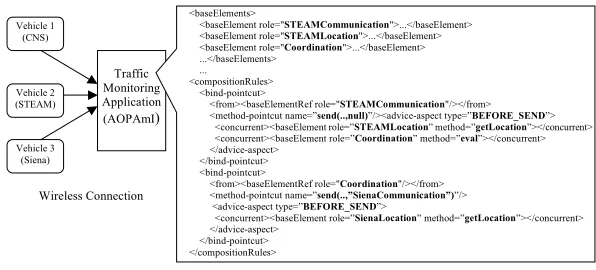
Fig. 2. The partial architecture of the FES.
1. Communication Concern. This concern implements the primitives to send and receive events using the event system communication protocols, and also to translate these events to the FES event format. They can be considered wrappers. 2. Location concern. Any application participating in an event system must be
3. Finally, the Coordination concern is in charge of communication between platform and the application level, which decides what to do with the delivered events. This concern takes platform context information and the own event contents into account in order to disseminate new events or discard received ones orchestrating the FES.
Following the example presented in section 2, and the general description of the AOPAmI platform provided in section 3, we are going to describe how these base elements are combined to implement the TM application and the advantages derived from that FES implementation. We have developed a set of communication base elements that wrap up each event system being integrated (e.g. STEAMCommunication base element). Let us suppose that a vehicle sends a STEAM event to the TM application containing data about the vehicle speed. In the platform the STEAMCommunication element will receive this event. After receiving the event, the element translates it to the FES event model and throws an AOPAmI event containing the original event as an argument. In order to throw this event the element executes the send method. The ACR that composes this base element with the rest of the platform and application components is shown in Fig. 2.
Now let us suppose that the Coordination element evaluates a second event from a previously warned vehicle. In this case, the vehicle must be registered and fined. Where the offending vehicle is using the Siena event system, the Coordination element sends a message to the SienaCommunication element. In this case we will need an ACR, the second one shown in Fig. 2, to compose the SienaCommunication with the SienaLocation element, in order to obtain a valid location to which to send the event, as that information is not available to the Coordination element.
<baseElements>
<baseElement role="SpeedFilter"> <impls selected="default">
<impl id="default" mainclass="BE.SpeedFilter"> <params>
<param id="speed_limit” value="60"/> ...
</params> </impl> </impls> </baseElement> ... </baseElements> ... <compositionRules> <bind-pointcut>
<from><baseElementRef role="STEAMCommunication"/></from> <method-pointcut name=”send(.., null)”/>
<advice-aspect type=”BEFORE_SEND”> <concurrent>
<baseElement role=”STEAMLocation” method=”getLocation”> </concurrent>
<concurrent><baseElement role=”SpeedFilter” method=”filter”></concurrent> <concurrent><baseElement role=” Coordination” method=”eval”></concurrent> </advice-aspect>
</bind-pointcut> ...</compositionRules>
public class SpeedFilter extends DefaultBaseElement{ long SPEED_LIMIT=0;
public SpeedFilter() {}
public void configure(String[][] args){ try{
for(int i=0;i<args.length;i++){
if(args[i][0].equals("speed_limit")) SPEED_LIMIT=Long.parseLong(args[i][1]); else{ } //Rest of configuration parameters.
}
} catch (Exception ex) {ex.printStackTrace();} }
public SystemEvent filter(SystemEvent evt){ try{
Argument arg=evt.getArg("speed"); long value=(Long)arg.getValue(); if(value>SPEED_LIMIT) return evt;
else return null; //Return a null value indicates an evaluation error. } catch (Exception ex) {
ex.printStackTrace(); return null; } } }/*End of class*/
[image:9.595.127.469.243.380.2]b a
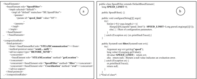
Fig. 3. Modified example.
After examining the previous example we have noticed a possible design flaw related to the application scalability. The Coordination element processes all delivered events independently whether they have to be processed or not by the application. Adding a SpeedFilter element able to discard speed events which include invalid speed information seems to be a good solution to this problem. To integrate this base element into the existing application, we add its description to the PA and modify the first CR as is shown in Fig. 3 (a). If we examine carefully the implementation of the SpeedFilter base element, shown in Fig. 3 (b), we notice that we have moved all the event checking code from the Coordination element to the SpeedFilter element, thus simplifying its implementation. We also notice that the speed limit is encoded as a base element initialization parameter which is used when the element is instantiated. As a consequence, we obtain more reusable SpeedFilter and Coordination base elements. Finally, we have introduced a new service in the FES that can be used by any integrated event system.
5 Conclusions
technological and the requirement application evolution and finally AOPAmI provides a mechanism to dynamically adapt the application to unforeseen events through the PA and the coordination base element. This has been possible thanks to the use of the aspect orientation paradigm in the platform.
Notice that this approach does not try to obtain the definitive FES, but provide a solution to easily accommodate new event systems in an existing FES application. In order to validate our proposal we have implemented a FES prototype using AOPAmI and perform simulations using different computers and event systems configurations. The prototype implementation was limited to the event systems used by the original application but nothing prevent us for integrating other event system models such as the web service notification models described by OASIS WS-Notification [12].
As future work, we are refining the AOPAmI platform implementation and working on a set of tools to automate, test and validate the Platform Architecture and facilitate the application development and deployment.
References
[1] ISTAG web site: http://www.cordis.lu/ist/istag.htm [2] Siena web site: http://serl.cs.colorado.edu/siena/
[3] Meier, R., Cahill, V.: STEAM: Event-Based Middleware for Wireless Ad Hoc Networks, Procd of the Int. Workshop on Distributed Event-Based Systems (ICDCS/DEBS'02), Vienna, Austria, (2002)
[4] Object Management Group, CORBAservices: Common Object Services Specification - Notification Service Specification, Object Management Group.
[5] AOSD web site: http://www.aosd.net/
[6] Fuentes, L., Jimenez, D. Pinto, M.: Development of Ambient Intelligence Applications using Components and Aspects, Journal of Universal Computer Science, Volume. 12, Issue 3, Thomson (2006) 236-251
[7] Ryan, C., Meier, R., Cahill, V.: Federating Heterogeneous Event Services, In Procd. of the 3rd Int. Workshop on Distributed Event-Based Systems (ACM/IEEE ICSE/DEBS'04), Edinburgh, Uk, (2004)
[8] Aleksy, M., Schader, M., Schnell, A.: Design and Implementation of a Bridge between CORBA’s Notification Service and the Java Message Service, University of Mannheim, Germany, Procd. of the 36th Int. Conference on System Sciences, (2003)
[9] Fuentes, L., Jimenez, D. Meier, R.: Implementation of an AmI Communication Service Using a Federated Event System Based on Aspects, Proc. of the 1 Int. Workshop on Software Engineering of Pervasive Services (SEPS 2006), Lyon, France, (2006)
[10] Frei, A.,Popovici, A., Gustavo, A.: Eventizing Applications in an Adaptive Middleware Platform. IEEE Distributed System Online, vol. 5, nº4, (2005)
[11] [AspectJ] Kickzales, G., et Al,: Aspect-Oriented Programming. European Conference on Object Oriented Software Development (ECOOP’97), Jyväskylä, Finland, (1997)