http://www.scirp.org/journal/am ISSN Online: 2152-7393
ISSN Print: 2152-7385
DOI: 10.4236/am.2017.89092 Sep. 6, 2017 1227 Applied Mathematics
Modified Kuramoto Phase Model for Simulating
Cardiac Pacemaker Cell Synchronization
Motohisa Osaka
Department of Basic Science, Nippon Veterinary and Life Science University, Tokyo, Japan
Abstract
It has been suggested that sick sinus syndrome, which is due to the dysfunc-tion of the sinus node, may result from the sparser gap juncdysfunc-tions and/or lower intrinsic frequencies of pacemaker cells that occur with aging. Hence, in this paper, the synchronization mechanism of pacemaker cells that lie in the sinus node of the heart is examined using a modified Kuramoto phase model. Al-though each element always interacts with all the others in the Kuramoto phase model, in the proposed model, each element interacts only with the neighbors over a certain time (called the interaction time) during Phase 4 of the action potential. The pacemaker cell elements are arranged on a square lattice, and each element connects with the elements surrounding it. The re-sults indicate that the diversity of intrinsic frequencies of pacemaker cells may be necessary for synchronization. Moreover, increasing the proportion of invalid connections causes the elements to take more time to synchronize un-til eventually they do not synchronize at all, and decreasing the intrinsic fre-quencies of the elements prevents them from synchronizing. Probably these elucidate the cause of sick sinus syndrome.
Keywords
Synchronization, Sick Sinus Syndrome, Oscillator, Overdrive Suppression Test, Gap Junction
1. Introduction
Synchronization is a universal phenomenon associated with oscillations. The Moon revolves around the Earth with the same period as that of its rotation. The tide-producing force from the Earth to the Moon causes the synchronization of the revolution and rotation of the Moon. Moreover, the spontaneous synchro-nization of firefly lights is one of several extremely fascinating exhibitions that
How to cite this paper: Osaka, M. (2017) Modified Kuramoto Phase Model for Si-mulating Cardiac Pacemaker Cell Synchro-nization. Applied Mathematics, 8, 1227-1238.
https://doi.org/10.4236/am.2017.89092 Received: August 16, 2017
Accepted: September 3, 2017 Published: September 6, 2017 Copyright © 2017 by author and Scientific Research Publishing Inc. This work is licensed under the Creative Commons Attribution International License (CC BY 4.0).
DOI: 10.4236/am.2017.89092 1228 Applied Mathematics occur in nature. Some mathematical models have been proposed to simulate this phenomenon [1]. Each firefly is assumed to be a light-emitting oscillator that generates a limit cycle. Another example is the synchronization of a series of Jo-sephson junctions, each element of which interacts only with its close neighbors [2]. Similarly, each pacemaker cell of the sinoatrial node (a group of pacemaker cells in the wall of the right atrium of the heart), which is regarded as an electric-al oscillator generating a limit cycle, is loosely coupled with its neighboring pa-cemaker cells so that those cells synchronize. The electrical impulse current of a single pacemaker cell is not sufficient to travel through the impulse-conducting system, so the ventricles of the heart do not contract. In contrast, synchronized pacemaker cells generate an impulse with sufficiently high current to travel through the system so that the ventricles contract and pump out blood normally. Hence, the failure of this synchronization is presumed to cause sinoatrial arrest [3]. This interruption of the cardiac cycle generally lasts a few seconds before the atrioventricular junction lying in the middle of the impulse-conducting system begins pacing and restores slower ventricular contractions. Sinoatrial arrest is a part of sick sinus syndrome, the symptoms of which include fainting, vertigo, and weakness. Gap junctions in the sinoatrial node have recently been demon-strated to be a key player in the electrical coupling underlying synchronization [4]. Because gap junctions have low resistance, local circuit currents propagate over short distances. Jalife proposed a very probable hypothesis called the dem-ocratic consensus hypothesis, which is based on an experiment using rabbit si-noatrial pacemaker cells [5]. This hypothesis states that although the individual pacemaker cells in the sinoatrial node beat at slightly different intrinsic frequen-cies, they interact mutually by electrical coupling to fire at a “consensus” rate. It has been suggested that when two independent groups of fast and slow pace-maker cells are connected through low-resistance junctions, the period resulting from their mutual entrainment should be a function of their respective intrinsic frequencies, their phase relations, and the degree of electrical coupling. Moreo-ver, Jalife et al. elucidated the mechanisms of sinoatrial pacemaker synchroniza-tion using a computer simulasynchroniza-tion of 81 to 225 coupled cells [6]. Pacemaker ac-tivity has been simulated using differential equations that describe transmem-brane ionic currents. These results support the hypothesis that sinoatrial node synchronization occurs through a “democratic” process resulting from the phase-dependent interactions of thousands of pacemakers.
be-DOI: 10.4236/am.2017.89092 1229 Applied Mathematics tween fast and slow pacemaker cells, that is, simple harmonic (e.g., 1:1, 2:1, and 1:2) and more complex (e.g., 3:2 and 5:4) ratios [5]. Because such complex phe-nomena have not been reported in the observation of firefly signals, we speculate that these various ratios may be due to the refractory period. Specific ionic cur-rents, over time, slowly depolarize Phase 4 for pacemaking. Hence, it is assumed that each pacemaker cell is influenced by its neighbors, the phases of which are within a certain range of its phase. This range is called the interaction time. We modified the Kuramoto phase model by incorporating a variable that represents the period of Phase 4. In the modified Kuramoto phase model, for each pace-maker cell, the intrinsic frequency, Phase 4 period, phase relation, and degree of coupling between it and the neighboring pacemaker cells can be modulated in-dependently as variables to observe various patterns. The differences between the Kuramoto phase model and the proposed model are that although each ele-ment always interacts with all the others in the former, each eleele-ment interacts only with its neighbors during the Phase 4 period in the latter. We examine how the synchronization of pacemaker cells depends on those variables. Such an ex-amination is presumed to be rather difficult using differential equations de-scribing transmembrane ionic currents.
The repetitive high-frequency stimulation test of the sinoatrial node (called the overdrive suppression test) is used to examine its function clinically. The si-noatrial node comes to a standstill immediately after the repetitive stimulation, then resumes a regular rhythm after a certain pause (called the sinus node re-covery time). The length of this pause is presumed to reflect the degree of dys-function of the sinoatrial node [8][9]. Although some mechanisms of this dys-function have been described [10], the factor that determines the length of the sinus node recovery time is unknown. One of the purposes of the present study is to infer that factor using the modified Kuramoto phase model. Additionally, an unexpected finding is that slightly different intrinsic frequencies of the pace-maker cell elements promote their synchronization, although it was expected that the same frequencies would make those elements synchronize more easily.
2. Model
DOI: 10.4236/am.2017.89092 1230 Applied Mathematics
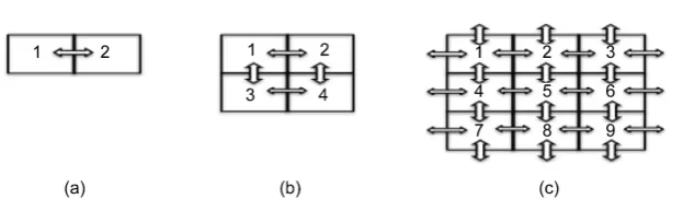
Figure 1. Arrangement of coupling resistances between simulated pacemaker cells in
two-dimensional square lattices. The resistances are expressed as arrows. (a) 2 elements; (b) 2 × 2 elements; and (c) 3 × 3 elements. Every element interacts with four elements, and (c) shows that every element on the sides connects with its immediate neighbors and elements on the opposite side.
posite side. Because every element is equivalent to the others with respect to po-sition, no boundary condition is necessary. Hence, this two-dimensional lattice is assumed to be the surface of a three-dimensional torus made by connecting the top side with the bottom and the left side with the right. The elements di-rectly connected in this manner are regarded as neighbors. In the modified Ku-ramoto phase model, the dynamics of the i-th cell (i=1, 2, 3,,n) is represented
as follows:
(
)
(
)
(
)
(
)
(
(
(
)
)
)
(
)
1 d 1 sin d1 sign rem , 2π π
2
1 sign rem , 2π π 1 sign rem ,2π π
; 2 m m m N i
i ii i i
m
i i i
i i i
f K
t N
G
H
θ θ θ
θ θ θ θ = = − − − − − × × − + − − × ×
∑
(1)In this equation, n is the total number of the elements of the lattice, θi is the phase of the i-th element, fi is the intrinsic frequency of the i-th element, N is the number of couplings with the i-th element (N = 1 in Figure 1(a), 2 in Figure 1(b), and 4 in Figure 1(c)), and Kiim is the degree of interaction between the i-th and im-th elements. For example, imfor the first element of Figure 1(c) are 2, 3, 4, and 7, and imfor the fifth element is 2, 4, 6, and 8. The rem function is the remainder operation: r=rem
( )
a b, returns the remainder after the division of a by b and the result has the same sign as dividend a. For example,(
)
rem −5π,2π = −π. Function y = sign(x) returns 1 if x > 0, 0 if x = 0, and −1 if x < 0. Moreover, Gi and Fi are coefficients between 0 and 2. The phase of every cycle is 2π.
The first line of the equation is just the Kuramoto phase model for the inte-ractions between each element and its neighbors. The second line returns 1 if the difference between θi and
m
i
θ
, for any integer multiple of 2π, is less than π × Gi,0 if it is larger than π × Gi, and 1/2 if it is equal to π × Gi. However, it is assumed
never to equal to π × Gi exactly. Hence, the second line means that only if the
DOI: 10.4236/am.2017.89092 1231 Applied Mathematics
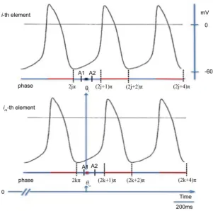
Figure 2. Schema of the action potentials of i-thelement and its im-thneighbor. Red line,
refractory period; Blue line, Phase 4.θi, phase of the i-th element (black circle);
m
i
θ ,
phase of the im-th neighbor (red circle). A1, rem(θi, 2π) —π × Gi; A2, rem(θi, 2π) + π × Gi.
(
)
rem
θ
i, 2π ≥0, the third line returns 1 if rem(
θ
i, 2π)
is less than π × Hi, 0 if itis larger than π × Hi, and 1/2 if it is equal to π × Hi. When rem
(
θ
i, 2π)
<0, the third line returns 1 if rem(
θ
i, 2π 2π)
+ is less than π × Hi, 0 if it is larger than π× Hi, and 1/2 if it is equal to π × Hi. It is also assumed neither to be exactly equal to π × Hi nor to be < 0. Thus, the third line means that only if the phase of the
i-th element, for any integer multiple of 2π, is between 0 and π × Hi is the i-th
element influenced by the neighbors. Figure 2 shows trains of action potentials for two pacemaker cells. The action potential mainly consists of Phases 0, 3, and 4, because Phases 1 and 2 are small. Phase 0 is the period of rapid depolarization caused by a fast inflow of calcium ions and Phase 3 consists of repolarization caused by a fast outflow of potassium ions. These periods make up the refractory period. Phase 4 is the period during which the inflow of sodium ions begins, and thereafter, the inflow of calcium ion continues before firing beyond the thre-shold [11]. Because the i-th element interacts with the neighbors during Phase 4 and the ionic current through the gap junctions depends on the phase, it is pre-sumed that elements interact with each other when the neighbors are in or near Phase 4. Using π × Gi, any element influencing the i-th element is restricted to
neighbors in or near Phase 4 correctly from rem
(
θ
i, 2π π)
− ×Gi to(
)
rem
θ
i, 2π π+ ×Gi. The interaction time is defined as π×Gi×2. This is theDOI: 10.4236/am.2017.89092 1232 Applied Mathematics The assumptions are summarized as follows:
Assumption 1: The elements are independent oscillators. In the Kuramoto phase model, each element interacts with all the others. In contrast, in the pro-posed model, each element interacts only with the connecting elements (neigh-bors).
Assumption 2: The frequency of each element varies marginally around a certain common frequency. Hence, Fi, the intrinsic frequency of the i-th element
(i=1, 2, 3,,n), is the sum of a common frequency Fc and random frequency
i
r
F . Common frequency Fc is fixed as 0.4 arbitrarily. The random frequency is given individually and is generated from a uniform distribution of random numbers between 0 and 0.1. Then, Fri is denoted as (0, 0.1) (Table 1, Table 2). Hence, 0.4
i
i r
F = +F .
Assumption 3: The degree of interaction between two neighbors varies mar-ginally around a certain common degree. Hence, Kiim, the degree of interaction between the i-th element and its im-th neighbor, is the sum of a common degree Kc and random degree Krim. The random degree is given individually and is
generated from a uniform distribution of random numbers between 0 and 1. Then, Krim is denoted as (0, 1) (all Tables). Hence, Kiim =Kc+Kirim.
Assumption 4: The duration of Phase 4 is represented as π×Hi, during which
the i-th element interacts with the neighbors. The value of Hi is from 0 to 1. For the sake of model simplicity, it is the same for all elements. Hence, all Hi are ex-pressed as H. The phase of one cycle is 2π. Because the duration of Phase 4 (=π ×
[image:6.595.55.543.450.552.2]H) is approximately one half of one cycle [11], H is assumed to be 1. The start
Table 1. Effects of Fr, Gc, and lattice size on synchronization (SYNC).
2 Elements 9 Elements 16 Elements 36 Elements 100 Elements 121 Elements 144 Elements Fc Fr Gc Gr Kc Kr SYNC (cy) SYNC (cy) SYNC (cy) SYNC (cy) SYNC (cy) SYNC (cy) SYNC (cy)
0.4 0 0.2 (0, 0.2) 1 (0, 1) none none none none none none or 12.5 (u) none or 12.5 (u) 0.4 (0, 0.1) 0.2 (0, 0.2) 1 (0, 1) none 14 14 14 14 14 13.5 0.4 0 0.8 (0, 0.2) 1 (0, 1) none 13 13 13 12.8 12.8 12.8 0.4 (0, 0.1) 0.8 (0, 0.2) 1 (0, 1) 14 14.5 14 14 14 13.5 13.5
cy: cycles/2000 time steps; u: unstable.
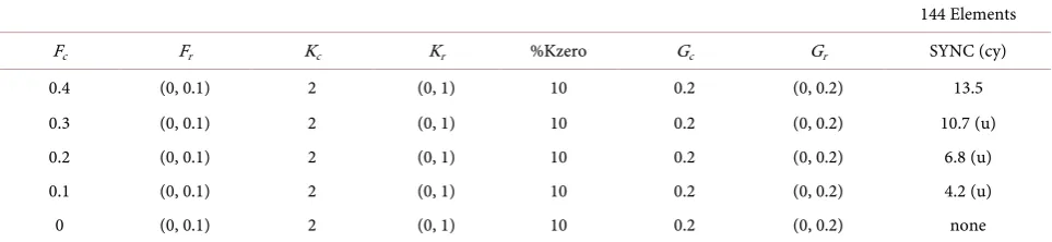
Table 2. Effects of lower common frequency on synchronization (SYNC).
144 Elements Fc Fr Kc Kr %Kzero Gc Gr SYNC (cy)
0.4 (0, 0.1) 2 (0, 1) 10 0.2 (0, 0.2) 13.5 0.3 (0, 0.1) 2 (0, 1) 10 0.2 (0, 0.2) 10.7 (u) 0.2 (0, 0.1) 2 (0, 1) 10 0.2 (0, 0.2) 6.8 (u) 0.1 (0, 0.1) 2 (0, 1) 10 0.2 (0, 0.2) 4.2 (u) 0 (0, 0.1) 2 (0, 1) 10 0.2 (0, 0.2) none
[image:6.595.57.539.599.710.2]DOI: 10.4236/am.2017.89092 1233 Applied Mathematics
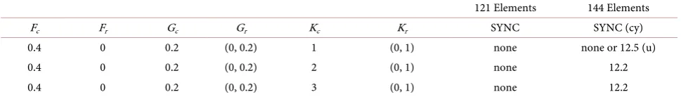
Table 3. Effects of Kc, and lattice size on synchronization (SYNC).
121 Elements 144 Elements Fc Fr Gc Gr Kc Kr SYNC SYNC (cy)
0.4 0 0.2 (0, 0.2) 1 (0, 1) none none or 12.5 (u) 0.4 0 0.2 (0, 0.2) 2 (0, 1) none 12.2 0.4 0 0.2 (0, 0.2) 3 (0, 1) none 12.2
cy: cycles/2000 time steps; u: unstable.
point of Phase 4 is defined as 2jπ (Figure 2). Because rem
(
,2π)
mi
θ
is between A1 and A2 in this figure, the im-th neighbor influences the i-th element. When(
)
rem ,2π
m
i
θ
is not between A1 and A2, the im-th neighbor does not influence the i-th element.Assumption 5: When the phase of the i-th element, for any integer multiple of 2π, is between 0 and π × Hi, any neighbor of the i-th element is restricted to
the neighbors with a phase between θ − ×i π Gi and θ + ×i π Gi for any integer
multiple of 2π. The value π×Gi×2 is called the interaction time. The value of Gi is from 0 to 1, and varies marginally around a certain common value. Hence, Gi is the sum of a common value Gc and a random value Gri. The random value is given individually and is generated from a uniform distribution of random numbers between 0 and 0.2. Hence, Gri is denoted as (0, 0.2). Further,
i
i c r
G =G +G .
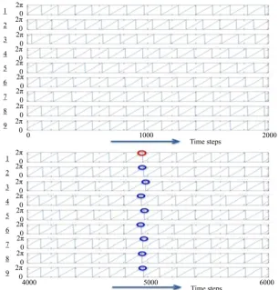
Assumption 6: The mean Mf and standard deviation SDf of the frequencies of all elements are calculated over a period 2000 time steps in length (unit of fre-quency, cy: cycles/2000 time steps) (Figure 3). An arbitrary peak of rem
(
θ
1, 2π)
is employed as a reference peak. One cycle is 2,000/Mf time steps. The difference between the time step at the reference peak and a time step at each of the other peaks of rem(
θ
i, 2π)
, i≥ 2, is calculated. The standard deviation of these dif-ferences is divided by the time steps of one cycle. This quotient is denoted by SDp (no units). When 0≤SDf ≤0.1 M× f and 0≤SDp≤1 8, it is considered that the elements synchronize with respect to frequency and phase (frequency- and phase-synchronization). This means that about 95% of frequencies are between Mf × 0.8 and Mf × 1.2 and about 95% of the peak phases are between the phase of the reference peak −π/2 and the phase of the reference peak +π/2 because theDOI: 10.4236/am.2017.89092 1234 Applied Mathematics
Figure 3. Example showing calculation of the mean Mf and standard deviation SDf of the
fre-quencies of nine elements as well as the standard deviation SDp of the differences between the
phases of the peaks. Here, Mf and SDf are calculated over 2000 time steps (unit of frequency, cy:
cycles/2000 time steps). The parameters are defined in Table 1 (Fc = 0.4, Fr = (0, 0.1), Gc = 0.2,
Gr = (0, 0.2), Kc = 1, and Kr = (0, 1)). Each ordinate is rem
(
θi, 2π)
(i=1, 2,, 9).One cycle is 2000/14.0 = 142.9 time steps. Because SDp = 0.08, the condition p
0≤SD ≤1 8 is satisfied. Hence, frequency- and phase-synchronization occurs.
The phases θi (i=1, 2, 3,,n) are calculated using MATLAB® to solve the
diffe-rential equations. The calculation precision depends on the time step. Although 2 time steps, 0.1 and 0.01, have been used preliminarily, both have given the same results to calculate frequency. Hence, time step 0.1 is selected. It is needed that the time span is long enough to examine whether the elements synchronize or not. The time span is from 0 to 2000 (if necessary, 6,000). Hence, the data length of θi (i=1, 2, 3,,n) is 20,000 (or 60,000) time steps. The initial
condi-tion is a set of uniformly distributed random numbers in the interval (0, 5).
3. Simulation Results
1) Effects of Fr, Gc, and lattice size
syn-DOI: 10.4236/am.2017.89092 1235 Applied Mathematics chronization of the elements depends on the lattice size. Specifically, when Gc = 0.2, the elements barely synchronize when the lattice size is small and the syn-chronization is unstable. In contrast, when Gc = 0.8, smaller lattices, even lattices of only nine elements, synchronize stably. Table 3 shows that when all Fri equal zero, 121-element lattices do not synchronize, even when Kc = 3. In contrast, a 144-element lattice (12 × 12 elements) synchronizes when Kc < 3.
2) Effect of fewer connections between neighbors
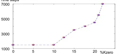
Each element connects with four neighbors. For example, a 144-element lattice has 290 different connections. Here, the percentage of invalid connections with respect to total connections is denoted as %Kzero. When Fc = 0.4, Fr = (0, 0.1), Kc = 2, Kr = (0, 1), %Kzero = 10, Gc = 0.2, and Gr = (0, 0.2), a 144-element lattice synchronizes with a %Kzero of less than 23 (Figure 4). As %Kzero increases, it takes the elements longer to synchronize (a longer delay).
3) Effects of a lower common frequency on synchronization
Assumption 2 states that the frequency of each element varies marginally around a certain common frequency. Hence, Fi is the sum of common frequency Fc and random frequency Fri. Several cases in which Fc is varied from 0.4 to 0 are examined (Table 2). When Fc is lower, the elements synchronize less unstably and ultimately do not synchronize at all. In other words, as the ratio of Fc to Fri is lower, the elements hardly synchronize.
4. Discussion
The findings of the simulation and their interpretations are as follows:
1) When all Fri equal zero and Gc is small in a small lattice, the elements do not synchronize. In contrast, even if all Fri equal zero, the elements of a small lattice synchronize with large Gc. Assumption 5 states that the elements influen-cing the i-th element are restricted to neighbors with a phase between
π
i Gi
[image:9.595.250.501.513.629.2]θ − × and θ + ×i π Gi for any integer multiple of 2π. The findings indicate
Figure 4. Effect of fewer connections between neighbors. %Kzero:
the percentage of invalid connections with respect to total connec-tions. The ordinate is a delay in synchronization. The conditions of parameters: Fc = 0.4, Fr = (0, 0.1), Kc = 2, Kr = (0, 1), %Kzero = 10,
Gc = 0.2, and Gr = (0, 0.2). The delay becomes longer exponentially
DOI: 10.4236/am.2017.89092 1236 Applied Mathematics that elements with the same frequencies barely synchronize when Gc is small. When the lattice size is bigger, the cells synchronize. In the initial condition, the phases of the elements are uniformly random. Because an element interacts only with the neighbors with a similar phase, the probability that it is influenced by neighbors decreases as Gc decreases. Hence, when the frequencies (that is, phas-es) of the elements are more varied, this probability increases. This suggests that the diversity of frequencies (or phases) of the elements is necessary for the ele-ments to synchronize. This suggestion is supported by the fact that the eleele-ments of smaller lattices synchronize easily when Fr does not equal zero or when Gc is larger. When Fr equals zero, a 121-element lattice does not synchronize even when Kc = 3. In contrast, a 144-element lattice synchronizes when Kc < 3. These findings suggest that the diversity of frequencies is more effective for element synchronization than the strength of interaction between neighboring elements.
2) The synchronization of a 144-element lattice occurs when Gc = 0.2, Kc = 2, and %Kzero < 23. It has been reported that gap junctions are sparser in the si-noatrial node than in the surrounding atrial muscle [12]. Hence, this report sug-gests that %Kzero, which corresponds to the percentage of invalid gap junctions, is greater than zero. In the present study, the synchronization for generating an impulse traveling through the stimulating conducting system is assumed to be frequency- and phase-entrainment. When Gc is large, each element can be af-fected by the phases of its neighbors that are rather different from its phase. In this case, although frequency entrainment occurs easily, phase-entrainment does not also occur. Hence, small Gc is necessary for phase-entrainment. These con-siderations indicate that the conditions Fc = 0.4, Fr = (0, 0.1), Kc = 2, Kr = (0, 1), %Kzero = 10, Gc = 0.2, and Gr = (0, 0.2) for the elements, are likely conditions for simulating pacemaker cells. If %Kzero is increased, it takes the elements more time to synchronize (Figure 4). Since the delay becomes longer exponentially beyond %Kzero = 10, the elements will not synchronize abruptly at %Kzero = 23. It suggests that the maximum sinus node recovery time (clinically about 1.5 s [8]) appears around %Kzero = 23.
DOI: 10.4236/am.2017.89092 1237 Applied Mathematics 3) The results also suggest that if the common frequency is lower, the elements do not synchronize when %Kzero = 10, Gc = 0.2, and Kc = 2. These conditions are selected because the second finding above indicates that they are suitable for simu-lating pacemaker cells. It has been reported that the intrinsic frequencies of pace-maker cells decreases with aging [14]. This phenomenon may be simulated by lower Fc. It is presumed to be one of mechanisms that cause the sinoatrial node to be unable to synchronize steadily and could be an age-related cause of sick sinus syndrome. On the other hand, intrinsic heart rate of normal subjects is rather fast [14]. The reason for this was for a long time unknown. Heart rate is controlled within a normal range of 60 to 100 beats per minute under the autonomic nervous control. Since the elements hardly synchronize with the ratio of Fc to Fri being lower, a high ratio of Fc to Fri is necessary for synchronization. Probably, this is the reason that intrinsic heart rate of normal subjects is rather fast.
4) Study limitations
The largest lattice size is 144 elements (12 × 12 elements). It takes about six hours to solve 144 differential equations using MATLAB®. It takes too long to calculate a lattice with 225 elements (15 × 15 elements) in practice. Hence, the maximum lattice size in the present study is 144 elements. This model is de-scribed using some parameters for frequency, the period of Phase 4, and interac-tion. Although values for these parameters that simulate pacemaker cells were determined from many trial-and-error experiments, the validity of these values should be investigated in the future.
5. Conclusion
In this study, the Kuramoto phase model was modified by incorporating the interaction time of Phase 4, during which each element can interact with its neighbors, as a variable. The results are as follows: 1) Certain values for the frequency, interaction time, and degree of interaction are found to simulate pacemaker cells; 2) Diversity in the intrinsic frequencies of the elements pro-motes their synchronization, although the same frequencies should be easier to synchronize; 3) Increasing the proportion of invalid connections in the model (which corresponds physiologically to sparser gap junctions) causes the ele-ments to take longer to synchronize and eventually become unable to syn-chronize at all; 4) Decreasing the intrinsic frequencies of the elements prevents them from synchronizing. These results indicate a possible mechanism for the age-related causes of sick sinus syndrome.
Conflict of Interests
The author declares that there is no conflict of interests regarding the publica-tion of this paper.
References
DOI: 10.4236/am.2017.89092 1238 Applied Mathematics Oscillators. SIAM Journal on Applied Mathematics, 50, 1645-1662.
https://doi.org/10.1137/0150098
[2] Josephson, B.D. (1962) Possible New Effects in Superconductive Tunnelling. Phys-ics Letters, 1, 251-253.https://doi.org/10.1016/0031-9163(62)91369-0
[3] Glass, L. (2001) Synchronization and Rhythmic Processes in Physiology. Nature, 410, 277-284.https://doi.org/10.1038/35065745
[4] Verheule, S., van Kempen, M.J.A., Postma, S., Rook, M.B. and Jongsma, H.J. (2001) Gap Junctions in the Rabbit Sinoatrial Node. American Journal of Physiology—Heart and Circulatory Physiology, 280, H2103-H2115.
[5] Jalife, J. (1984) Mutual Entrainment and Electrical Coupling as Mechanisms for Synchronous Firing of Rabbit Sino-Atrial Pace-Maker Cells. Journal of Physiology, 356, 221-243.https://doi.org/10.1113/jphysiol.1984.sp015461
[6] Michaels, D.C., Matyas, E.P. and Jalife, J. (1987) Mechanisms of Sinoatrial Pace-maker Synchronization: A New Hypothesis. Circulation Research, 61, 704-714.
https://doi.org/10.1161/01.RES.61.5.704
[7] Strogatz, S. (2000) From Kuramoto to Crawford: Exploring the Onset of Synchro-nization in Populations of Coupled Oscillators. Physica D: Nonlinear Phenomena, 143, 1-20.https://doi.org/10.1016/S0167-2789(00)00094-4
[8] Mandel, W., Hayakawa, H., Danzig, R. and Marcus, H.S. (1971) Evaluation of Si-no-Atrial Node Function in Man by Overdrive Suppression. Circulation, 44, 59-56.
https://doi.org/10.1161/01.CIR.44.1.59
[9] Mandel, W., Hayakawa, H., Allen, H.N., Danzig, R. and Kermaier, A.I. (1972) As-sessment of Sinus Node Function in Patients with the Sick Sinus Syndrome. Circu-lation, 46, 761-769.https://doi.org/10.1161/01.CIR.46.4.761
[10] Gaffney, B.J., Wasserman, A.G., Rotsztain, A. and Rios, J.C. (1980) Sick Sinus Syn-drome: Mechanisms and Management. Cardiovascular Clinics, 11, 7-25.
[11] Ito, H., Ono, K. and Noma, A (1994) Background Conductance Attributable to Spontaneous Opening of Muscarinic K+ Channels in Rabbit Sino-Atrial Node Cells. Journal of Physiology, 476, 55-68.
[12] Masson-Pevet, M.A., Bleeker, W.K. and Gros, D. (1979) The Plasma Membrane of Leading Pacemaker Cells in the Rabbit Sinus Node: A Quantitative Ultrastructural Analysis. Circulation Research, 45, 621-629.
https://doi.org/10.1161/01.RES.45.5.621
[13] Yeh, H.I., Chang, H.M., Lu, W.W., Lee, Y.N., Ko, Y.S., Severs, N.J. and Tsai, C.H. (2000) Age-Related Alteration of Gap Junction Distribution and Connexin Expres-sion in Rat Aortic Endothelium. Journal of Histochemistry & Cytochememistry, 48, 1377-1389.https://doi.org/10.1177/002215540004801008
Submit or recommend next manuscript to SCIRP and we will provide best service for you:
Accepting pre-submission inquiries through Email, Facebook, LinkedIn, Twitter, etc. A wide selection of journals (inclusive of 9 subjects, more than 200 journals)
Providing 24-hour high-quality service User-friendly online submission system Fair and swift peer-review system
Efficient typesetting and proofreading procedure
Display of the result of downloads and visits, as well as the number of cited articles Maximum dissemination of your research work
Submit your manuscript at: http://papersubmission.scirp.org/