THE MISSING LINK IN DATA PROCESSING
O
l
D
CONTROL DATA CORPORATION
RELIABI L1TY
AT THE SOURCE
NOW PROVIDED BY
THE
180
DATA COLLECTOR will help you exercise more effective management control from the very first step in any operation, the gathering of facts.It provides you with instantly available, on-the-spot information- for production scheduling, machine loading, schedule and incentive payroll planning, cost and inven-tory control, and many other areas of exec-utive responsibility.
THE
180
DATA COLLECTOR does this by preparing a record while work is being per-formed- a combined record which includes time, standard job information, employee identification, and other facts which you may desire. This on-the-job record is instantly recorded so that it may be taken without delay to the data processing department.THE
180
DATA COLLECTOR is the most efficient data gathering device known. It is fast, simple to operate, tamper-proof, and low in cost. Here is a quick summary of advantages:• enables you to make faster decisions
• eliminates handwriting errors in reporting
• cuts paper work
• increases accuracy
• reduces the number of reporting personnel needed
• easily operated ... requires no special training
• does not "lock out" ... no waiting to transmit
• operates on regular plant voltages ... no facility changes needed
• features multiple card transmission per cycle ... far faster than single card systems
1"_IIIIII~_.,
~
1
I
THE
180
DATA COLLECTOR
SPEEDS REPORTING-Because data is both entered and converted at the point of origin, it can be taken directly from the Collector to the data processing
depart-ment. There it can be fed into computers and tabulating equipment for further processing.
MAKES DECISIONS EASIER-The 180 Data Collector helps you exercise more effective management control because you act on current information, swiftly obtained, and accurately reported. You can act more rapidly, more decisively, and with greater assurance that your decision is correct.
r---
II I I
I I
I I
I
NO INSTALLATION COST- The 180 Data Collector is a modular, self-contained unit.
It can be wall mounted. or placed upon a table or desk. You can move it wherever needed, and there are no installation costs to pay ...
no expensive communication, power, or cen-tral system changes to make. Should your needs grow, it is as simple to add more 180 Data Collectors as it is to place more type-writers in your office.
FASTER TRANSMISSION, NO LOST
TIME-The 180 Data Collector saves time and pa-tience. It has its own data output unit, which means that the operator does not have to wait to enter his data. With other collection systems, it is often necessary to stand by while a single recording station clears to receive the data. The 180 Data Collector eliminates this time consuming, troublesome bottleneck. Further-more, since there are no commun~cation lines, there can be no communication line failure, and error cannot be introduced in transits.
FUNCTION
VARIABLE DATA
The operator enters this data by dial settings. For example, job lot nume ber, shrinkage, amount produced.
IDENTIFICATION DATA
The operator enters this data from pre-punched cards. For example, employee number, machine number, material identification.
FIXED DATA
This data is contained in the internal memory of the Collector. For exam-ple, department number, plant location, collector station number.
REAL-TIME CLOCK
Time is read out and automatically
combined with each recorded
trans-action.
DATA OUTPUT
The combined output record length
VARIABLE INPUTS
are manually set by 10 multi-position rotary switches, provided for theinsertion of count and process information. This
information is automatically entered in the
out-put record.
IDENTIFICATION DATA
is entered through thecard sensing unit, which reads a predetermined sequence of pre-punched cards. A built-in card sequence control prevents cards from being entered
improperly. The card reader is a unique
develop-ment of Control Data Corporation. It employs a pneumatic principle, proved more reliable and
rugged. Variable length cards may be used; bent or
wrinkled cards can be read reliably. Optional deci-mal or alphanumeric available.
FIXED DATA
inputs are provided by 6multi-position rotary switches, which provide for the
insertion of location, position, and collector
sta-tion numbers. These switches are behind a locked panel. They are set by supervisory personnel.
AN ELECTRIC CLOCK
automatically recordsthe time of each transaction, to the nearest 0.01 of an hour. The clock reset is behind a locked panel
- only supervisory personnel can set it. The time
can be read from a decimal display on the front of
the Collector. It is a 24 hour clock, operating on
115v,60 cycles, AC. Battery-driven or spring
wound clocks are available.
THE DATA OUTPUT UNIT
punches 16charac-ters per second on 8-level paper tape. Units of 5,
6 or 7-level tape are available.
SEQUENCE CONTROL
is automatic. Adistribu-tor scans the input cards, clock, variable inputs,
and fixed inputs, and translates from card code to
output record code. It also controls output punch.
ERROR SAFEGUARDS
include a push buttonwhich "voids" the preceding transaction,
inter-locks which assure proper card sequence, and a locked "on-off" switch which prevents accidental or illegal introduction of data. Also, a locked cover plate guards the clock and the interior of the Collector.
AUTOMATIC CLOCK-IN MODE
is provided topermit employees to use the Collector as a time
clock at the beginning and end of a shift. The
in-ternal clock automatically shifts from the
trans-action mode to the clock-in mode and vice versa.
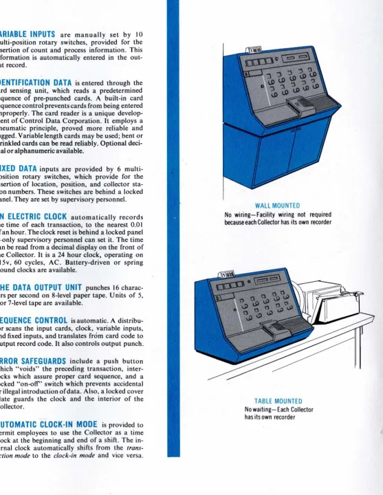
WALL MOUNTED
No wiring-Facility wiring not required because each Collector has its own recorder
TABLE MOUNTED
[image:5.601.43.600.48.768.2]INTEGRATED DATA PROCESSING
~---I
I I
I
I I I I
I I I I
MANAGEMENT
I
~---~
INTEGRATED DATA PROCESSING
PRESET
( 1) Fixed data entered prior to sequence of recording operations
SEQUENCE OF OPERATIONS
(1) Operator sets variable data source dials
(2) First identification card is inserted and
"transmit" button pressed
(3) Remaining identification cards inserted
DATA PROCESSING
(1) Output data tapes are taken to the data
processi ng department
(2) Tape is fed into memory of computer or
into tabulating equipment and processed
(3) Processed results are prepared for
management
MANAGEMENT
( 1) Reports read and analyzed
(2) Decisions made and action taken
-
-
---APPLICATIONS
Production scheduling. I ncentive payroll • Hotels. Cost control systems. Inventory control. Retailing. Quality control. Wholesaling
• Billing operations. Finance company records. Sales statistics. Banks. Purchasing • Airlines. Hospital patient charges
SPECI FICATIONS
INPUTS
IBM cards: Up to four 80-column card inputs
(320 characters) can be read. Also, stub
cards can be read. Alphanumeric optional.
Fixed data: Six m u It i -po sit ion rot a r y
switches for insertion of fixed information.
Variable data: Ten multi-position rotary switches for pre-setting variable information by operator.
Internal clock: 24 hour clock with .01 hour increments automatically recorded with each transaction.
OUTPUTS
Data Output Unit: 8-level punched paper
tape, recorded at 16 characters per second.
(5-,6-, or 7-level tape optional).
DIMENSIONS
Collector unit: 16" high by 17" wide by 13"
deep. Weight, 60 Ibs.
"
I)
A DESCRiPTION OF THE
180 SOURCE DATA COLLECTOR
SYSTEM OPERATING AT
CEDAR ENGINEERING DIVISION
Cedar Engineering Division of Control Data Corporation has wide experience in the design and manufacture of miniature electrical
and electro-mechanical devices. A cross-section of Cedar's product
line includes miniature Rotary Devices, Linear Acceleration devices, Control Amplifiers, complete Servo and Time-Function Assemblies, and supporting activities related to missile programs and other mili-tary applications.
One of the Division's newest developments is the 180 Source Data Collector which provides more efficient management control from the very first step in any operation--the collection of facts. Truly integrated data processing depends on an efficient, automatic method of collecting on-the-spot information. The 180 provides the method of collecting information which provides management control of operations such as production, scheduling, inventory control,
incentive payroll, job recording, job costing, and so on. Such a system, built around the 180 Source Data Collector, has been installed in
The Cedar Engineering Division I conducts its manufacturing
operation with some 2000 different part numbers.' The 180 Data Collector collects data on these varied part numbers and the derived finished products so that timely management reports can be made.
Five 180 Data Collectors will supply the input data for final resolution--four 180 I S monitor the production process and the fifth
is used for inventory control. The full operation I with all the complex
data involved I actually presents a rather simple and thus highly
efficient step-by-step procedure.
The specification profile of the 180 Source Data Collector is recorded here as an easy reference point for the system description:
INPUTS
IBM cards: Up to four 80-column card inputs (320) characters can be read. Also I stub cards can be read.
Fixed data: Six multi-position rotary switches for insertion of fixed information.
Variable data: Ten multi-position rotary switches for presetting variable information by operator.
Internal clock: 24 hour clock with. 0 1 increments automatically recorded with each transaction.
OUTPUTS
Data Output Unit: 8-level punch'ed paper tape I recorded at 16
characters per second. (5-I 6- I or 7-level tape
optional) .
DIMENSIONS
Collector unit: 16" high by 17" wide by 13" deep. Weight I 60 lbs.
POWER
ON THE SPOT DATA COLLECTION
The 180 Data Collector begins the cycle with the real-time
clock set in the clock-in mode. An employee clocks in by passing
his employee card through the 180 and pressing the transmit button.
The employee card is pre-punched with the employee name I clock
number I and department number.
At Cedar I only two card types are used for recording
inform-ation: the employee card and a production or job card. When the
employees have clocked-in I the 180 automatically shifts from the
clock-in mode to the production recording mode.
As each employee completes an assigned job I he returns to the
180 and I by dialing various manual controls I he enters such variable
information as the operation number I amount produced I number of
rejects I etc. Then he inserts his employee identification card
follow-ed by his pre-punchfollow-ed production job card. The job recording trans-action is now automatically completed. The production job card holds such data as the lot quantity I part number I starting date I due date I etc.
The employee then moves to another as signment, which I when
completed, is recorded by the same procedure. At the end of a normal
day's shift I or at a pre-set collection period I the paper tape record
generated by the 180 is taken either to the data proce s sing center I
the tabulating department I or service bureau for final processing.
The Cedar Engineering Division uses a Control Data Model 1604 Computer to process the data collected on the paper tape record.
HIGH-SPEED DATA PROCESSING
The routine used in processing this paper tape consists of a
series of six passes (see attached flow chart) I each determining a
component part of the complete processed result.
During ~ ~ I the routine first sorts and derives the on-time
information and the production times. All transactions involving
operation and person are now resolved into various times spent on any one particular job.
-2-The production cards that result from pas~ one are totaled as to the amount of time spent by each person on
a
job and then by job for all persons. Thus all data and production are summarized into one card by type which will be produced for all transactions. The generation of these summary times for each job by employee is termed as pass two.Pass three computes the pay of each employee from the information supplied on the payroll or on-time cards used with the 180. Other
data, such as master file, year-to-date records, etc. are also produced in this pass. Once the payroll is computed, new up-to-date year-to-date records are generated along with a current earning card and all miscellaneous deductions. Thus, pass three h9-s produced the complete payroll of any given time element in the Cedar Division operation.
Parts and costs of the distribution reports are generated in
pass four. This report uses only the production cards derived from pass two for its input. Such items as hours, cost, quantity produced, and cost per piece make up the report. Each item is controlled by part number or by operation number or summarized into a major source by each individual employee. Therefore, accurate results from the costing procedures involved in the operation are derived from pass four.
Pass five is concerned only with the labor distribution report. The input here is supplied by the production cards from pass two and the payroll cards from pass three. From this information various cost ratios can be computed by part number I operati'on number, and person
involved in each operation. Thus all desired management reports related to labor, costing, and distribution of employees are obtained.
Pass six provides a running, up-to-date inventory of all items used in the various operations at Cedar Engineering Division. The source data used are the production cards ,again taken from pass three, as well as the pre-punched material cards. The Cedar inventory system encompasses some six distinct types of inventory:
1. Stores inventory
2. Work-in-process inventory 3. Sales inventory
4. Sub-contractor inventory 5. Rej ect inventory
6. Scrap inventory
-3-The average inventory cost for each item in each of the above accounts is now updated daily through the use of the 180 Data Collector's daily input. Each inventory account is sorted down into three or four main groups--such as raw material, purchased part, subcontracted portion, and the customer-furnished material. The extreme flexibility and accurate management records obtained from
the data punched out on the 180 paper tape make accurate cost-records and current inventory of each account by type easily updated and
maintained at a moment's notice. This reliability of input is as sured by built-in controls in the 180 Data Collector.
ERROR-FREE INPUT
Each input card, clock-in or production type, is notched in a speCified manner. It cannot be inserted incorrectly during the clock-in or production mode. The 180 Data Collector simply will not accept a production card during the clock-in mode. After the employee card has been inserted and read, the production card and the dialed variable information set are passed through the Data Collector. It is this kind of "watch-dog" control that assures a foolproof system of recording data.
In addition, there is an error switch that oversees the accuracy of the dialed information. If an error is made in dialing the variables, the error button is pressed, and an "error punch" appears on the paper tape. Thus, when the 1604 Computer's executive routine processes the data I it automatically tests for errors and will not process an inaccurate message.
From start to finish I from clock-in to final management report, this data gathering system using the 180 Data Collector produces swift, sure, completely reliable I and error-free management control when and where it is needed most.
...J ...J
o
0:
~ a..
z
o
t-u ::::> o o 0:: a..i"IAKE CARDS FROM
PRODUCTION.LABOR
180 ACTIVITY
TAPES
SORT ON COLUMNS
3·5 OF ~1 CARD
TO BLOCK THEM BY
CLOCK NUMBER
---4---CREATE ONE SUMMARY
FOR EACH CLOCK NUM· BER FOR PAYROLL PUR· POSES. (L.SUMMARY
D(::CK)
UPDATE MASTER·
PAYROLL LISTING
BY
L.SUMMARY DECK
CREATE WEEKLY PAYROLL REGISTER
FROM L.SUMMARY DECK
PRINT OUT PAY
CHECKS FROM
L. SUMMARY DECK
UPDATE LABOR
DISTRIBUTION
REPORTS FROM
L.SUMMARY DECK
USE UPDATED MASTER
PAYROLL LISTING FOR
NECESSARY OPERATIONAL ~
REPORTS, E.G., ACCOUNT·
lNG, PAYROLL, MGR.,ETC.
>-0:
~
Z W>
Z ....SORT L. SUMMARY
CARDS BY DEPARTMENT
TO CREATE TOTAL DEPARTMENTAL
HOURLY COST
SORT RAW CARDS ON
COLUMNS J7.40 - I.E.,
OPERATOR NUMBER &
OPERATOR SUFFIX
!
SORT THESE CARDS
ON COLUMNS 1J-20.
PART NUMBER.
CREATE ONE SUMMARY
FOR EACH PART NUMBER
By OPERATION
P
1SUMMARY DECK
UPDATE MASTER PRO.
DUCTION LISTING FROM P1 SUMMARY DECK
PREPARE CURRENT
PRODUCTION REPORTS AS DESI RED
PREPARE NECESSARY
ACCUMULATED
PRO-DUCTION REPORTS FROM UPDATED MASTER
LISTING
-MAKE CARDS FROM
MATERIAL OR
IN-VENTORY. 180
ACTIVITY TAPE
TERMS:
P1
ACTIVITY TAPE. PAPER
TAPE PRODUCED BY 180
DATA COLLECTOR
SUMMARY
DECK-GROUP I NG OF SINGLE SUMMARY CARDS
- PRODUCTION DECK ~1
P2 - PRODUCTION DECK ~2
PJ - PRODUCTI ON DECK ~J
P4 - PRODUCTION DECK ~
FIRST PATH
o
RECEIVES IN
STORES ,
PATH NO.2
NON. FABR I CATED
PARTS CARDS •
FOR PATH 2
PUNCH A SUMMARY
CARD FOR EACH
NON. FABR I CATED
PART
P J - SUMMARY
GENERATE DESIRED REPORTS ABOUT
NON- FABR I CA TED
PARTS
MERGE
SUMMARY DECKS
P2 & PJ
....
GENERATE ALL
ACCOUNT-ING & PRODUCTION REPORTS ABOUT ALL
PARTS ISSUED
SORT CARDS ON
COLUMNS
56-57-TRANSACTION
CODE
SEPARATE SORTED
CARDS INTO TwO
DECKS
SORT CARDS ON
COLUMNS 2.4 •
ORIGINAL PART
NUMBER
SECOND PATH
®
ISSUES FROM STORESSORT CARDS ON
COLUMNS 2-4
SORT CARDS ON
COLUMNS 29·J6
>
ALL ORIGINAL ~
PART NUMBERS FINAL PART ~
ISSUED
PATH NO. I
SORT CARDS ON
COLUMNS 56.57
FOR KNOWN FABR
1-CATED PARTS
MATCH THIS DECK WITH P1 SUMMARY
DECK
I F PART NUMBERS MATCH, CREATE P2
SUMMARY DECK. UP.
DATE COST OF
FABRICATED PARTS
NUMBERS
I
GENERATE ALL DESIRED ACCOUNTING & PRODUCTION REPORTS ABOUT FABRICATED
---PARTS
I
PUNCH SUr'dV;AF.Y CARDS FOR EACH
FINAL PART By
-ALL ISSUED PART Nur>1BERS. P4
SUMMARY
...
r~ERGE SU!·!!'.A."'(
DECKS P2 t.. ;
WITH P~
corJjPUTE CURRENT BALANCE FOR h!..!..
PART Nur'lBERS
COMPUTE TOTAL SALES BY PART
NUMBER
UPDATE 1·IASTER
INVENTORY &
MASTER SALES
LISTS
GENERATE ALL DESIRED
REPORTS
STOP
GENERALIZED FLOW DIAGRAM OF
180 DATA COLLECTOR SYSTEM, CEDAR ENGINEERING DIVISION, CONTROL DATA CORPORATION