ENGINEERING MICRONEEDLES FOR THE TRANSDERMAL DELIVERY OF THERAPEUTICS
Cassie Lorene Caudill
A dissertation submitted to the faculty at the University of North Carolina at Chapel Hill in partial fulfillment of the requirements for the degree of Doctor of Philosophy in the Division of
Pharmacoengineering and Molecular Pharmaceutics in the Eshelman School of Pharmacy.
Chapel Hill 2017
Approved by:
Joseph DeSimone Philip Smith Michael Jay Samuel Lai
J. Christopher Luft Michael Miley
ii Ó 2017
Cassie Lorene Caudill ALL RIGHTS RESERVED
iii ABSTRACT
Cassie Lorene Caudill: Engineering Microneedles for the Transdermal Delivery of Therapeutics (Under the direction of Joseph DeSimone)
Microneedles are arrays of micron-scale projections that penetrate the outer layers of the skin, facilitating the transdermal delivery of therapeutics. Using microneedles, molecules that cannot passively diffuse across the skin, particularly large, hydrophilic drugs such as biologics, can be delivered in a minimally-invasive manner. Microneedles composed of polymers are of particular interest for their safety and ability to control release of encapsulated cargo, but these microneedles are typically fabricated using time-consuming techniques that are difficult to scale up and provide poor control over microneedle design parameters. We have previously
demonstrated the capability to fabricate microneedles using two novel manufacturing methods, the soft lithography technique Particle Replication in Non-wetting Templates (PRINTÒ) and the additive manufacturing technique Continuous Liquid Interface Production (CLIP), which have the potential to overcome these limitations. Here, we investigate the cargo and microneedle parameters important for delivering therapeutics with PRINT and CLIP microneedles.
Dissolvable PRINT microneedles were loaded with a range of cargoes, including small molecules, proteins, and nanoparticles, with retention of cargo stability throughout the
microneedle manufacturing process. PRINT microneedles were found to increase the permeation of a small molecule dye across murine skin ex vivo compared to passive diffusion. Protein cargo was found to permeate murine skin in a molecular weight-dependent manner when applied with
iv
PRINT microneedles, with smaller proteins permeating more extensively. Nanoparticles of a range of charges were delivered to murine skin with PRINT microneedles.
CLIP was utilized to fabricate drug-encapsulating microneedles composed of polymers with swelling, degrading, and dissolving cargo release mechanisms. The small molecule dye rhodamine was loaded into and released from CLIP microneedles both in solution and in murine skin. CLIP microneedles were fabricated with encapsulated protein cargo, and the stability of the protein cargo during the CLIP microneedle manufacturing process was investigated.
A method for coating CLIP microneedles with cargo in a spatially-controlled manner using CLIP-fabricated coating devices was developed. CLIP microneedles were coated with protein cargo, which retained activity throughout the coating process and was rapidly released after insertion into skin. Permeation of protein cargo across porcine skin was observed after application with coated CLIP microneedles.
v
ACKNOWLEDGEMENTS
I have a number of people to thank for their support in making this work possible. I would like to thank my advisor Joseph DeSimone for giving me the opportunity to be a part of his research group. Thank you for your guidance and for challenging me to become a better scientist. I would like to thank Chris Luft for his support and encouragement during my time in graduate school. I would like to thank my committee members Michael Jay, Samuel Lai,
Michael Miley, and Philip Smith for their time and expertise in guiding this dissertation project. I would like to thank everyone who has contributed to this research: Katie Moga, Ashley Johnson, Greg Robbins, Erin Wilson, Tojan Rahhal, Cameron Bloomquist, Jillian Perry, and Sarah Gagné.
Thank you for your guidance and assistance in making this project possible. I could not have done this without your help. To all the DeSimone lab members, past and present, thank you for your support both in and out of the lab.
I would like to thank our collaborators Alexander Kabanov and Yuhang Jiang for their assistance with the nanozyme experiments. To the core facilities at UNC: CHANL, the
Microscopy Services Laboratory, the Animal Histopathology and Lab Medicine Core, and the Histology Research Core Facility. Thank you for allowing me to spend countless hours doing microscopy and for helping to make this research possible.
Lastly, I am grateful to my family for their continued support in my pursuits. Thank you for not asking when I’m finally going to be finished with school too often and for always being interested in what I’m working on, even if you all have no idea what I’m talking about.
vi
TABLE OF CONTENTS
Chapter 1: Microneedles for Transdermal Therapeutic Delivery ... 1
1.1 Transdermal Drug Delivery ... 1
1.1.1 Skin Structure and Function ... 2
1.1.2 Skin Permeation ... 3
1.2 Microneedles ... 5
1.2.1 Microneedle Classes ... 6
1.2.2 Microneedle Manufacturing ... 9
1.3 Particle Replication in Non-Wetting Templates (PRINT) Microneedles ... 12
1.4 Additive Manufacturing for the Fabrication of Microneedles ... 14
1.4.1 Continuous Liquid Interface Production (CLIP) ... 16
1.5 Thesis Overview ... 19
References ... 20
Chapter 2: Cargo Delivery with Dissolvable PRINT Microneedles ... 27
2.1 Introduction ... 27
2.2 Materials and Methods ... 29
2.2.1 Materials ... 29
2.2.2 PRINT Hydrogel Particle Fabrication and Characterization ... 30
2.2.3 Microneedle Fabrication and Characterization ... 32
2.2.4 Protein Stability Assessment... 33
2.2.5 Franz Diffusion Cell Permeation Assessment ... 35
vii
2.2.6 Cargo Release in Skin ... 37
2.2.7 Statistical Analysis ... 37
2.3 Results and Discussion ... 38
2.3.1 Small Molecule Permeation with Microneedles ... 38
2.3.2 Protein Permeation with Microneedles ... 41
2.3.3 Nanoparticle Permeation with Microneedles ... 46
2.4 Conclusions ... 50
References ... 52
Chapter 3: Encapsulated Cargo Delivery with CLIP Microneedles ... 57
3.1 Introduction ... 57
3.2 Materials and Methods ... 59
3.2.1 Materials ... 59
3.2.2 Microneedle Fabrication ... 60
3.2.3 Microneedle Characterization ... 61
3.2.4 Murine Skin Penetration ... 61
3.2.5 Rhodamine Release Kinetics in Solution ... 62
3.2.6 Lysozyme Activity in Microneedles ... 63
3.2.7 Lysozyme Stability Screen under CLIP Conditions ... 63
3.2.8 BuChE Nanozyme Fabrication ... 64
3.2.9 BuChE Nanozyme-Loaded Microneedle Fabrication and Characterization ... 65
3.2.10 BuChE Activity Assessment ... 65
3.3 Results and Discussion ... 66
3.3.1 Drug-Releasing CLIP Microneedle Matrices ... 66
viii
3.3.2 Characterization of Fluorescent Drug Surrogate Release from
CLIP Microneedles ... 68
3.3.3 Fabrication and Characterization of Protein-Loaded Microneedles ... 72
3.3.4 Protein Stability in CLIP Microneedles ... 75
3.4 Conclusions ... 83
References ... 85
Chapter 4: Coated CLIP Microneedles for Transdermal Drug Delivery ... 88
4.1 Introduction ... 88
4.2 Materials and Methods ... 90
4.2.1 Materials ... 90
4.2.2 Microneedle and Coating Mask Device Fabrication ... 91
4.2.3 Coating of CLIP Microneedles ... 91
4.2.4 Coating Mask Design Optimization ... 92
4.2.5 Coating Dissolution In Vitro and Ex Vivo ... 92
4.2.6 Lysozyme Microneedle Coating and Activity Measurement ... 93
4.2.7 BSA-Coated Microneedle Franz Diffusion Cell Assessment ... 94
4.2.8 BSA Release in Porcine Skin ... 94
4.2.9 Coating of Microneedles with Protein Therapeutics ... 95
4.2.10 Statistical Analysis ... 95
4.3 Results and Discussion ... 95
4.3.1 CLIP Microneedle Coating Process ... 95
4.3.2 Effect of Coating Mask Design on Microneedle Coating ... 97
4.3.3 Characterization of Coating Dissolution ... 100
4.3.4 Protein Stability on Coated Microneedles ... 103
ix
4.3.5 Ex Vivo Permeation of Coated Microneedle Protein Cargo ... 104
4.3.6 Therapeutic Protein-Coated Microneedles ... 107
4.4 Conclusions ... 108
References ... 110
Chapter 5: Summary and Future Directions ... 113
5.1 Summary ... 113
5.1.1 Cargo Delivery with Dissolvable PRINT Microneedles ... 113
5.1.2 Encapsulated Cargo Delivery with CLIP Microneedles ... 114
5.1.3 Coated CLIP Microneedles for Transdermal Drug Delivery ... 115
5.2 Future Directions ... 115
5.2.1 Optimizing Cargo Delivery with PRINT Microneedles ... 115
5.2.2 Encapsulated Cargo Delivery with CLIP Microneedles ... 117
5.2.3 Coated CLIP Microneedles for Transdermal Drug Delivery ... 120
References ... 123
x
LIST OF TABLES
Table 2.1 Characterization of 80x320 nm hydrogel PRINT particles ... 47 Table 2.2 80x320 nm Particle Loading in Microneedles ... 48 Table 3.1 CLIP Stability Screen Conditions ... 77
xi
LIST OF FIGURES
Figure 1.1 Structure of the Skin ... 2
Figure 1.2 Microneedle Classes ... 7
Figure 1.3 Silicon, Metal, and Polymer Microneedles ... 9
Figure 1.4 Microneedle Micromolding Process ... 11
Figure 1.5 PVP PRINT Microneedles ... 12
Figure 1.6 PRINT Microneedle Fabrication Process ... 13
Figure 1.7 Microneedles Fabricated with Additive Manufacturing ... 15
Figure 1.8 Differences between Stereolithography and CLIP ... 17
Figure 1.9 Layer Thickness vs Fabrication Time Trade-Off ... 17
Figure 1.10 CLIP Microneedle Fabrication Process ... 18
Figure 1.11 CLIP Microneedle Geometries ... 19
Figure 2.1 Rhodamine-Loaded PRINT Microneedles ... 38
Figure 2.2 Franz Diffusion Cell Device ... 39
Figure 2.3 Ex Vivo Permeation Kinetics of Rhodamine ... 40
Figure 2.4 Ex Vivo Rhodamine Release ... 41
Figure 2.5 OVA, Aldolase, and BuChE-Loaded PRINT Microneedles ... 42
Figure 2.6 Protein Stability during PRINT Microneedle Fabrication. ... 43
Figure 2.7 Ex Vivo Diffusion from Protein-Loaded Pre-Microneedle Films ... 44
Figure 2.8 Ex Vivo Permeation Kinetics of OVA, Aldolase, and BuChE. ... 45
Figure 2.9 Ex Vivo Protein Release from Microneedles ... 46
Figure 2.10 80x320 nm Hydrogel PRINT Particles ... 47
Figure 2.11 Particle-Loaded PRINT Microneedles ... 48
xii
Figure 2.12 Ex Vivo Permeation Kinetics of 80x320 nm Particles. ... 49
Figure 2.13 Ex Vivo Particle Release ... 50
Figure 3.1 Drug Releasing CLIP Microneedles ... 67
Figure 3.2 Microneedle Skin Penetration ... 68
Figure 3.3 Rhodamine-Loaded Drug Releasing Microneedles ... 69
Figure 3.4 Rhodamine Release Kinetics from Microneedles in Solution ... 69
Figure 3.5 Rhodamine-Loaded Microneedles After 1 Week in Solution ... 70
Figure 3.6 PAA Microneedle Dissolution ... 70
Figure 3.7 Murine Skin Penetration and Cargo Release ... 72
Figure 3.8 BSA-Loaded PEG Microneedles. ... 73
Figure 3.9 BSA Loading Optimization in PEG Microneedles ... 73
Figure 3.10 Solubility of BSA in PEG Resins ... 74
Figure 3.11 BSA-Loaded PAA Resin and Microneedles ... 75
Figure 3.12 Dissolution of BSA-Loaded PAA ... 75
Figure 3.13 Lysozyme Activity in PEG and PAA Microneedles ... 76
Figure 3.14 Lysozyme Stability Screen in PEGMA ... 78
Figure 3.15 Lysozyme Stability Screen in PAA ... 79
Figure 3.16. Butyrylcholinesterase Nanozyme Structure ... 81
Figure 3.17 BuChE and BuChE Nanozyme-Loaded PAA Microneedles. ... 82
Figure 3.18 Activity of BuChE and BuChE Nanozyme in PAA Microneedles ... 83
Figure 4.1 CAD Files of Microneedle Patch and Coating Mask Devices ... 96
Figure 4.2 Microneedle Coating Method ... 97
Figure 4.3 Coating Mask Cargo Localization ... 98
xiii
Figure 4.4 Effect of Mask Edge Height on Microneedle Coating ... 99
Figure 4.5 Microneedle Coating Height and Cargo Loading ... 99
Figure 4.6 Microneedle Coating Release in Solution ... 101
Figure 4.7 Microneedle Coating Release Ex Vivo ... 102
Figure 4.8 Microneedle Coating Dissolution and Skin Penetration ... 103
Figure 4.9 Lysozyme Activity During Microneedle Coating ... 104
Figure 4.10 Ex Vivo Permeation Kinetics of Coated Microneedle Protein Cargo ... 105
Figure 4.11 Coated Microneedle Cargo Release ... 106
Figure 4.12 OVA and Insulin-Coated Microneedles ... 107
Figure 5.1 CLIP Microneedle Density ... 121
Figure 5.2 Pocketed and Grooved Microneedles ... 122
xiv
LIST OF ABBREVIATIONS
2PP two-photon polymerization
3D three-dimensional
AEM 2-aminoethyl methacrylate hydrochloride
AF488-BSA AlexaFluor 488-bovine serum albumin conjugate ANOVA analysis of variance
BSA bovine serum albumin
BuChE butyrylcholinesterase
CAD computer-aided design
CLIP Continuous Liquid Interface Production
cm centimeter
cm2 square centimeter
CMC carboxymethylcellulose
cP centipoise
Cveh concentration in vehicle
D diffusion coefficient
Da dalton
DIC differential interference contrast DLP digital light projection
DMD digital micromirror device
DMF dimethylformamide
DNA deoxyribonucleic acid
ESEM environmental scanning electron microscopy
xv FITC fluorescein isothiocyanate
g gram
GRAS generally regarded as safe
h diffusion path length
H&E hematoxylin and eosin
HP4A tetraethylene glycol monoacrylate
hr hour
IACUC Institutional Animal Care and Use Committee
IDA iminodiacetic acid
IU international unit
IVIS in vivo imaging system
J rate of permeation
kDa kilodalton
Ksc/veh partition coefficient between stratum corneum and vehicle
log P logarithm of partition coefficient
LSM laser scanning microscope
MES 2-(N-morpholino)ethanesulfonic acid
mg milligram
mL milliliter
mm millimeter
Mn number average molar mass
mol mole
mPEG5k-SCM methoxy-poly(ethylene glycol)(5k)-succinimidyl carboxy methyl ester
xvi
mV millivolt
mW milliwatt
Mw mass average molar mass
N nitrogen
n number of replicates
NHS N-hydroxysuccinimide
nm nanometer
OVA ovalbumin
PAA poly(acrylic acid)
PAGE polyacrylamide gel electrophoresis PBS phosphate buffered saline
PCL poly(caprolactone)
PDMS poly(dimethylsiloxane)
PEG poly(ethylene glycol)
PEG 350 poly(ethylene glycol) dimethacrylate (Mn = 550) PEG 550 poly(ethylene glycol) dimethacrylate (Mn = 550) PEG700DA poly(ethylene glycol) diacrylate (Mn = 700) PEGMA poly(ethylene glycol) methyl ether methacrylate PET poly(ethylene terephthalate)
PFPE perfluoropolyether
pH potential of hydrogen
PLGA poly(lactide-co-glycolide)
PLL-g-PEG poly(L-lysine)-g-poly(ethylene glycol)
xvii PLLA poly(L-lactic acid)
PMVE/MA poly(methylvinylether-co-maleic anhydride)
PPF polypropylene fumarate
PRINT Particle Replication in Non-wetting Templates
psi pounds per square inch
PVOH poly(vinyl alcohol)
PVP poly(vinyl pyrrolidone)
rpm revolutions per minute
SCFM standard cubic feet per minute
SDS sodium dodecyl sulfate
SEM scanning electron microscopy
SLA stereolithography
STL standard tessellation language
TEA trimethylamine
TGA thermogravimatric analysis
TPO diphenyl(2,4,6-trimethylbenzoyl)phosphine oxide UNC University of North Carolina
UV ultraviolet
UV-LED ultraviolet light-emitting diode
V volt
wt% weight percent
µg microgram
µL microliter
xviii
µm micrometer
l wavelength
% percent
°C degrees Celsius
1
CHAPTER 1: MICRONEEDLES FOR TRANSDERMAL THERAPEUTIC DELIVERY 1.1 Transdermal Drug Delivery
The skin is an advantageous route to administer therapeutics, as it is the largest and most accessible organ of the body. Topical delivery, in which a therapeutic is directly administered to the skin for the treatment of local cutaneous conditions, avoids exposure to the drug outside of the intended site of action. Transdermal delivery involves delivering an agent through the skin, most often for systemic treatments. Delivering a drug directly to systemic circulation through the skin avoids the degradation and first-pass metabolism associated with oral administration of therapeutics, which could, in turn, result in higher bioavailability.1–3 Transdermal delivery also has the advantage of controlled therapeutic release, making it easier to maintain a steady level of drug in the body with less frequent administration.4,5 Compared to painful hypodermic injections, many of which must be administered by trained healthcare professionals, transdermal delivery is safe, noninvasive, and patient-accessible.1,2,5
In traditional transdermal drug delivery, the therapeutic agent is applied to the skin, often in the form of an adhesive patch.1 Once applied, the drug must passively diffuse through the skin in order to reach systemic circulation and have the intended therapeutic effect. Notable examples of drugs delivered via transdermal patches include scopolamine, fentanyl, nicotine, testosterone, and estradiol.1,5,6 Around 20 drug formulations are currently marketed for transdermal
administration, and all of these drugs have similar physicochemical characteristics.7,8 Transdermally delivered drugs are all small molecules under 500 Da in molecular weight, moderately lipophilic with log P values between 1 and 5, and require a low dose by mass on the
2
order of milligrams to be effective.1,2,8 The passive transdermal delivery of larger, hydrophilic therapeutics remains a challenge, largely due to the barrier properties of the skin. 1,2,5,6
1.1.1 Skin Structure and Function
The skin serves as a barrier between the body and the outside world, protecting against allergens, pathogens, ultraviolet (UV) light, and chemicals.9 The skin consists of four main regions: (1) the stratum corneum, (2) the viable epidermis, (3) the dermis, and (4) the
subcutaneous tissue (Figure 1.1).9 The outermost region, the stratum corneum, is the main barrier layer of the skin. The stratum corneum is 10-20 µm thick and is composed of terminally
differentiated keratinocytes called corneocytes.3,9,10 These protein-rich corneocytes are arranged in a “brick and mortar” structure with a hydrophobic intercellular lipid matrix surrounding the corneocytes.3,9–11 Drugs applied to the skin are thought to predominantly transport through the stratum corneum via the intercellular route through the lipid matrix, which limits the diffusion of large and hydrophilic molecules.9,11,12
Figure 1.1 Structure of the Skin. Skin structure, showing stratum corneum, viable epidermis, dermis, and subcutaneous regions. Figure reproduced with permission from reference 13.
The viable epidermis, which begins below the stratum corneum, is a 100-200 µm thick, on average, avascular region that contains a number of living cells, the majority of which are
microneedles is their ability to pierce the skin in a non-invasive and painless way. Furthermore, microneedles can be integrated into
“lab-on-a-chip” systems, whereby hollow microneedles are combined with either microsensors, micropumps, or both. Such systems can be used as health monitoring systems for diseases, such as diabetes. The ultimate goal of “lab-on-a-chip” approaches is to create minimally in- vasive, fully automated modules for constantly extracting and analyz- ing biological fluid and directly responding on the analytical results by the delivery of drugs [1–5]. However, until now there are no microneedle-based drug delivery systems on the market for (trans) dermal delivery.
After a short introduction about (trans)dermal drug delivery, this review describes different production methods for microneedles as well as factors that influence skin penetration, such as microneedle geometry and the use of an applicator. Then different (trans)dermal drug delivery approaches by microneedles are described for solid and hollow microneedles. Subsequently, the (trans)dermal delivery of specific drug categories, namely vaccines and therapeutic proteins, by microneedles is discussed. Finally, perspectives are given for the clinical application of microneedle-based (trans)dermal drug delivery.
2. The skin and its implications for drug delivery
The skin is the largest organ in the human body and is of great im- portance for the protection of the body against excessive water loss and to offer a protective barrier against unwanted influences, such as pathogens. The skin owes its protective function to its efficient physical barrier, the stratum corneum, which is 15–20 μm thick and is indispensible for a proper barrier function as it complicates foreign compounds, including drugs, to penetrate the skin [6,7]. The viable epidermis is located below the stratum corneum and has a thickness of 130–180 μm. Below the epidermis lies the dermis is, which is about 2000 μm thick and contains nerves, blood vessels, nociceptors, lymph vessels, hair follicles and sweat glands[8–10], as depicted in Fig. 1.
Many drugs are delivered into the body by using conventional hy- podermic needles and metal lancets for, e.g., subcutaneous and
intramuscular injections, whereby the needles are used to pierce through the skin in order to reach the target site of injection. However, these procedures cause pain and carry the risk of transmitting various biohazardous pathogens [10–12]. The skin, however, has a great po- tential for non- or minimally invasive drug delivery. First of all, the skin has a large surface area for drug application and the (trans)dermal route bypasses the first-pass effect of the liver. Besides, steady blood concentrations of a pharmacon can be reached by the transdermal route, thereby avoiding fluctuations of the drug concentration in the blood, associated toxicity and inefficacy. Furthermore, swallowing problems and drug absorption and stability problems in the gastroin- testinal tract can be circumvented[9,13–17]. Also, because of the large number of immune cells, the skin offers a great potential for vaccina- tion[10–12]. Altogether, drug delivery via the skin has multiple bene- fits over both the oral route and conventional injections. However, the dense structure of the stratum corneum and the limited number of hair follicles and sebaceous glands complicates the delivery of thera- peutic doses via the skin. Therefore, several methods have been devel- oped for (trans)dermal drug delivery, such as chemical and lipid enhancers, and electric fields for iontophoresis [6,14–17]. About 40 (trans)dermal products (20 drug molecules) are on the market, how- ever, they are all low-molecular-weight drugs with a high potency [16,18,19]. This illustrates that it is difficult to overcome the skin bar- rier. As it is even more difficult to deliver high-molecular-weight drugs, such as proteins, polypeptides, oligonucleotides, and DNA, and even larger entities such as vaccines, novel methods have been developed to deliver such drugs via the skin. Among these methods are various microneedle approaches, which are the focus of our re- view. Microneedles are very promising for the (trans)dermal delivery of high-molecular-weight drugs because they enabling large mole- cules to pass the stratum corneum via micropores.
3. Microneedle production, geometry, and application technology 3.1. Production of microneedles
Numerous types of microneedles composed of various materials have been used for the (trans)dermal delivery of a broad range of compounds in a painless manner, a selection of which is shown in Fig. 2. The first produced microneedles for drug delivery were made from silicon wafers by photolithography and deep reactive ion etching [13,20,21]. The used microfabrication technologies were initially de- veloped for the production of integrated circuits and turned out to be very suitable for the highly-reproducible mass production of micro- needles. Furthermore, these technologies enable the integration of, e.g., microsensors, micropumps, electrical circuits, and microneedles into one device[1,13,21–26]. Another benefit of silicon microneedles is that they are usually much sharper than polymeric and metal micro- needles [27]. However, the production process for silicon micronee- dles requires expensive micro-fabrication processes and clean room processing. Another drawback of silicon needles is that they may break and stay behind in the skin due to the fragile nature of silicon [28–35].
Microneedles produced from silicon wafers have been developed with multiple geometries and can be divided into two major groups:
in-plane and out-of-plane microneedles, as shown in Fig. 3. In-plane microneedles are formed in parallel with the machined surface of the silicon wafer, enabling the production of needles with various lengths over a large range. In-plane production techniques are state-of-the-art techniques, including surface micromachining and a variety of etching methods. Furthermore, they offer flexibility regard- ing needle design and shape, and are beneficial for the integration of microneedles with biosensors and micropumps[1,22,40–43]. Out-of- plane microneedles are formed perpendicular to the silicon wafer and are more easily produced in arrays than in-plane microneedles. Fur- thermore, out-of-plane microneedles have the major advantage of
Table 1 Terminology.
Term Definition
Microneedle Micron-scaled needle-like structure with a maximum length of 1 mma
Dermal drug delivery Delivery of drugs into the skin with the skin as the target (local delivery)
Transdermal drug delivery Delivery of drugs through the skin, thus where the skin is not the target (systemic delivery)
a Longer needles have been used (up to 3 mm), which are however not microneedles in the strictest sense
Fig. 1. Representation of the skin microanatomy.
646 K. van der Maaden et al. / Journal of Controlled Release 161 (2012) 645–655
3
keratinocytes.4,9,11 Langerhans cells, the major antigen-presenting cells of the skin, melanocytes, which produce melanin, and Merkel cells, which are involved in the sensation of touch, are also present in the epidermis.9,10 The dermis lies below the epidermis, separated by a glycoprotein basement membrane termed the dermal-epidermal junction.4,11 The dermis, which is 1-2 mm thick, is mainly comprised of the fibrous proteins collagen and elastin, which provide support and elasticity, respectively, within a matrix of mucopolysaccharides.4,9 There are a limited number of cells within the dermis, including fibroblasts, macrophages, mast cells, melanocytes, and dermal dendritic cells.4,9,11 The dermis contains blood vessels, which extend within 200 µm of the skin’s surface, as well as lymph vessels, nerve endings, hair follicles, and sebaceous and sweat glands.4,9,11 Once most therapeutics reach the dermis, they encounter little resistance to permeation and can be rapidly absorbed into systemic circulation.4,9 Below the dermis lies the subcutaneous tissue, or hypodermis, which is mainly comprised of fat cells connected by collagen and elastin along with blood vessels and nerves.9,11
1.1.2 Skin Permeation
The permeation of a molecule across the skin can be modeled by Fickian diffusion laws shown in Equation 1.1, where the rate of permeation (J) of the molecule across the skin is proportional to the partition coefficient of the molecule between the stratum corneum and the vehicle (Ksc/veh), the diffusion coefficient of the molecule in the stratum corneum (D), and the concentration of the molecule in the vehicle (Cveh) and is inversely proportional to the length of the diffusion path (h).3,4,9,14
! = #$%/'(),*+'() (1.1)
In order to increase the permeation of a drug across the stratum corneum, the partition coefficient, diffusion coefficient, or concentration must be increased, or the length of the
4
diffusion path must be decreased. However, the diffusion path length, or the thickness of the stratum corneum, is not easily altered, while the concentration of the drug in the vehicle is limited by the solubility of the drug.3,4 Therefore, the most promising choices for enhancing the permeation of a drug across the skin are to increase the partitioning of the molecule into the stratum corneum or to increase the diffusion of the molecule within the stratum corneum.4,15
Chemical permeation enhancers have been utilized to passively increase small molecule drug permeation through the skin by reversibly altering the structure of the stratum corneum.1,14 These permeation enhancers, including alcohols, fatty acids, and water, increase the partitioning of drugs into or the diffusion of drugs within the stratum corneum by disrupting or fluidizing the intercellular lipid bilayers or by increasing the hydration of the stratum corneum.1,6,9,14 However, many of these permeation enhancers have poor permeation across the stratum corneum
themselves, which limits their efficacy in enhancing the permeation of other drugs.16 Chemical permeation enhancers, especially potent ones, have also been shown to cause skin irritation, as their disruption of the stratum corneum allows them to diffuse into the deeper layers of the viable epidermis where they can cause cytotoxicity.16,17
Physical methods of increasing permeation of molecules across the stratum corneum have also been utilized as an alternative to the passive permeation enhancement provided by chemical enhancers. Examples of physical permeation enhancement methods include iontophoresis, electroporation, thermal ablation, jet injection, and sonophoresis, which utilize forces including electric currents, heat, and pressure to permeabilize the stratum corneum and drive molecules across the skin.1,5,14 These physical permeation enhancement methods more effectively disrupt the stratum corneum barrier than chemical methods and have increased the ability to deliver high molecular weight drugs, including biologics, across the skin.1,14 However, many of these
5
methods require the use of costly specialized devices and are often used in a clinical setting.1 The physical permeation method that has garnered the most attention is microneedle technology, which utilizes micron-scale needles to pierce the outermost layers of the skin, enhancing the permeation of therapeutics to the deeper layers of the skin in a straightforward manner.4 1.2 Microneedles
Microneedles are arrays of microprojections, typically between 25 and 2000 µm in height, that penetrate the stratum corneum and viable epidermis to deliver therapeutic cargo to the skin in a minimally-invasive manner for both local and systemic applications.4 Microneedles create micron-sized channels in the skin, facilitating the delivery of cargo of a range of sizes, from small molecules to biologics and nano- and microparticles.1 Once delivered to the skin using microneedles, these cargoes have the potential to reach systemic circulation through the blood vessels or lymphatic drainage in the dermis.18,19 Additionally, microneedles can be used for intradermal delivery of cargo within the skin, which is particularly promising for vaccine applications. The skin contains a high number of immune cells, including the antigen-presenting Langerhans cells in the epidermis and dermal dendritic cells in the dermis, that can be targeted to induce an immune response.4,20,21 Microneedle vaccines have been shown to produce immune responses that are equal or dose-sparing compared to other traditional routes of administration, including intramuscular and subcutaneous injections.22–25
Microneedles are generally regarded as a patient-friendly approach to therapeutic
administration. The small size of the microneedles means they can better avoid the nerve endings within the dermis than larger hypodermic needles, causing minimal or no pain upon
application.26–28 As microneedles are more similar to patches or bandages than traditional needles, microneedles can help avoid the needle phobia associated with the use of larger
6
hypodermic needles.27,29 Microneedles can also be self-administered either by hand or with an applicator, making them more accessible than forms of hypodermic injections that must be administered by trained healthcare professionals.18,30
1.2.1 Microneedle Classes
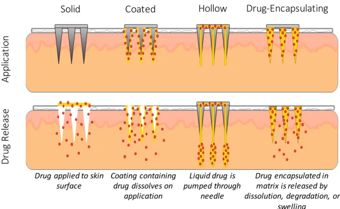
Microneedles can be divided into four classes based on their method of delivering therapeutics: (1) solid, (2) hollow, (3) coated, and (4) drug-encapsulating (Figure 1.2).4,13,26,31 Solid microneedles are applied to the skin, then removed. The area where the microneedles were applied is then covered with a therapeutic formulation, which diffuses through the channels created by the microneedles.4,26 Hollow microneedles contain open bores through the center of the needles, through which liquid formulations can be pumped.4,26 Coated microneedles have a drug formulation coated on the surface of the microneedles. Upon insertion into skin, the coating dissolves, releasing the drug in the skin.4,26 Drug-encapsulating microneedles are composed of dissolvable, degradable, or swellable materials with the therapeutic encapsulated within the microneedle matrix. When inserted into skin, the drug is released from the microneedle in a controlled manner dependent on the microneedle composition.4,13,31
7
Figure 1.2 Microneedle Classes. Application and drug release method of solid, coated, hollow, and drug-encapsulating microneedles. Figure adapted from reference 12.
Solid microneedles were the first type of microneedles developed and are intended to increase the permeability of topically-applied substances.32 The topically-applied drug can be formulated to release in a controlled manner over an extended period of time.13,18 Solid
microneedles are not limited in the quantity of therapeutic they can be used to deliver, but their reliance on passive diffusion results in poor control over dosing.13 Additionally, the two-step application process required with solid microneedles has the potential to interfere with patient compliance.4
Hollow microneedles are most similar to traditional hypodermic needles and function in the same manner, where a drug solution is allowed to passively diffuse or is pumped through the needles. The rate and amount of drug administered to the skin can be more easily controlled than with solid microneedles and is less limited than with coated or drug-encapsulating
Solid Coated Hollow Drug-Encapsulating
Ap pl ic at io n Dr ug R el ea se
Drug applied to skin
surface Coating containing drug dissolves on
application
Drug encapsulated in matrix is released by dissolution, degradation, or
swelling Liquid drug is
pumped through needle
8
microneedles.12,13,25 However, the hollow microneedles are more complex than other
microneedle classes, especially in cases where a pumping mechanism is involved, which could limit their accessibility to patients.13,25,33
Coated microneedles are coated with a dried layer of therapeutic which is released, usually within seconds to minutes, when inserted into skin.31,34 Coated microneedles are simple to use with a one-step application process and have more control over dosing than solid
microneedles.13 Therapeutic cargo has been shown to maintain stability on coated microneedles for extended periods of time when stored at room temperature, eliminating the need for cold chain storage of a liquid drug formulation.24,35,36 The major limitation of therapeutic delivery with coated microneedles is the limited quantity of therapeutic that can be coated on the
microneedles, typically less than 1 mg per patch, making coated microneedles only suitable for delivering potent molecules such as vaccines.25,34
Drug-encapsulating microneedles contain the drug within the microneedle, which is then released through dissolution, degradation, or swelling of the microneedles when inserted in skin.
These microneedles are often composed of biocompatible polymeric materials which are left in the skin in the case of dissolvable or degradable needles, eliminating the need for disposal of hazardous sharps waste.13,37,38 The application process for drug-encapsulating microneedles is simple, and dosing can be more controlled than with some other microneedle classes.13
Controlled release of encapsulated therapeutics is achievable with drug-encapsulating
microneedles, with release times of minutes to days or months depending on the microneedle material selection.31,38,39 However, drug-encapsulating microneedles are more limited in the quantity of therapeutic they can deliver than solid or hollow microneedles, and drug
9
encapsulation within the microneedle has the potential to alter the mechanical strength of the needle and the stability of encapsulated cargo.13,25
1.2.2 Microneedle Manufacturing
Although the concept of microneedles for drug delivery has existed since at least 1971, the capability to manufacture microneedles did not exist until the 1990s with the emergence of the fabrication techniques utilized in the microelectronics industry.40–42 The first microneedles for drug delivery were fabricated from silicon using lithography and reactive ion etching.32 Since this time, microneedles have been fabricated from a variety of materials, including silicon, metal, and polymers, using a wide range of techniques (Figure 1.3).
Figure 1.3 Silicon, Metal, and Polymer Microneedles. (A) Silicon microneedle produced using reactive ion etching. (B) Stainless steel microneedles fabricated using laser cutting. (C)
Carboxymethylcellulose microneedles fabricated using micromolding. Images reproduced with permission from references 32, 43, and 38, respectively.
1.2.2.1 Silicon and Metal Microneedle Fabrication
Silicon and metal are commonly used to make solid and hollow microneedles, which can be further modified with a therapeutic coating to produce coated microneedles. Silicon
microneedles can be directly fabricated using processes including reactive ion etching and wet etching.4,32,44–46 Both reactive ion etching and wet etching microneedle fabrication begin with the patterning of an etch mask on a silicon wafer using lithographic techniques.4,42 The silicon material is then etched using a plasma of reactive ions in the case of reactive ion etching or a liquid chemical such as potassium hydroxide in the case of wet etching to produce
(F igu r e 2). Mor eover , a ll bu t a few per cen t of t h e m icr o- n eedles r em a in ed fu lly in t a ct . On t h ose ver y few wh ich br oke, on ly t h e t op 5-10 µm wa s da m a ged. Micr on eedle a r r a ys cou ld a lso be r em oved wit h ou t difficu lt y or a d- dit ion a l da m a ge, a s well a s r ein ser t ed in t o skin m u lt iple t im es.
To qu a n t it a t ively a ssess t h e a bilit y of m icr on eedles t o in cr ea se t r a n sder m a l t r a n spor t , we m ea su r ed ca lcein
per m ea bilit y of h u m a n epider m is wit h a n d wit h ou t in - serted microneedle arrays. Calcein crosses skin very poorly u n der n or m a l cir cu m st a n ces a n d t h er efor e r epr esen t s a n especia lly difficu lt com pou n d t o deliver . As expect ed, pa ssive per m ea bilit y of ca lcein a cr oss u n a lt er ed skin wa s ver y low, in dica t in g t h a t t h e epider m is sa m ples wer e in t a ct (F igu r e 3). Mor eover , in con t r ol exper im en t s wh er e ba r e pieces of silicon wit h n o m icr on eedles et ch ed in t o t h em wer e pr essed a ga in st t h e skin , skin per m ea bilit y wa s n ot a ffect ed (da t a n ot sh own ).
In ser t ion of m icr on eedles in t o skin wa s ca pa ble of dr a m a t ica lly in cr ea sin g per m ea bilit y t o ca lcein (F igu r e 3).
Wh en m icr on eedles wer e in ser t ed a n d left em bedded in t h e skin , ca lcein per m ea bilit y wa s in cr ea sed by m or e t h a n 1,000-fold. In ser t ion of m icr on eedles for 10 s, followed by t h eir r em ova l, yielded a n a lm ost 10000-fold in cr ea se.
F in a lly, in ser t ion of a m icr on eedle a r r a y for 1 h , followed by its removal, increased skin permeability by about 25000- fold. P er m ea bilit ies for skin wit h m icr on eedles in ser t ed a n d t h en r em oved a r e h igh er t h a n for skin wit h m icr o- n eedles r em a in in g em bedded pr oba bly beca u se t h e m icr o- needles themselves or the silicon plate supporting the array m a y block a ccess t o t h e m icr oscopic h oles cr ea t ed in t h e skin . Ligh t m icr oscopy sh owed t h a t t h e h oles wh ich remained in the skin after microneedles were removed were a ppr oxim a t ely 1 µm in size (da t a n ot sh own ).
In cr ea sed skin per m ea bilit y a ppea r ed t o occu r r a pidly a ft er m icr on eedle in ser t ion a n d t o be m a in t a in ed for h ou r s in vit r o. Skin per m ea bilit y m ea su r em en t s wer e m a de on ce ever y h ou r . E leva t ed per m ea bilit y wa s a lwa ys seen du r in g t h e fir st h ou r a ft er m icr on eedle in ser t ion a n d r em a in ed a t a ppr oxim a t ely t h e sa m e level for a s m u ch a s 5 h (da t a n ot sh own ); lon ger exper im en t s wer e n ot per for m ed. Alt h ou gh r ever sibilit y wa s n ot seen , a n d wou ld n ot be expect ed in vit r o, h oles cr ea t ed by m icr on eedles in vivo a r e likely t o r esea l, a lt h ou gh t h e kin et ics of r esea lin g a r e pr esen t ly u n kn own .
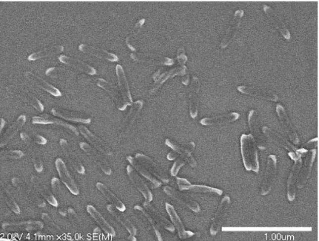
To su pplem en t in vit r o exper im en t s wh ich sh owed t h a t skin per m ea bilit y ca n be sign ifica n t ly in cr ea sed by m icr o- n eedles, pr elim in a r y r esu lt s wer e obt a in ed fr om st u dies wit h h u m a n volu n t eer s, for wh ich in for m ed con sen t a n d IRB a ppr ova l h a ve been secu r ed. Th ey in dica t ed t h a t Figure 1sScanning electron micrographs of microneedles made by the
reactive ion etching technique. (a) A section of a 20 by 20 array of microneedles. (b) Close-up viewof a microneedle tip. Microneedles are uniform in size and sharp at their tips, which is important for easy insertion to a desired depth in skin.
Figure 2sMicroneedle tips inserted across epidermis. An array of microneedles was inserted into the stratumcorneumside of human epidermis. The underside of the epidermis is shown, indicating that the microneedles penetrated across the tissue and that the tips were not damaged. Arrows indicate some of the microneedle tips.
Figure 3sPermeability of human skin treated with different microneedle protocols in vitro. Increases of 3 to 4 orders of magnitude were observed for microneedles (1) inserted and left in skin, (2) inserted for 10 s and then removed, and (3) inserted for 1 h and then removed. Such large increases in skin permeability have the potential to significantly increase the number and types of drugs which can be delivered across the skin. Each data point represents the average of 7 to 9 experiments. Standard deviation bars are shown.
924 / Journal of Pharmaceutical Sciences Vol. 87, No. 8, August 1998
A B C
10
microneedles.32,44 Metal microneedles composed of materials including stainless steel and titanium can also be fabricated using the wet etch process or by using laser cutting to fabricate microneedles out of metal sheets.4,34,47,48
Silicon and metal microneedles have several limitations due to the fabrication techniques used to make them and due to the properties of the materials. The etching techniques used to generate silicon and metal microneedles are fairly complex, require specialized training, and can be time consuming.12,13,49 Additionally, only microneedles of limited geometries can be produced using these techniques. The fabrication of microneedles using etching techniques is generally limited to microneedles less than 500 µm in height, and the aspect ratio of the needles cannot be easily controlled.4,32,44,50 Wet etching also necessitates large interneedle spacing, which can limit the microneedle density on the array.4,44 As silicon and metal are not biodegradable, and silicon is not biocompatible, adverse effects could occur if microneedles of these materials were to fragment in the skin.4,26,37,38
1.2.2.2 Polymer Microneedle Fabrication
As a result of the limitations associated with the fabrication and use of silicon and metal microneedles, polymer microneedles have become increasingly popular. A range of polymeric materials, including poly(lactide-co-glycolide) (PLGA),39,51,52 poly(vinyl pyrrolidone) (PVP),53–
55 poly(methylvinylether-co-maleic anhydride) (PMVE/MA),56,57 poly(acrylic acid) (PAA),58 carboxymethylcellulose (CMC),38,59,60 hyaluronic acid,61–63 silk fibronin,64–66 and others, have been utilized to fabricate microneedles. These materials are biocompatible and dissolve or degrade after insertion into skin, minimizing the risk of adverse immunological reactions compared to silicon and metal microneedles.4
11
A number of fabrication techniques have been utilized to manufacture polymeric
microneedles, including drawing lithography,67 droplet-born air blowing,68 and electrodrawing.69 However, the most common polymer microneedle fabrication technique is micromolding (Figure 1.4). In the micromolding process, a microneedle master is fabricated from metal or silicon, typically using one of the previously described fabrication techniques for metal and silicon microneedles or an alternative approach such as multidirectional UV lithography.39,51,70,71 An inverse mold of the microneedle master is then created using a non-wetting polymer, frequently poly(dimethylsiloxane) (PDMS).38,51,53,60 Finally, the PDMS mold is filled with the desired polymeric microneedle material and any cargo of interest, often by applying vacuum and centrifugal force.38,51,53,60 After the mold is filled and the microneedle has solidified, the mold is removed, leaving the final microneedle patch.
Figure 1.4 Microneedle Micromolding Process. An inverse microneedle mold is fabricated from a microneedle master. The mold is then filled with the microneedle material, which is solidified and removed from the mold to produce the microneedle patch.
Micromolding is a useful method for producing polymeric microneedles, but the process has a few limitations. The fabrication of microneedles using this technique is often time
consuming, with hours to days necessary for filling the mold alone and additional time required to generate the microneedle masters and PDMS molds.38,66 The techniques used to fill the microneedle molds, including vacuum and centrifugation, are often done in a batch-to-batch
Microneedle Master Microneedle Mold
Microneedle Patch
12
manner that would be difficult to scale up in an industrial setting.22,72 If polymer microneedles are to be successfully commercialized for vaccine and therapeutic delivery applications, improved manufacturing techniques are necessary.
1.3 Particle Replication in Non-Wetting Templates (PRINT) Microneedles To overcome some of the limitations associated with polymeric microneedle
manufacturing, the technology Particle Replication in Non-wetting Templates (PRINT) has been applied to microneedle fabrication. PRINT was originally developed as a top-down nano- and microparticle fabrication technique, in which non-wetting perfluoropolyether (PFPE) molds are used to precisely shape monodisperse particles with a range of compositions, sizes, shapes, and surface functionalities.73–75 PRINT has been utilized to fabricate dissolvable square pyramidal PVP microneedles, with fabrication times of less than 5 minutes per patch (Figure 1.5).72
Figure 1.5 PVP PRINT Microneedles. Brightfield images of PRINT microneedles loaded with the small molecule dye rhodamine. Scale bars measure 200 µm in (A) and 1 cm in (B,C). Figure reproduced with permission from reference 72.
A
B C
13
A schematic of the PRINT microneedle fabrication process is shown in Figure 1.6. A pre- microneedle solution containing PVP and any cargo of interest is drop-cast to form solid pre- microneedle films. The pre-microneedle film is then placed on a PFPE microneedle mold, which is passed through a heated laminator to melt the film and fill the mold. The filled mold is then placed on flexible, water-soluble backing layer composed of a poly(vinyl pyrrolidone) / poly(vinyl acetate) blend and once again passed through the heated laminator. The mold is removed from the microneedles, leaving a fully water-soluble microneedle patch. The PRINT microneedle fabrication process is highly scalable and can be used to make microneedle patches of any size quickly and efficiently.72 PRINT microneedles have been shown to effectively deliver an encapsulated small molecule drug surrogate to skin ex vivo, suggesting they hold promise for delivering therapeutic cargo transdermally.72
Figure 1.6 PRINT Microneedle Fabrication Process. A solid pre-microneedle film (red) composed of PVP is mated to a microneedle mold (green), then passed through a heated nip to fill the mold. A flexible backing layer (yellow) is then mated to the filled microneedle mold and passed through the heated nip. The microneedle mold is removed, leaving a microneedle array on a flexible backing layer. Figure reproduced with permission from reference 72.
14
1.4 Additive Manufacturing for the Fabrication of Microneedles
Additive manufacturing, or three-dimensional (3D) printing, has emerged in recent years as a microneedle manufacturing technology with the potential to overcome some of the
limitations associated with traditional methods of making microneedles. Most current microneedle manufacturing techniques require long lead times and involve many time- consuming fabrication steps, particularly for making molded polymeric microneedles.38,66 Additionally, these fabrication methods are only able to produce microneedles of limited geometries.4,32,44,50,56 As microneedle geometry, including factors such as needle height,76–79 needle density,76,80 shape,81,82 and tip radius,83,84 has been demonstrated to influence the efficacy of microneedles in delivering therapeutics, the ability to rapidly alter microneedle geometry in a controlled manner would be valuable in designing the optimal microneedle array for specific therapeutic applications.
Using additive manufacturing, computationally designed microneedles can be directly fabricated in a single step, with minimal lead time and without the geometric limitations imposed by other manufacturing techniques.50 In additive manufacturing, the desired object is
computationally designed using 3D modeling software to generate a computer-aided design (CAD) file of the object.85 This CAD file is then sliced into cross-sections, which are fabricated one layer at a time to produce the object.85 Additive manufacturing includes such techniques as selective laser sintering, fused deposition modeling, and stereolithography.86 Stereolithography (SLA), which uses photopolymerization to create objects layer-by-layer from a liquid resin, is the most commonly utilized additive manufacturing method for the production of microneedles with drug delivery applications.50,86–89
15
Microstereolithography has been used to manufacture microneedles composed of the biodegradable photopolymerizable polymer poly(propylene fumarate) (PPF) with a layer-by- layer fabrication process (Figure 1.7A).87,88 Using a digital micromirror device (DMD), UV light was projected in the shape of the appropriate microneedle cross-sectional layer into a vat of photopolymerizable liquid resin, which contained the polymers PPF and diethylfumarate, a photoinitiator, and the chemotherapy drug dacarbazine.87 Once one layer had cured, the stage which it was adhered to was moved further down into the vat of resin, and the process was repeated for the next layer.87 Microneedles fabricated in this manner were 1000 µm tall with a 20 µm layer thickness and had a fabrication time of around 1 hour per patch.87 Dacarbazine
encapsulated within the PPF microneedles was found to slowly release over the course of 35 days in solution.87
Figure 1.7 Microneedles Fabricated with Additive Manufacturing. (A) PPF microneedles produced using microstereolithography. (B) Ormocer microneedles produced using two-photon polymerization. Images reproduced with permission from references 87 and 90, respectively.
Another stereolithography technique used to fabricate microneedles is two-photon polymerization (2PP) (Figure 1.7B). In 2PP, an ultrashort-pulsed laser is traced in 3 dimensions through a photopolymerizable liquid resin.89,91 The laser excites the photoinitiator in the resin through the simultaneous absorption of two photons, which initiates free radical
B A
16
photopolymerization of the resin.89,91 With 2PP, very small volumes of resin can be selectively photopolymerized to produce high resolution features of less than 100 nm, although there is a trade-off of longer production times for higher resolution features.50 The 2PP process has been utilized to fabricate microneedles of a range of geometries and compositions including Ormocer, a photopolymerizable organically modified ceramic material, and poly(ethylene glycol)
dimethacrylate.92,93 However, the 2PP microneedle fabrication process is slow, especially for high resolution microneedles, which has limited its utility for direct microneedle fabrication.90 Instead, 2PP microneedles are often utilized as microneedle masters, which are used to manufacture polymeric microneedles with further micromolding steps.50,90,93,94
1.4.1 Continuous Liquid Interface Production (CLIP)
While microstereolithography and 2PP have been used to successfully fabricate
microneedles, the layer-by-layer nature of these techniques results in slow fabrication times, with a trade-off between microneedle resolution and manufacturing efficiency.50 In traditional SLA, each layer of the object is cured, then must be repositioned before the next layer is fabricated.
While the use of thinner layers results in higher resolution of the object, the number of time- consuming repositioning steps also increases, leading to longer production times. Continuous Liquid Interface Production (CLIP) is a continuous, rather than layer-by-layer, additive
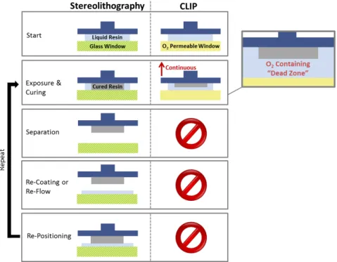
manufacturing technique that can overcome some of the limitations associated with traditional SLA microneedle production.95,96 The CLIP process works by shining UV light through an oxygen-permeable window into a vat of photopolymerizable liquid resin to selectively cure it.
Above the window, an oxygen-inhibited “dead zone” of unpolymerized liquid resin is maintained, which allows for continuous fabrication with no need for repositioning as in
17
traditional SLA (Figure 1.8).95 Using CLIP, high resolution structures can be fabricated with no trade-off between resolution and fabrication time (Figure 1.9).95,97
Figure 1.8 Differences between Stereolithography and CLIP. In traditional stereolithography, each layer is cured, then separated and repositioned. CLIP eliminates the need for separation and repositioning due to the presence of the oxygen-inhibited dead zone, allowing for continuous production. Figure reproduced from reference 96.
Figure 1.9 Layer Thickness vs Fabrication Time Trade-Off. In traditional layer-by-layer additive manufacturing techniques, increasing resolution by decreasing the layer thickness leads to longer fabrication times. With CLIP, there is no trade-off between resolution and fabrication time. Figure reproduced from reference 96.
18
The CLIP process has previously been applied to the fabrication of polymeric
microneedles.96 An overview of the CLIP microneedle manufacturing process is shown in Figure 1.10. Microneedles are computationally designed using modeling software to generate a CAD file of the microneedle patch. The microneedle CAD file is then sliced into cross-sections, which are projected in succession using UV light off a digital light projection (DLP) chip through a UV and oxygen-permeable window into a pool of photopolymerizable liquid resin. Above the
oxygen-inhibited dead zone, the area where UV light hits the resin is selectively polymerized on the build elevator, which moves upward as cross-sections are projected for continuous
production of the microneedle patch. Using CLIP, high resolution microneedles of a range of geometries can be fabricated in a matter of minutes (Figure 1.11). This ability to rapidly alter microneedle design parameters could be a valuable tool in fabricating microneedles for drug delivery applications.
Figure 1.10 CLIP Microneedle Fabrication Process. Microneedles CAD files are
computationally sliced into cross-sections, which are then projected using UV light into a pool of photopolymerizable liquid resin, selectively curing it. An oxygen-permeable window below the resin vat results in a dead zone with no polymerization, which enables continuous production as the build elevator moves upward. Figure adapted from reference 96.
CAD file of object
1
Object sliced into cross-sections
2
DLP Chip
Dead Zone Liquid Resin Build Elevator
Continuous Movement
Light Source UV Light
O2Permeable Window
3
19
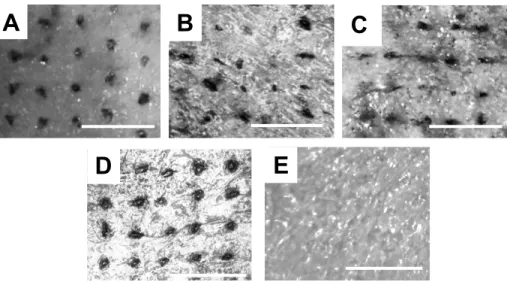
Figure 1.11 CLIP Microneedle Geometries. Trimethylolpropane triacrylate (TMPTA) microneedles produced using CLIP. Microneedle (A) aspect ratio, (B,C) spacing, (D,F) shape, and (E) height can be controlled. Scale bars measure 500 µm. Figure reproduced from reference 96.
1.5 Thesis Overview
Microneedles show promise for enhancing the transdermal delivery of a range of therapeutics, but current microneedle manufacturing processes are time-consuming, difficult to scale up, and have limited control over microneedle design parameters. In this work, we utilize two novel microneedle manufacturing techniques, PRINT and CLIP, to fabricate polymeric microneedles for drug delivery applications. In Chapter 2, the ability to fabricate dissolvable PRINT microneedles loaded with a range of model and therapeutic cargoes, including small molecules, proteins, and nanoparticles, is demonstrated, and the transdermal permeation of these microneedle-delivered cargoes is assessed ex vivo. In Chapter 3, we demonstrate the ability to fabricate CLIP microneedles composed of a library of drug-releasing materials and investigate their utility for delivering encapsulated small molecule and protein cargo. In Chapter 4, a method for coating CLIP microneedles with cargo is established, and the delivery of protein cargo using coated CLIP microneedles is investigated ex vivo. A summary and recommendations for future work are presented in Chapter 5.
20 REFERENCES
1. Prausnitz, M. & Langer, R. Transdermal drug delivery. Nat. Biotechnol 26, 1261–1268 (2008).
2. Prausnitz, M. R., Mitragotri, S. & Langer, R. Current status and future potential of transdermal drug delivery. Nat Rev Drug Discov 3, 115–124 (2004).
3. Prausnitz, M. R. et al. in Dermatology 2065–2073 (2012). doi:10.1016/B978-0-7234- 3571-6.00124-X
4. Donnelly, R. F., Singh, T. R. R., Morrow, D. & Woolfson, A. D. Microneedle-mediated Transdermal and Intradermal Drug Delivery. (John Wiley & Sons, 2012).
5. Paudel, K. S. et al. Challenges and opportunities in dermal/transdermal delivery. Ther.
Deliv. 1, 109–131 (2010).
6. Naik, A., Kalia, Y. N. & Guy, R. H. Transdermal drug delivery: Overcoming the skin’s barrier function. Pharm. Sci. Technol. Today 3, 318–326 (2000).
7. Moffatt, K., Wang, Y., Raj Singh, T. R. & Donnelly, R. F. Microneedles for enhanced transdermal and intraocular drug delivery. Curr. Opin. Pharmacol. 36, 14–21 (2017).
8. Pastore, M. N., Kalia, Y. N., Horstmann, M. & Roberts, M. S. Transdermal patches:
History, development and pharmacology. Br. J. Pharmacol. 172, 2179–2209 (2015).
9. Benson, H. A. E. & Watkinson, A. C. Topical and Transdermal Drug Delivery Principles and Practice. (John Wiley & Sons, 2011).
10. Menon, G. K. New insights into skin structure: Scratching the surface. Adv. Drug Deliv.
Rev. 54, (2002).
11. Chu, D. H. in Fitzpatrick’s Dermatology in General Medicine 57–92 (2012).
12. Kim, Y.-C., Park, J.-H. & Prausnitz, M. R. Microneedles for drug and vaccine delivery.
Adv. Drug Deliv. Rev. 64, 1547–1568 (2012).
13. Maaden, K. Van Der, Jiskoot, W. & Bouwstra, J. Microneedle technologies for (trans)dermal drug and vaccine delivery. J. Control. Release 161, 645–655 (2012).
14. Alkilani, A. Z., McCrudden, M. T. C. & Donnelly, R. F. Transdermal drug delivery:
Innovative pharmaceutical developments based on disruption of the barrier properties of the stratum corneum. Pharmaceutics 7, 438–470 (2015).
15. Lane, M. E. Skin penetration enhancers. Int. J. Pharm. 447, 12–21 (2013).
16. Karande, P. & Mitragotri, S. Enhancement of transdermal drug delivery via synergistic action of chemicals. Biochim. Biophys. Acta - Biomembr. 1788, 2362–2373 (2009).
21
17. Karande, P., Jain, A., Ergun, K., Kispersky, V. & Mitragotri, S. Design principles of chemical penetration enhancers for transdermal drug delivery. Proc. Natl. Acad. Sci. U. S.
A. 102, 4688–4693 (2005).
18. Prausnitz, M. R. Engineering Microneedle Patches for Vaccination and Drug Delivery to Skin. Annu. Rev. Chem. Biomol. Eng. 8, 177–200 (2017).
19. Harvey, A. J. et al. Microneedle-based intradermal delivery enables rapid lymphatic uptake and distribution of protein drugs. Pharm. Res. 28, 107–116 (2011).
20. Kim, Y. C. & Prausnitz, M. R. Enabling skin vaccination using new delivery technologies.
Drug Deliv. Transl. Res. 1, 7–12 (2011).
21. Kupper, T. S. & Fuhlbrigge, R. C. Immune surveillance in the skin: mechanisms and clinical consequences. Nat. Rev. Immunol. 4, 211–222 (2004).
22. Leone, M., Mönkäre, J., Bouwstra, J. A. & Kersten, G. Dissolving Microneedle Patches for Dermal Vaccination. Pharm. Res. 1–18 (2017). doi:10.1007/s11095-017-2223-2 23. Quan, F.-S., Kim, Y.-C., Compans, R. W., Prausnitz, M. R. & Kang, S.-M. Dose sparing
enabled by skin immunization with influenza virus-like particle vaccine using microneedles. J. Control. Release 147, 326–332 (2010).
24. Chen, X. et al. Improving the reach of vaccines to low-resource regions, with a needle- free vaccine delivery device and long-term thermostabilization. J. Control. Release 152, 349–355 (2011).
25. Tuan-Mahmood, T.-M. et al. Microneedles for intradermal and transdermal drug delivery.
Eur. J. Pharm. Sci. 50, 623–637 (2013).
26. Prausnitz, M. R. Microneedles for transdermal drug delivery. Adv. Drug Deliv. Rev. 56, 581–587 (2004).
27. Gill, H. S., Denson, D. D., Burris, B. A. & Prausnitz, M. R. Effect of microneedle design on pain in human volunteers. Clin. J. Pain 24, 585–94 (2008).
28. Haq, M. I. et al. Clinical administration of microneedles: skin puncture, pain and sensation. Biomed. Microdevices 11, 35–47 (2009).
29. Hamilton, J. G. Needle phobia: a neglected diagnosis. J. Fam. Pract. 41, 169–176 (1995).
30. Norman, J. J. et al. Microneedle patches: Usability and acceptability for self-vaccination against influenza. Vaccine 32, 1856–1862 (2014).
31. Escobar-Chávez, J. J. et al. Microneedles : A Valuable Physical Enhancer to Increase Transdermal Drug Delivery. J. Clin. Pharmacol. 51, 964–977 (2011).