• No results found

PERORMANCE ANALYSIS OF FWM ON AN OPTICAL WDM SYSTEM USING DIFFERENT MODULATION TECHNIQUE

N/A
N/A
Protected

Academic year: 2020

Share "PERORMANCE ANALYSIS OF FWM ON AN OPTICAL WDM SYSTEM USING DIFFERENT MODULATION TECHNIQUE"

Copied!
7
0
0

Loading.... (view fulltext now)

Full text

(1)

PERORMANCE ANALYSIS OF FWM ON AN OPTICAL WDM SYSTEM USING DIFFERENT MODULATION TECHNIQUE

BANDANA MALLICK*1, SAURAV ASOPA2, SALONI JAIN3, NEHA SUMAN4

*1.Asst Professor, Department of Electronics & Communication GIET, Gunupur, Odisha, india 2,34.Student of Electronics & Communication engineering,GIET,Gunupur,Odisha,India

Abstract

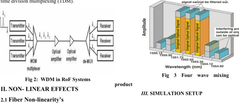
The trend toward higher bit rates in light wave communication has interest in dispersion-shifted fibre to minimize dispersion penalties. At the same time optical amplifiers have increased interest in wavelength multiplexing. These two methods of increasing system capacity if used together can result in severe degradation due to fibre non-linearity. So the effect of dispersion, input power and fibre length on the bit error rate and, Quality Factor and resultant power are investigated in our study. The performances are analyzed in terms of transmitted channel power, Eye Diagram and bit error rate (BER) of the system. The performance of wavelength division multiplexing (WDM) in radio over fiber (RoF) systems is found to be intensely influenced by nonlinearity characteristics within the fiber. In this paper, the performance of WDM network is analyzed using external modulation schemes under FWM nonlinearity effect with the help of eye diagram.

Keywords

fiber optics, optical fiber dispersion, Four Wave Mixing (FWM), Radio over Fiber (RoF), DPSK, , QPSK,OQPSK

1. INTRODUCTION

Optical fibre communication provides a very large bandwidth (50 THz) and it becomes the most modern means of communication. Fiber-optic communication systems have revolutionized the telecommunications industry and played a major role in the advent of the information age. RoF is a technology used to distribute RF signals over analog optical links. The main objective of this project is to evaluate the FWM in different modulation technique for RoF technology, in order to calculate the impairments associated with long-distance high-bit rate optical fiber communication systems. In order to achieve the objective, optisystem software will be used respectively in the numerical simulation and the

Fig-1 Block diagram of fiber optic communication

WDM are passive devices that combine light

signals with different wavelengths, coming from

different fibers, onto a single fiber. They include

dense wavelength division multiplexers (DWDM),

devices that use optical (analog) multiplexing

techniques to increase the carrying capacity of fiber

(2)

time division multiplexing (TDM).

Fig 2: WDM in RoF Systems

II. NON- LINEAR EFFECTS

2.1 Fiber Non-linearity’s

The nonlinear effects in fibers can be broadly classified into two categories: stimulated scattering effects and Kerr effects. The scattering effects are due to the interaction of light waves with molecular or sound waves in fiber. The scattering effects include Brillouin scattering (SBS) and Stimulated Raman Scattering (SRS) .

2.1.1 Four wave mixing

Four-wave mixing is a non- linear effect arising from a third-order optical nonlinearity, as is described with a χ

(3)

coefficient. It can occur if at least two different frequency components propagate together in a nonlinear medium such as an optical fibre. This effect is generated by the third order distortion that creates third order harmonics. As shown in Figure these cross products interfere with the original wavelength and cause the mixing. In fact, these spurious signals fall right on the original wavelength which results in difficulty in filtering them out..

Fig 3 Four wave mixing product

III. SIMULATION SETUP

Our simulation is performed and analyzed using OptiSystem 14.0 software . In this paper, the architecture is analyzed to reduce the effect of FWM in WDM system which can be done by using:

A) Direct Modulation B) External Modulation 3.1 Direct Modulation

In this technique the direct current which is supplying the light source is modulated. This is done by making small changes to biased current of the laser.

In this the value of the biased current is maintained below the threshold value. It is done in order to make the laser on and off according to the situation. The wavelength of the circuit depends upon the type of modulation technique used.

Fig 4Simulation model using PM Modulator

(3)

3.2 Indirect modulation :

System degradations do not affect the indirect modulation. In this an external modulator is used.

Lithium niobate is present in the crystal form. Its refractive index can be controlled easily by controlling the electric field. As the refractive index will come under control, the incoming signals will also come under control.

3.2.1 QPSK Modulation

Figure 5 shows the simulation setup in optisystem software for two channels transmitted using QPSK modulation. An electrical QPSK modulator is used to generate a QPSK sequence which is then further modulated using mach-zender modulator. The two modulated inputs are then multiplexed and sent over fiber of length 25 km. The output is analyzed using optical spectrum analyzer and WDM analyzer

.

Fig 5: simulation model using QPSK

3.2.2 DPSK Modulation

Figure 6 shows the simulation setup in Optisystem software for two channels transmitted using DPSK modulation

.

Fig 6 : Simulation model using DPSK 3.2.3 OQPSK MODULATION

Fig 7: Simulation model using OQPSK

IV. RESULT & DISCUSSION

The numerical simulation is simulated accordingly as mentioned in the previous chapter using different modulation techniques.

4.1.

QPSK Modulation

The result obtained from the simulation with QPSK modulation is shown in Figure 8(a).

The power of the each FWM sideband is

(4)

Fig 8. Optical spectrum at the input using QPSK modulation.

Fig 9. Optical spectrum at the output using QPSK modulation

Fig 10. Eye Diagram of QPSK

4.2 DPSK Modulator

In this simulation two CW lasers were used as signals sources, the frequencies were set at 1550 nm.

The input signals have propagated through 50 km of nonlinear fiber.

Fig 11.Optical spectrum at the input

Fig 12.Optical spectrum at the output

Fig13 Optical spectrum at the input of the fiber

(5)

4.3 OQPSK Modulator

Fig15 Eye Diagram of OQPSK without Bessel filter

Fig 14Optical spectrum at the output of the fiber

Fig16 Eye Diagram of OQPSK with Bessel filter

V .CONCLUSION

Radio over fiber (RoF) network accompanied with wavelength division multiplexing WDM) can provide a simple topology, easier network management, and an increased capacity by allocating different wavelengths to individual remote nodes. The performance of WDM networks is strongly influenced by nonlinearity characteristic inside the fiber. Therefore the nonlinearity effects of fiber optics pose additional limitation in WDM systems.The numerical simulation results obtained have shown the spectral characteristics of the FWM in WDM for RoF.

VI.REFERENCES

[1] Jameel Ahmed, Ashiq Hussain, M.Y. Siyal, Habibullah Manzoor, Abdullah Masooda,

―Parametric analysis of four wave mixing in DWDM systemsǁ, Optik, vol. no (125), pp.1853–

1859, 2014.

[2] Sikha Moni Bhuyan, Prof. Sarwar Raeen

―Extending the Reach of DWDM ROF-PON Link with Optimization of Four Wave Mixing Effect with Comparative Analysis of Different Modulation Formatsǁ,International Journal of Modern Engineering and Research Technology, Volume 2, Issue 2, April 2015

[3] A. V. Yulin, D. V., and P. St. J. Russell

“Four-wave mixing of linear waves and

solitons in fibers with higher-order dispersion”

(6)

Journal of lightwave technology, 29 (3) (2004) 950-955.

[4] Remigius Zengerle, “Modeling of Nonlinear Phenomena in Optical Multi- channel Trasmission system” Master thesis, University of Kaiserslautern, 2005.

[5] Ooi Sock, “Four Wave Mixing Nonlinearity Effect in Wavelength Division Multiplexing System for Radio Over Fiber.” Bachelor thesis, University Technology Malaysia, 2007.

[6] Manpreet Kaur10,Himali Sarangal ―Analysis on Dispersion Compensation with Dispersion Compensation Fiber (DCF)ǁ (SSRG-IJECE) – volume 2 issue 2 Feb 2015.

[7] Bijayananda Patnaik and Prasant Kumar Sahu

―Optimization of Four Wave Mixing Effect in

Radio-over-Fiber for a 32-Channel 40-GBPS DWDM

Systemǁ 2010 International Symposium on Electronic

System Design (ISED), pp.119-124, December 2010

.

(7)

Figure

Fig 3 Four wave mixing product
Figure 5 shows the simulation setup in optisystem software for two channels transmitted using QPSK modulation
Fig 8. Optical spectrum at the input using QPSK modulation.
Fig 14Optical spectrum at the output of the fiber

References

Related documents