Optimization of the Cutting Fluids and Parameters
Using Taguchi and ANOVA in Milling
E. Kuram, B. T. Simsek, B. Ozcelik, E. Demirbas, and S. Askin
Abstract- In this study, two different vegetable based cutting
fluids developed from refined canola and sunflower oil and a commercial type semi-synthetic cutting fluid were carried out to determine optimum conditions for tool wear and forces during milling of AISI 304 austenitic stainless steel. Taguchi
L9 (34) orthogonal array was used for the experiment plan.
Cutting speed, feed rate, depth of cut and types of cutting fluids were considered as machining parameters. Mathematical models for cutting parameters and cutting fluids were obtained from regression analyses to predict values of tool wear and forces. S/N ratio and ANOVA analyses were also performed to obtain for significant parameters influencing tool wear and forces.
Index Terms- Cutting force, Milling, Tool wear, Vegetable
based cutting fluids.
I. INTRODUCTION
The machinability of AISI 304 stainless steel is difficult since it has high strength, low thermal conductivity, high ductility and high work hardening tendency. Poor surface finish, high force and high tool wear are also observed when machining this material. Cutting fluids are used to eliminate these detrimental effects of heat and friction, improve surface finish, provide lubrication between chip-tool interface and flushing away chips from machining of AISI 304. Today a wide variety of cutting fluids are commercially available namely, straight oils, soluble oils, synthetic and semi synthetic fluids. However, their use is today being questioned for renewable, environmental, health and readily biodegradable.
Many investigations are in progress to develop new bio based cutting fluids from various vegetable oils in the world. Studies about the use of vegetable based cutting fluids (VBCFs) on different mechanical processes have been focused on drilling [1-7], turning [7,8], tapping [6,7,9] and reaming [6,7,9,10]. In these studies tool wear [1,8], tool
Manuscript received February 16, 2010. This work was supported in part by TUBITAK (project no: 107M164).
E. Kuramis with the Gebze Institute of Technology, Department of Mechanical Engineering, 41400 Gebze-Kocaeli, Turkey (e-mail: [email protected]).
B. T. Simsek is with the Gebze Institute of Technology, Department of Mechanical Engineering, 41400 Gebze-Kocaeli, Turkey (e-mail: [email protected]).
B. Ozcelik is with the Gebze Institute of Technology, Department of Mechanical Engineering, 41400 Gebze-Kocaeli, Turkey (e-mail: [email protected]).
E. Demirbas is with the Gebze Institute of Technology, Department of Chemistry, 41400 GebzKocaeli, Turkey (phone: +90 262 6053069; e-mail: [email protected]).
S. Askin is with the Gebze Institute of Technology, Department of Chemistry, 41400 Gebze-Kocaeli, Turkey (e-mail: [email protected]).
life [7,9], cutting force [1,2,4,6,7,10], torque [10] and surface roughness [2-5, 8-10] are taken into consideration.But, no published works are available for milling with VBCFs. Some published studies for the milling with other than VBCFs were as follows: Vieira et al. [11] investigated performance of mineral, semi-synthetic and synthetic cutting fluids when face milling of AISI 8640 steel with coated cemented carbide tools in terms of tool life, power consumption and surface roughness. Dry machining was also performed for comparison purpose. The best tool life was recorded when milling dry, followed, in a decreasing order by the application of synthetic and semi-synthetic cutting fluids. Dry machining also gave better surface finish than machining in the presence of cutting fluid. Abou-El-Hossein [12] studied the efficiency of cutting fluids when end milling of AISI 304 stainless steel. Tool life and tool wear mechanisms with wet machining were compared to dry cutting. Results showed that cutting fluid application was efficient at low cutting speeds. Dominant wear mechanisms in dry machining were built-up edge and nose wear, while in wet machining dominant wear mechanisms were notch wear and cutting edge grooving.
Many problems are also identified with the use of metal cutting fluids (MCFs), such as health and environment hazards. An environmentally MCF has to be biodegradable, not to be toxic and produce low emissions when in use. This work presents new MCF formulations able to meet both the performance and environmental requirements. The proposed fluids are based on refined vegetable oils (sunflower and canola) as base oil mixed with a mixture of emulsifiers by different ratio in water for milling with AISI 304 austenitic stainless steel. In this study, two different VBCFs and a commercial type semi-synthetic cutting fluid were used to optimize cutting parameters for tool wear and forces during milling of AISI 304. Significant parameters affecting tool wear and forces were determined from ANOVA.
II. EXPERIMENTAL SETUP
A. Vegetable Based Cutting Fluid
In metalworking operations, the frictional resistance can be reduced by adding a lubricant between the surfaces. Lubricants separate the sliding surfaces by forming a film, and thereby reduce the frictional resistance and wear.
TABLE 1
CHARACTERIZATION OF VEGETABLE BASED CUTTING FLUIDS Metal cutting fluid* pH
(Emulsion 8%)
Density (g/ml)
Viscosity 40 °C (mm2/sec)
Viscosity, 40 °C (mm2/sn)
(Emulsion 8%)
Flash point (°C)
Refractive index
SCF-II (8% EP) 8.92 0.96 91 4.1 217 1.4775
CCF-II (8% EP) 9.00 0.97 110 3.9 232 1.4770
CSSF 9.18 0.98 75 1.7 235 1.4825
* SCF-II (8% EP): sunflower cutting fluid with 8% EP additive; CCF-II (8% EP): canola cutting fluid with 8% EP additive; CSSF: Commercial semi-synthetic cutting fluid.
oil and a mixture of emulsifier (Tween 80 (9%)-Tween 85 (25%)). Other components may be added to the cutting fluid such as neutralization agents, corrosion and rust inhibitors, lubricating additives (EP, extreme pressure), biocides, fungicides and foam inhibitors. The additive concentrations used were below 10% w/w. Its appearance has to be monophasic and its dilution with water associated with gentle mixing must produce an oil-in-water emulsion. An emulsion is a dispersion of one immiscible liquid into another, through the use of a chemical reagent that reduces the interfacial tension between the two liquids to achieve stability. A short time of separation will restrict the use of the emulsion as a cutting fluid because lubrication capacity decreases with stability. The stability of the emulsion system depends on the size of the droplets produced during emulsion formation. In order to produce an emulsion with an average diameter of several hundred nanometers, a powerful homogenizer was used at a rotational speed of 10000 rpm for 10 min. After emulsification, the samples were kept at room temperature. Emulsion stability was judged by observing phase separation for 24 h. The optimum cutting fluid composition is evaluated from surface tension measurements using different concentration of emulsions (1-30%) which lead to determine value of critical micelle concentration (CMC). The stable oil-in-water emulsion was prepared close to and above their critical micelle concentrations (CMC). Water content in the cutting fluid varied depending on the source, but the cutting fluid in the present study contained 92% water. Characterization of vegetable based cutting fluids was shown in Table 1.
The cutting fluids were applied to the tool via two nozzles. The coolant flow rate (10 l/min for each nozzle) was held constant throughout the experiments.
B. Machining Conditions and Experimental Design In this study, cutting speed, feed rate, depth of cut and cutting fluids were considered as machining parameters. An L9 (34) Taguchi orthogonal array was
used as the experimental design. The parameters investigated and the levels were indicated in Table 2.
C. Workpiece Materials and Cutting Tools
AISI 304 austenitic stainless steel was used as a workpiece material. The dimension of workpiece was 165 mm x 104 mm x 30 mm. The workpieces from the same
batch were used in the experiments. The chemical composition of workpiece was given in Table 3.
TABLE II
MACHINING PARAMETERS AND THEIR LEVELS Level Cutting
speed (m/min)
Feed rate
(mm/rev) Depth of cut (mm)
Cutting fluids
1 150 0.20 0.2 SCF-II
2 175 0.25 0.3 CCF-II
3 200 0.30 0.4 CSSF
TABLE III
THE CHEMICAL COMPOSITION OF WORKPIECE MATERIAL
AISI 304 (%)
C Si Mn P S
0.0340 0.6400 1.8900 0.0410 0.0130
Cr Ni Mo Cu Co
18.7500 8.2300 0.3980 0.6900 0.1050 Fe
69.0000
The length of each cutting path was 1040 mm. Radial depth of cut (step over) was 10 mm. The milling experiments were carried out on a DECKEL MAHO DMU 60 P five axis CNC milling machine equipped with a maximum spindle speed of 12000 rpm and a 15 kW drive motor. A holder with two inserts (Iscar HM90 APKT 100304PDR IC908) was coupled to the shrink holder with a diameter of 16 mm. The milling process was interrupted after every experiment and value of the wear was measured.
D. Tool Wear Measurement
Flank wear was measured at 50x magnification using an optical microscope (NIKON SMZ800). Whenever a milling process was ended, two inserts used were replaced with a new one. The flank wear oftwo inserts were measured, and their values were averaged.
E. Force Measurement
TABLE IV
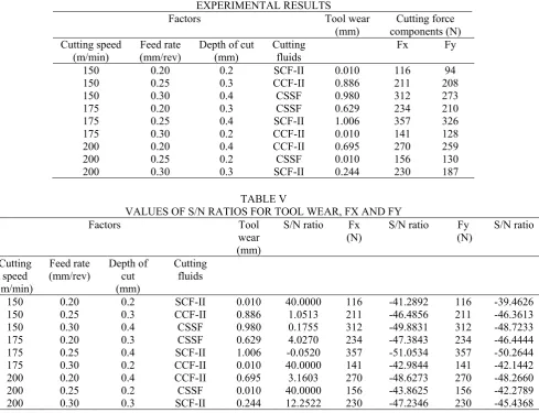
EXPERIMENTAL RESULTS
Factors Tool wear
(mm)
Cutting force components (N) Cutting speed
(m/min) (mm/rev) Feed rate Depth of cut (mm) Cutting fluids Fx Fy
150 0.20 0.2 SCF-II 0.010 116 94
150 0.25 0.3 CCF-II 0.886 211 208
150 0.30 0.4 CSSF 0.980 312 273
175 0.20 0.3 CSSF 0.629 234 210
175 0.25 0.4 SCF-II 1.006 357 326
175 0.30 0.2 CCF-II 0.010 141 128
200 0.20 0.4 CCF-II 0.695 270 259
200 0.25 0.2 CSSF 0.010 156 130
200 0.30 0.3 SCF-II 0.244 230 187
TABLE V
VALUES OF S/N RATIOS FOR TOOL WEAR, FX AND FY Factors Tool
wear (mm)
S/N ratio Fx
(N) S/N ratio (N) Fy S/N ratio
Cutting speed (m/min)
Feed rate
(mm/rev) Depth of cut (mm)
Cutting fluids
150 0.20 0.2 SCF-II 0.010 40.0000 116 -41.2892 116 -39.4626
150 0.25 0.3 CCF-II 0.886 1.0513 211 -46.4856 211 -46.3613
150 0.30 0.4 CSSF 0.980 0.1755 312 -49.8831 312 -48.7233
175 0.20 0.3 CSSF 0.629 4.0270 234 -47.3843 234 -46.4444
175 0.25 0.4 SCF-II 1.006 -0.0520 357 -51.0534 357 -50.2644
175 0.30 0.2 CCF-II 0.010 40.0000 141 -42.9844 141 -42.1442
200 0.20 0.4 CCF-II 0.695 3.1603 270 -48.6273 270 -48.2660
200 0.25 0.2 CSSF 0.010 40.0000 156 -43.8625 156 -42.2789
200 0.30 0.3 SCF-II 0.244 12.2522 230 -47.2346 230 -45.4368
III. RESULTS
The experimental results for tool wear and cutting force components were given in Table 4.
A. Regression Analysis
Mathematical models for cutting parameters such as cutting speed, feed rate, depth of cut and cutting fluids were obtained from regression analysis using MINITAB 14 statistical software to predict tool wear and force components. The following notation is used in mathematical models:
VB: tool wear V: cutting speed f: feed rate ap: depth of cut
CF: cutting fluid
The tool wear model equation is as follows:
VB=0.216-0.00618*V-0.33*f+4.42*ap+0.0598*CF
R2 = 90.6% R2 (adj) = 81.3% (1)
The force model equations are as follows:
Fx=-110+0.113*V+210*f+877*ap-0.2*CF
R2= 91.8% R2 (adj) = 83.6% (2)
Fy=-75+0.007*V+83*f+843*ap+1.0*CF
R2= 92.4% R2 (adj) = 84.8% (3)
In multiple linear regression analysis, R2 is value of
the correlation coefficient and should be between 0.8 and 1. In this study, results obtained from tool wear were in good agreement with regression models (R2>0.80) i.e., Fx
and Fy measurements matched very well with the experimental data.
B. Analysis of S/N
In the Taguchi method, the term ‘signal’ represents the desirable value (mean) for the output characteristic and the term ‘noise’ represents the undesirable value for the output characteristic. Taguchi uses the S/N ratio to measure the quality characteristic deviating from the desired value. There are several S/N ratios available depending on type of characteristic: lower is better (LB), nominal is best (NB), or higher is better (HB) [13].
Smaller is better S/N ratio was used in this study because a lower tool wear and force were desirable.
Quality characteristic of the smaller is better is calculated in the following equation
n
i i y
n 1
2
1 log 10
(4)
where n is number of measurements in a trial/row and yi
factor with the highest S/N ratio was the optimum level for responses measured.
M
e
a
n
of
S
N
r
a
ti
os
200 175 150 40
30
20
10
0
0,30 0,25 0,20
0,4 0,3 0,2 40
30
20
10
0
CSSF CCF-II SCF-II
Cutting speed Feed rate
Depth of cut Cutting fluids
Main Effects Plot (data means) for SN ratios
Signal-to-noise: Smaller is better
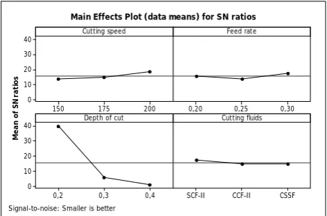
Fig. 1. S/N ratio values for tool wear.
M
e
a
n
of
S
N
r
a
ti
os
200 175 150 -42
-44
-46
-48 -50
0,30 0,25 0,20
0,4 0,3 0,2 -42
-44
-46
-48
-50
CSSF CCF-II SCF-II
Cutting speed Feed rate
Depth of cut Cutting fluids
Main Effects Plot (data means) for SN ratios
Signal-to-noise: Smaller is better
Fig. 2. S/N ratio values for Fx.
From the S/N ratio analysis in Figs. 1-3, the optimal machining conditions were 200 m/min cutting speed (level 3), 0.30 mm/rev feed rate (level 3), 0.2 mm depth of cut (level 1) and SCF-II (8% EP) cutting fluid (level 1) for tool wear, 150 m/min cutting speed (level 1), 0.20 mm/rev feed rate (level 1), 0.2 mm depth of cut (level 1) and CCF-II (8% EP) cutting fluid (level 2) for Fx and 150 m/min cutting speed (level 1), 0.20 mm/rev feed rate (level 1), 0.2
mm depth of cut (level 1) and SCF-II (8% EP) cutting fluid (level 1) for Fy, respectively.
M
e
a
n
of
S
N
r
a
ti
os
200 175 150 -42
-44 -46 -48 -50
0,30 0,25 0,20
0,4 0,3 0,2 -42 -44
-46 -48 -50
CSSF CCF-II SCF-II
Cutting speed Feed rate
Depth of cut Cutting fluids
Main Effects Plot (data means) for SN ratios
Signal-to-noise: Smaller is better
Fig. 3. S/N ratio values for Fy.
C. Analysis of Variance (ANOVA)
ANOVA was used to determine the significant parameters influencing the tool wear and force components in the milling of AISI 304. Tables 6-8 showed the summary of S/N values and ANOVA results for tool wear, Fx and Fy, respectively. In this
TABLE VI
SUMMARY OF S/N VALUES AND ANOVA RESULTS FOR TOOL WEAR
Factor
Degree of Freedom
(DF)
Average S/N Values Sum of
squares
Mean square
Percentage of contribution (%)
Level 1 Level 2 Level 3
Cutting speed 2 13.742 14.658 18.471 0.15523 0.07762 10.52
Feed rate 2 15.729 13.666 17.476 0.08654 0.04327 5.86
Depth of cut 2 40.000 5.777 1.095 1.20748 0.60374 81.82
Cutting fluids 2 17.400 14.737 14.734 0.02658 0.01329 1.80
Error 0 0 - -
Total 8 1.47583 100
TABLE VII
SUMMARY OF S/N VALUES AND ANOVA RESULTS FOR FX
Factor
Degree of Freedom
(DF)
Average S/N Values Sum of
squares
Mean square
Percentage of contribution (%)
Level 1 Level 2 Level 3
Cutting speed 2 -45.89 -47.14 -46.57 1634.9 817.4 3.20
Feed rate 2 -45.77 -47.13 -46.70 1829.6 914.8 3.59
Depth of cut 2 -42.71 -47.03 -49.85 46112.9 23056.4 90.39
Cutting fluids 2 -46.53 -46.03 -47.04 1440.2 720.1 2.82
Error 0 0 - -
[image:4.595.46.282.84.240.2] [image:4.595.316.550.190.345.2] [image:4.595.46.282.273.433.2]TABLE VIII
SUMMARY OF S/N VALUES AND ANOVA RESULTS FOR FY
Factor
Degree of Freedom
(DF)
Average S/N Values Sum of
squares
Mean square
Percentage of contribution (%)
Level 1 Level 2 Level 3
Cutting speed 2 -44.85 -46.28 -45.33 1740.7 870.3 3.76
Feed rate 2 -44.72 -46.30 -45.43 1844.7 922.3 3.98
Depth of cut 2 -41.30 -46.08 -49.08 42672.7 21336.3 92.14
Cutting fluids 2 -45.05 -45.59 -45.82 56.0 28.0 0.12
Error 0 0 - -
Total 8 46314.0 100
study, analysis was a level of significance as 5% and level of confidence as 95%.
IV. CONCLUSION
This study discussed an application of Taguchi experimental method for investigating the influence of milling parameters and cutting fluid types on the tool wear and forces during milling of AISI 304 stainless steel. In the milling experiments, different cutting speed, feed rate, depth of cut and cutting fluids were utilized. Multiple regression analysis was performed to indicate the fitness of experimental measurements. Regression models obtained from tool wear, Fx and Fy measurements matched very well with the experimental data (R2>0.80).
The level of importance of the machining parameters on the tool wear and force was determined by ANOVA. Based on this study, the following conclusions can be drawn for the milling conditions:
The optimal machining condition for tool wear was 200 m/min cutting speed (level 3), 0.30 mm/rev feed rate (level 3), 0.2 mm depth of cut (level 1) and SCF-II (8% EP) cutting fluid (level 1).
The optimal machining condition for Fx was 150 m/min cutting speed (level 1), 0.20 mm/rev feed rate (level 1), 0.2 mm depth of cut (level 1) and CCF-II (8% EP) cutting fluid (level 2).
The optimal machining condition for Fy was 150 m/min cutting speed (level 1), 0.20 mm/rev feed rate (level 1), 0.2 mm depth of cut (level 1) and SCF-II (8% EP) cutting fluid (level 1).
The depth of cut had a greater influence on the tool wear and force components.
It was found that SCF-II and CCF-II had more considerable effect on the tool wear and force components with respect to optimum machining conditions than that of CSSF.
REFERENCES
[1] W. Belluco, and L. De Chiffre, “Performance evaluation of vegetable-based oils in drilling austenitic stainless steel,” J. Mater. Process. Techno., vol. 148, pp. 171-176, 2004.
[2] E. Kuram, “Investigation of vegetable-based cutting fluids performance in drilling,” M.Sc. Thesis, Gebze Institute of Technology, Gebze, Turkey, 2009.
[3] B. Ozcelik, E. Kuram, E. Demirbas, and E. Şık, “Optimization of surface roughness in drilling using vegetable based cutting oils developed from sunflower oil,” Ind. Lubri. Tribol., 2010 (in press). [4] B. Ozcelik, E. Demirbas, E. Kuram, E. Şık, and I.N. Tansel, “The performance of vegetable oils developed from sunflower and canola oils in drilling AISI 304 materials,” in I. National Metal Cutting Symposium, Yıldız Technical University, Istanbul, 2-3 October 2009, pp. 121-129.
[5] B. Ozcelik, E. Demirbas, E. Kuram, and E. Şık, “Investigation of vegetable oils performance in drilling developed from refined sunflower oil by surface roughness,” in V. Congress on Machine Design and Production Technologies, Konya, 17-18 October 2009, pp. 39-46.
[6] W. Belluco, and L. De Chiffre, “Testing of vegetable-based cutting fluids by hole making operations,” Lubri. Eng., vol. 57, pp.12-16, 2001.
[7] L. De Chiffre, and W. Belluco, “Investigations of cutting fluid performance using different machining operations,” Lubri. Eng., vol. 58, pp. 22-29, 2002.
[8] M. A. Xavior, and M. Adithan, “Determining the influence of cutting fluids on tool wear and surface roughness during turning of AISI 304 austenitic stainless steel,” J. Mater. Process. Technol., vol. 209, pp. 900-909, 2009.
[9] W. Belluco, and L. De Chiffre, “Surface integrity and part accuracy in reaming and tapping stainless steel with new vegetable based cutting oils,” Tribo. Inter., vol. 35, pp. 865-870, 2002.
[10] L. De Chiffre, and W. Belluco, Z. Zeng, “An investigation of reaming test parameters used for cutting fluid evaluations,” Lubri. Eng., vol. 57, pp. 24-28, 2001.
[11] J. M. Vieira, A. R. Machado, and E. O. Ezugwu, “Performance of cutting fluids during face milling of steels,” J. Mater. Process. Technol., vol. 116, pp. 244-251, 2001.
[12] K. A. Abou-El-Hossein, “Cutting fluid efficiency in end milling of AISI 304 stainless steel,” Ind. Lubri. Tribo., vol. 60, pp.115-120, 2008.