Abstract—In this paper, a pneumatic worm-like micro robot with active force control (AFC) capability is modelled and simulated in a constrained environment (pipe). A mathematical model that represents the dynamic characteristics of the worm-like micro robot is first presented. Then, the dynamic response of the robot system subjected to different input excitations is investigated. A proportional-integral-derivative (PID) controller is applied to the micro robot system to follow the desired trajectory while an AFC controller is utilized to reject the unwanted disturbances which may be created due to frictional forces or fluid viscosity in the pipe. The control system is tuned so that an accurate trajectory tracking is possible. The performance of the control system under different types of disturbances is evaluated through a rigorous simulation study. The obtained results clearly demonstrate an effective trajectory tracking capability of the worm-like micro robot in spite of the negative effects of the external disturbances.
Index Terms—Active Force Control, Micro Robot, PID Controller, Robust Tracking, In-pipe.
I. INTRODUCTION
Micro robotics is a field that has generated much interest amongst researchers and robot engineers alike due to its potentials operating in adverse working conditions and constrained environments. Examples can be seen in micro robots performing various tasks such as exploration and inspection in industrial pipes that can be associated with petroleum piping installations, chemical plants, heat exchangers, and gas or water supply systems; a much smaller scale robotic system may be applicable to carry out endoscopic procedure in vessels of the human body. An in-pipe inspection micro robot is useful to inspect the state and conditions of the pipe to detect leaks, cracks or modification of cross section in pipe lines. The robot is able to move effectively in the pipe and transport exteroceptive sensors that give different results such as finding or detecting the position/location and type of problem and measurements about the environment.
Some basic research on mobile micro robotic mechanisms for use in pipes have been reported, such as those that are driven by piezoelectric actuators [1, 2, 3], by giant magnetostrictive actuators [4] by pneumatic actuators [5, 6], or by
Manuscript received April 14, 2010.
M. Mailah is with the Universiti Teknologi Malaysia (UTM), 81310 Skudai, Johor, Malaysia (phone: 607-5534562; fax: 607-5566159; e-mail: [email protected]).
Y. Sabzehmeidani is with the Universiti Teknologi Malaysia (UTM), 81310 Skudai, Johor, Malaysia (e-mail: yaser7002@ gmail.com).
M. Hussein is with the Universiti Teknologi Malaysia (UTM), 81310 Skudai, Johor, Malaysia (e-mail: [email protected]).
electromagnetic actuators [7].
However, most of these robots are still in the developmental stage and certain problems still have to be addressed and solved before they become practical. Such micro robots for small pipes have low pulling force and have difficulty negotiating curved pipes or vertical pipes. Besides, commercial charge-coupled device (CCD) cameras are too big to mount on these robots.
Lim et al. invented an inchworm like micro robot by using only one pneumatic line [8]. It is based on drilling different-sized micro holes in two plates among three chambers. The rear clamp, the elongation module, and the front clamp work sequentially as the air flows to each chamber. It enables the robot not only to generate inchworm like locomotion, but also to allow significant reduction of the stiffness of pneumatic lines and the drag force due to one pneumatic line. In order to operate the robot efficiently, the stroke according to the supplied pneumatic pressure is investigated.
In another design, a pneumatic flexible robot prototype for in-pipe inspection was designed and experimented as described in [9]. A dynamic model which takes into account the flexibility, damping and friction was developed. A number of experiments were carried out in order to characterize the robot and provide the input for the numerical model. The model was validated by comparing the experimental and numerical robot gait in time domain. The robot motion for different pipes network geometry is also presented in the research. The works described above mostly focus on the principle of actuation and assume an open loop control configuration that does not include sensory feedback information and control algorithm for critical task applications.
In the proposed research, we incorporate a robust feedback control mechanism into a pneumatically actuated micro robot taking into account the robust tracking performance in a constrained environment in pipe. The strategy used is based on active force control (AFC) technique that has been successfully applied to many dynamical systems [10-13]. Pioneering AFC work applied to robotic manipulator was presented by Hewit and Burdess (1981), in which an efficient disturbance rejection technique was established to facilitate the robust motion control of the dynamical system in the presence of disturbances, parametric uncertainties and changes that are commonly prevalent in the real-world environment [10]. Mailah et al. investigated the usefulness of the AFC method by introducing intelligent mechanisms to approximate the mass or inertia matrix of the dynamic system to trigger the compensation effect of the controller. It was
Modelling and Control of a Worm-Like Micro
Robot with Active Force Control Capability
recognized that the AFC was rob theory as well as in
AFC method is extended to correct the accuracy, stroke and reach point of
tracking performance
and later simulated with the active force control mode incorporated.
II. A
specifically produces
five phases illustrated by schematic drawings in
(a)
[image:2.612.71.296.220.386.2](c)
Figure
part: The rear bladder expands and pushes onto the inner pipe wall, holding the robot fixed (b) Second part: The robot body stretches (c) Third part: The front bladder expands (d) Fourth part: The rear bladder
deflates executing the net gait
B
chambers
with control volumes (CV pneumatic resistance is
Where, the mass
terms of the pneumatic capacitances expressed as:
Where,
and
By
recognized that the AFC was rob theory as well as in
AFC method is extended to correct the accuracy, stroke and reach point of the
tracking performance
and later simulated with the active force control mode incorporated.
. MODELING AND
A. Mechanism of Robot Movement
The proposed study considers that the specifically intended
produces a worm
five phases illustrated by schematic drawings in
(a)
(c)
(e)
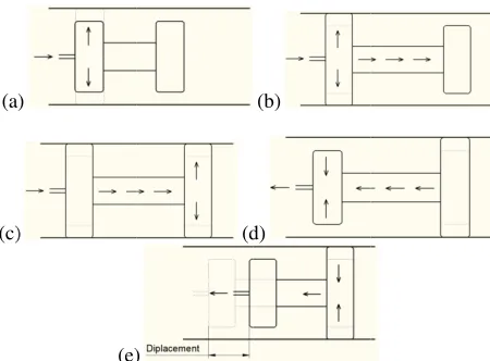
Figure 1: Mechanism of micro robot movement, (a) First part: The rear bladder expands and pushes onto the inner pipe wall, holding the robot fixed (b) Second part: The robot body stretches (c) Third part: The front bladder expands (d) Fourth part: The rear bladder
deflates executing the net gait
B. Mathematical Formulation For the given dynamic system chambers and bladders
with control volumes (CV pneumatic resistance is
Where, is defined in terms of the mass rate of flow the input pressure,
mass flow rate of
terms of the pneumatic capacitances expressed as:
Where,
and
By inserting Eq. (1) into Eq. (2), we have recognized that the AFC was rob theory as well as in practice [1
AFC method is extended to correct the accuracy, stroke and the micro robot
tracking performance. The m
and later simulated with the active force control mode
ODELING AND SIMULATION OF
Mechanism of Robot Movement
The proposed study considers that the intended for in-pipe
worm-like locomotion. The gait cycle consists of five phases illustrated by schematic drawings in
(d)
(e)
Mechanism of micro robot movement, (a) First part: The rear bladder expands and pushes onto the inner pipe wall, holding the robot fixed (b) Second part: The robot body stretches (c) Third part: The front bladder expands (d) Fourth part: The rear bladder deflates (e) Fifth part: The robot body deflates executing the net gait
Mathematical Formulation For the given dynamic system
and bladders in a cylindrical space with control volumes (CV1 and CV
pneumatic resistance is given as
is defined in terms of the mass rate of flow input pressure, is the output pressure, and
rate of the fluid. The differential mass flow rate in terms of the pneumatic capacitances
inserting Eq. (1) into Eq. (2), we have
recognized that the AFC was robust and effective both in [12, 13]. In this research, the AFC method is extended to correct the accuracy, stroke and micro robot, all pertaining to robust
micro robot shall be
and later simulated with the active force control mode
IMULATION OF MICRO R
Mechanism of Robot Movement
The proposed study considers that the pipe application
like locomotion. The gait cycle consists of five phases illustrated by schematic drawings in
(b)
(d)
Mechanism of micro robot movement, (a) First part: The rear bladder expands and pushes onto the inner pipe wall, holding the robot fixed (b) Second part: The robot body stretches (c) Third part: The front bladder expands (d) Fourth deflates (e) Fifth part: The robot body
Mathematical Formulation
For the given dynamic system comprising in a cylindrical space
and CV2) as shown in Fig. 2,
given as:
is defined in terms of the mass rate of flow
output pressure, and
The differential mass flow rate in terms of the pneumatic capacitances (C1 and
inserting Eq. (1) into Eq. (2), we have:
ust and effective both in In this research, the AFC method is extended to correct the accuracy, stroke and , all pertaining to robust icro robot shall be modelled and later simulated with the active force control mode
ROBOT SYSTEM
The proposed study considers that the robot is application and that it like locomotion. The gait cycle consists of five phases illustrated by schematic drawings in Fig. 1 [8].
Mechanism of micro robot movement, (a) First part: The rear bladder expands and pushes onto the inner pipe wall, holding the robot fixed (b) Second part: The robot body stretches (c) Third part: The front bladder expands (d) Fourth deflates (e) Fifth part: The robot body
comprising a series of air in a cylindrical space (inside pipe)
own in Fig. 2, the (1) is defined in terms of the mass rate of flow, i
output pressure, and is the The differential mass flow rate in
and C2) can be
(2)
(3) ust and effective both in
In this research, the AFC method is extended to correct the accuracy, stroke and , all pertaining to robust modelled and later simulated with the active force control mode
YSTEM
robot is it like locomotion. The gait cycle consists of
Mechanism of micro robot movement, (a) First part: The rear bladder expands and pushes onto the inner pipe wall, holding the robot fixed (b) Second part: The robot body stretches (c) Third part: The front bladder expands (d) Fourth deflates (e) Fifth part: The robot body
air (inside pipe) the (1) is the The differential mass flow rate in can be (2)
(3)
Using Eq. (1)
Figure
Eq. (3) can also be expressed
Similar to CV CV2 and CV
Figure By using
From Eq. (
!
For the displacement of
"#" $"
Substituting
% ! &
'
For the above condition, since and rear bladder
displacement is friction) and not change,
Eq. (1), the following expression can
Figure 2: Free body diagram can also be expressed
Similar to CV1 and referring to Fig. 3, the expressions for
and CV3 are given as follows: &
( (
Figure 3: Free body diagram By using Eq. (5), can be written
%
Eq. (8), can be determined
! ( (
displacement of
")" * '**
Substituting Eqs. (8) and (
%
! ( ( '
+
e above condition, since
and rear bladders is assumed to sufficiently displacement is relatively
and that the lengths of the change, Eq. (12) could be simplif
, the following expression can
ree body diagram related to can also be expressed as:
and referring to Fig. 3, the expressions for are given as follows:
&
ree body diagram related to can be written as:
,
can be determined as: displacement of section, it is given as
* - . / 0
) and (9) into Eq. (6)
'
' 1
e above condition, since the movement of
assumed to sufficiently relatively small enough
that the lengths of the front and rear bladder could be simplified
, the following expression can be written as:
related to CV1 and CV
and referring to Fig. 3, the expressions for
related to CV2 and CV
as:
!1 as:
it is given as:
0
Eq. (6), we have:
!1
! !
the movement of the assumed to sufficiently quick while
small enough (neglecting the front and rear bladder
ied as:
(4) be written as:
(5)
and CV2
(6) and referring to Fig. 3, the expressions for
(7)
(8)
and CV3
1 (9)
(10)
(11)
1 ! &
+
Using Laplace transformation, the displacemen
2
For testing
tracking the desired locomotion accurately, input sources
functions determine
namely the PID and AFC controllers shall be applied and incorporated into the mi
A
most commonly used control algorithm in industry and has been universally accepted in industrial control
popularity of PID controllers can be attributed partly robust performance in a wide range of operating conditions and partly to their functional simplicity, which allows engineers to operate them in a simple, straightforward manner
controller
The basic idea behind a PID controller is to read a sensor, then compute the desired actuator output by calculating proportional, integral, and derivative responses and summing those three components to com
controller calculation (algorithm) involves three separate parameters;
The
3 45
where
derivative gains, respectively. In this study, the Ziegler
parameters. The final gains
$4
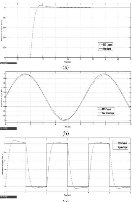
the gains can be seen in Fig. 5 throughout the simulation study.
6
Using Laplace transformation, the displacement can be found as:
27 87 9:;
For testing the
tracking the desired locomotion accurately, input sources in the form of
functions via feedback control techniques determine the system responses.
namely the PID and AFC controllers shall be applied and incorporated into the mi
A. PID control Proportional
most commonly used control algorithm in industry and has been universally accepted in industrial control
popularity of PID controllers can be attributed partly robust performance in a wide range of operating conditions and partly to their functional simplicity, which allows engineers to operate them in a simple, straightforward manner. A schematic diagram of system
[image:3.612.316.540.45.388.2] [image:3.612.78.293.403.472.2]controller is shown in
Figure
The basic idea behind a PID controller is to read a sensor, then compute the desired actuator output by calculating proportional, integral, and derivative responses and summing those three components to com
controller calculation (algorithm) involves three separate parameters; the proportional,
The PID control algorithm is
45 $ =<
here $ , $4, and
derivative gains, respectively. In this study, the Ziegler–Nichols
parameters. The final gains
>.?, $5
the gains can be seen in Fig. 5 throughout the simulation study.
!@ ! !
Using Laplace transformation, the
t can be found as:
ABC CC BCD
EFGH IJKGLHM ;
III. CONTROL
the system effectiveness in producing and tracking the desired locomotion accurately,
in the form of step
via feedback control techniques system responses.
namely the PID and AFC controllers shall be applied and incorporated into the micro robot
PID control
Proportional-Integral-Derivative (PID) control is the most commonly used control algorithm in industry and has been universally accepted in industrial control
popularity of PID controllers can be attributed partly robust performance in a wide range of operating conditions and partly to their functional simplicity, which allows engineers to operate them in a simple, straightforward
chematic diagram of system is shown in Fig. 4.
Figure 4: Schematic diagram of system
The basic idea behind a PID controller is to read a sensor, then compute the desired actuator output by calculating proportional, integral, and derivative responses and summing those three components to com
controller calculation (algorithm) involves three separate proportional, i
control algorithm is given as follows:
$5N
and $5 are the proportional, integral and derivative gains, respectively. In this study, the method is employed to tune the PID parameters. The final gains were determined as
>0. The resultant tracking control based on the gains can be seen in Fig. 5
throughout the simulation study.
! ,
Using Laplace transformation, the transfer function based on
D
H
M AC BCC C DO
ONTROL SCHEMES
effectiveness in producing and tracking the desired locomotion accurately, we applied
step, square and sin via feedback control techniques
system responses. Two types of controllers, namely the PID and AFC controllers shall be applied and
cro robot system.
Derivative (PID) control is the most commonly used control algorithm in industry and has been universally accepted in industrial control
popularity of PID controllers can be attributed partly robust performance in a wide range of operating conditions and partly to their functional simplicity, which allows engineers to operate them in a simple, straightforward chematic diagram of system employing a PID
Schematic diagram of system
The basic idea behind a PID controller is to read a sensor, then compute the desired actuator output by calculating proportional, integral, and derivative responses and summing those three components to compute the output. The PID controller calculation (algorithm) involves three separate
integral and derivative given as follows:
are the proportional, integral and derivative gains, respectively. In this study, the method is employed to tune the PID
were determined as
The resultant tracking control based on and these gains shall be used throughout the simulation study.
'
(13) transfer function based on
DO (14)
effectiveness in producing and we applied three
sinusoidal input via feedback control techniques in order to
Two types of controllers, namely the PID and AFC controllers shall be applied and
Derivative (PID) control is the most commonly used control algorithm in industry and has been universally accepted in industrial control [14]. The popularity of PID controllers can be attributed partly to their robust performance in a wide range of operating conditions and partly to their functional simplicity, which allows engineers to operate them in a simple, straightforward employing a PID
Schematic diagram of system
The basic idea behind a PID controller is to read a sensor, then compute the desired actuator output by calculating proportional, integral, and derivative responses and summing pute the output. The PID controller calculation (algorithm) involves three separate derivative terms given as follows:
(15) are the proportional, integral and derivative gains, respectively. In this study, the method is employed to tune the PID were determined as $ P? The resultant tracking control based on
hese gains shall be used (13) transfer function based on
(14)
effectiveness in producing and three input in order to Two types of controllers, namely the PID and AFC controllers shall be applied and
Derivative (PID) control is the most commonly used control algorithm in industry and has . The to their robust performance in a wide range of operating conditions and partly to their functional simplicity, which allows engineers to operate them in a simple, straightforward employing a PID
The basic idea behind a PID controller is to read a sensor, then compute the desired actuator output by calculating proportional, integral, and derivative responses and summing pute the output. The PID controller calculation (algorithm) involves three separate terms. (15) are the proportional, integral and derivative gains, respectively. In this study, the method is employed to tune the PID
P?, The resultant tracking control based on hese gains shall be used
Figure 5:
B. Active Force Control
The research on active force control (AFC) is initiated by Johnson (1971) and later Davison (1976) based on the principle of invariance and the classic
of motion
to design a feedback controller that will ensure the system setpoint remains unchanged even in the presence of the disturbances or adverse operating and loading conditions provided that the actual disturbances can be modelled effectively. Hewit and Burdess (1981) proposed a more complete package of the system such that the nature of disturbances is oblivious to the system and that it is readily applied to multi
Thus, an effective
robust motion control of dynamical systems in the presence of disturbances
commonly
et al. extended the usefulness of the method by intro intelligent mechanisms to approximate the mass or inertia matrix of the dynamic system to trigger the compensation effect of the controller
technique that relies on the appropriate estimation of the inertial or mass
measurements of the acceleration and force signals induced by the system
For theoretical simulation, it is normal that perfect modelling of the sensors is assumed and
totally neglected.
subjected to a number of disturbances remains stable and Performance of
wave and (c Active Force Control
The research on active force control (AFC) is initiated by Johnson (1971) and later Davison (1976) based on the principle of invariance and the classic
of motion [15, 16]. It has been demonstrated
to design a feedback controller that will ensure the system setpoint remains unchanged even in the presence of the disturbances or adverse operating and loading conditions provided that the actual disturbances can be modelled y. Hewit and Burdess (1981) proposed a more complete package of the system such that the nature of disturbances is oblivious to the system and that it is readily applied to multi-degree of freedom dynamic systems Thus, an effective method
robust motion control of dynamical systems in the presence of disturbances, parametric
commonly prevalent in the real
extended the usefulness of the method by intro intelligent mechanisms to approximate the mass or inertia matrix of the dynamic system to trigger the compensation effect of the controller
technique that relies on the appropriate estimation of the inertial or mass parameters of the dynamic system and the measurements of the acceleration and force signals induced by the system if practical implementation is ever considered. For theoretical simulation, it is normal that perfect modelling of the sensors is assumed and
totally neglected. In AFC, it is shown that the system subjected to a number of disturbances remains stable and
(a)
(b)
(c) Performance of PID controller
c) square input Active Force Control
The research on active force control (AFC) is initiated by Johnson (1971) and later Davison (1976) based on the principle of invariance and the classic
. It has been demonstrated
to design a feedback controller that will ensure the system setpoint remains unchanged even in the presence of the disturbances or adverse operating and loading conditions provided that the actual disturbances can be modelled y. Hewit and Burdess (1981) proposed a more complete package of the system such that the nature of disturbances is oblivious to the system and that it is readily
degree of freedom dynamic systems method has been es
robust motion control of dynamical systems in the presence , parametric uncertainties
in the real-world environment. extended the usefulness of the method by intro intelligent mechanisms to approximate the mass or inertia matrix of the dynamic system to trigger the compensation
[11, 12, 17]. The AFC method technique that relies on the appropriate estimation of the
parameters of the dynamic system and the measurements of the acceleration and force signals induced if practical implementation is ever considered. For theoretical simulation, it is normal that perfect modelling of the sensors is assumed and that noises in the sensors are In AFC, it is shown that the system subjected to a number of disturbances remains stable and
PID controller for (a) step, input functions
The research on active force control (AFC) is initiated by Johnson (1971) and later Davison (1976) based on the principle of invariance and the classic Newton’s second law . It has been demonstrated that it is possible to design a feedback controller that will ensure the system setpoint remains unchanged even in the presence of the disturbances or adverse operating and loading conditions provided that the actual disturbances can be modelled y. Hewit and Burdess (1981) proposed a more complete package of the system such that the nature of disturbances is oblivious to the system and that it is readily
degree of freedom dynamic systems has been established to facilitate robust motion control of dynamical systems in the presence
uncertainties and changes world environment. extended the usefulness of the method by intro intelligent mechanisms to approximate the mass or inertia matrix of the dynamic system to trigger the compensation
The AFC method technique that relies on the appropriate estimation of the
parameters of the dynamic system and the measurements of the acceleration and force signals induced if practical implementation is ever considered. For theoretical simulation, it is normal that perfect modelling that noises in the sensors are In AFC, it is shown that the system subjected to a number of disturbances remains stable and for (a) step, (b) sine
robust via the compensating action of the control strategy. A more detailed description on the mathematical trea related to the derivation of important equations and stability criterion, can be found in
concept of AFC applied to presented with reference to Fig.
The notations used in
The
following expression:
F can be readily measured by means of a using an accelerometer.
perfect model [11]
give the ultimate AFC signal command to be embedded with an outer control loop. This creates a two degree
controller that could provide excellent overall system performance provided that the measurement and estimated parameters were appropriately acquired. The outer control loop can be a proportional
controller, resolved mo
intelligent controller or others deemed suitable. It is apparent that a
cause the output to disturbances
G
A
open loop system, by first generating the world coordinate error vector, which would then be processed through a controller function,
that maybe represented by Eq (15).
burden in AFC is the multiplication of the estimated inertia parameter
component Mailah
demonstrated the effectiveness of the AFC scheme applied to rigid robot arms.
robust intelligent AFC method that is capable of controlling a vehicle suspension system
introduced
Desired Position
robust via the compensating action of the control strategy. A more detailed description on the mathematical trea related to the derivation of important equations and stability criterion, can be found in
[image:4.612.72.299.112.210.2]concept of AFC applied to presented with reference to Fig.
Figure 6: A schematic diagram The notations used in
G(s) : Ga(s) :
Gc(s) :
KAFC :
H(s) : F : F* : m : a :
he estimated disturbance following expression:
F* =
can be readily measured by means of a using an accelerometer.
perfect model, crude approximation [11]. F* is then passed through a
give the ultimate AFC signal command to be embedded with an outer control loop. This creates a two degree
controller that could provide excellent overall system performance provided that the measurement and estimated parameters were appropriately acquired. The outer control loop can be a proportional
controller, resolved mo
intelligent controller or others deemed suitable. It is apparent that a suitable choice of
cause the output to disturbances such that:
Ga(s)H(s) = 1
A set of outer
open loop system, by first generating the world coordinate error vector, which would then be processed through a controller function,
that maybe represented by Eq (15).
burden in AFC is the multiplication of the estimated inertia parameter with the angular acceleration of the
component before being fed into the AFC feedforward loop. Mailah et al. [18]
demonstrated the effectiveness of the AFC scheme applied to rigid robot arms.
robust intelligent AFC method that is capable of controlling a vehicle suspension system
introduced disturbances. Gc(s) Desired Position Controller +
-robust via the compensating action of the control strategy. A more detailed description on the mathematical trea related to the derivation of important equations and stability criterion, can be found in [10]
concept of AFC applied to a dynamic rotational system is presented with reference to Fig.
A schematic diagram The notations used in Fig. 6 are as follows:
Dynamic system transfer function Actuator transfer function
Outer loop controller AFC constant Weighting function Applied force Estimated force Estimated mass Linear acceleration estimated disturbance is following expression:
= F – m a
can be readily measured by means of a
using an accelerometer. m may be obtained by assuming a crude approximation
passed through a
give the ultimate AFC signal command to be embedded with an outer control loop. This creates a two degree
controller that could provide excellent overall system performance provided that the measurement and estimated parameters were appropriately acquired. The outer control loop can be a proportional
controller, resolved motion acceleration controller (RMAC), intelligent controller or others deemed suitable. It is apparent
suitable choice of H(s) needs to be obtained that cause the output to be made invariant with respect to the
such that: outer control loop control
open loop system, by first generating the world coordinate error vector, which would then be processed through a controller function, Gc(s), typically a classic P
that maybe represented by Eq (15).
burden in AFC is the multiplication of the estimated inertia with the angular acceleration of the
before being fed into the AFC feedforward loop. ], Mailah [11] and Pitowarno
demonstrated the effectiveness of the AFC scheme applied to rigid robot arms. Gigih et al.
robust intelligent AFC method that is capable of controlling a vehicle suspension system and
disturbances. Ga(s) KAFC F Actuator H(s) + +
robust via the compensating action of the control strategy. A more detailed description on the mathematical trea related to the derivation of important equations and stability
[10]. For brevity, the underlying a dynamic rotational system is presented with reference to Fig. 6.
A schematic diagram of an AFC scheme are as follows:
ynamic system transfer function Actuator transfer function Outer loop controller AFC constant Weighting function force force mass acceleration
is obtained by considering the
can be readily measured by means of a force
may be obtained by assuming a crude approximation or intelligent methods
passed through a weighting function give the ultimate AFC signal command to be embedded with an outer control loop. This creates a two degree
controller that could provide excellent overall system performance provided that the measurement and estimated parameters were appropriately acquired. The outer control loop can be a proportional-integral-derivative (PID) tion acceleration controller (RMAC), intelligent controller or others deemed suitable. It is apparent
needs to be obtained that be made invariant with respect to the
control is applied to the above open loop system, by first generating the world coordinate error vector, which would then be processed through a
typically a classic P
that maybe represented by Eq (15). The main computational burden in AFC is the multiplication of the estimated inertia
with the angular acceleration of the
before being fed into the AFC feedforward loop. and Pitowarno
demonstrated the effectiveness of the AFC scheme applied to . [20] have equally shown a robust intelligent AFC method that is capable of controlling a and effectively suppressing the
G(s) Disturbances m F + + + -Force Sensor Accelero meter Dynamic System Estimated Mass F*
robust via the compensating action of the control strategy. A more detailed description on the mathematical treatment related to the derivation of important equations and stability . For brevity, the underlying a dynamic rotational system is
of an AFC scheme
ynamic system transfer function
obtained by considering the
(16 force sensor and a may be obtained by assuming a
or intelligent methods function H(s) to give the ultimate AFC signal command to be embedded with an outer control loop. This creates a two degree-of-freedom controller that could provide excellent overall system performance provided that the measurement and estimated parameters were appropriately acquired. The outer control derivative (PID) tion acceleration controller (RMAC), intelligent controller or others deemed suitable. It is apparent needs to be obtained that can be made invariant with respect to the (2) is applied to the above open loop system, by first generating the world coordinate error vector, which would then be processed through a typically a classic PID controller
The main computational burden in AFC is the multiplication of the estimated inertia
with the angular acceleration of the dynamic before being fed into the AFC feedforward loop. and Pitowarno et al. [19] have demonstrated the effectiveness of the AFC scheme applied to have equally shown a robust intelligent AFC method that is capable of controlling a ffectively suppressing the
1/s2 Actual Position
AFC
a
robust via the compensating action of the control strategy. A tment related to the derivation of important equations and stability . For brevity, the underlying a dynamic rotational system is
obtained by considering the
6) a may be obtained by assuming a or intelligent methods to give the ultimate AFC signal command to be embedded with freedom controller that could provide excellent overall system performance provided that the measurement and estimated parameters were appropriately acquired. The outer control derivative (PID) tion acceleration controller (RMAC), intelligent controller or others deemed suitable. It is apparent can be made invariant with respect to the (2) is applied to the above open loop system, by first generating the world coordinate error vector, which would then be processed through a ller The main computational burden in AFC is the multiplication of the estimated inertial dynamic before being fed into the AFC feedforward loop. have demonstrated the effectiveness of the AFC scheme applied to have equally shown a robust intelligent AFC method that is capable of controlling a ffectively suppressing the
A useful point to note is that, the constant can effectively serve as a
scheme (AFC by simply setting the between value of effect of percentage this study.
IV For th MATLAB robot are Parameter ! $! #!
The applied disturbance considered in the study is a harmonic force that emulates a constant vibratory excitation with a magnitude of 40 N and frequency, 10
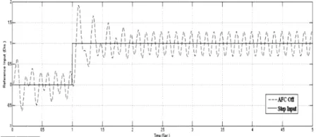
the following function, 40 sin 10
[image:4.612.322.534.207.343.2]disturbance shall act as a test for the robustness of the system performance via observation of the response obtained.
Figure 7:
For simulating th
PID plus AFC, a number of input that are related to
functions. The responses to these inputs are shown in Figs. and 9.
Actual Position
A useful point to note is that, the constant effectively serve as a
scheme (AFC – OFF) or PID plus AFC method (AFC by simply setting the K
between value of KAFC can also be experimented to show the
effect of percentage KAFC
this study.
IV. SIMULATION
For the proposed simulation study of the MATLAB and Simulink was used
[image:4.612.326.534.438.553.2]are shown in Table
Table I: Parameters of micro robot arameter Value
?7P ?70Q
! ?7.
! ?7> RS
! ?7?0T >?
The applied disturbance considered in the study is a harmonic force that emulates a constant vibratory excitation with a magnitude of 40 N and frequency, 10
the following function, 40 sin 10
disturbance shall act as a test for the robustness of the system performance via observation of the response obtained.
The applied harmonic
For simulating the proposed control schemes, i.e., PID and PID plus AFC, a number of input
related to step, sinusoidal and
functions. The responses to these inputs are shown in Figs. A useful point to note is that, the constant
effectively serve as a mode switch between the PID only OFF) or PID plus AFC method (AFC
KAFC to 0 or 1 respectively.
can also be experimented to show the
AFC which however is not covered in
IMULATION RESULTS AND
e proposed simulation study of the Simulink was used. The
shown in Table I.
arameters of micro robot alue Parameter
P 0Q U . 2 ++ S V + m
The applied disturbance considered in the study is a harmonic force that emulates a constant vibratory excitation with a magnitude of 40 N and frequency, 10 rad/s
the following function, 40 sin 10t as shown in Fig. disturbance shall act as a test for the robustness of the system performance via observation of the response obtained.
harmonic disturbance considered in the study
e proposed control schemes, i.e., PID and PID plus AFC, a number of input sources
, sinusoidal and
functions. The responses to these inputs are shown in Figs.
(a)
A useful point to note is that, the constant KAFC in Fig. 6
switch between the PID only OFF) or PID plus AFC method (AFC
to 0 or 1 respectively. can also be experimented to show the
which however is not covered in
ESULTS AND DISCUSSION
e proposed simulation study of the
The parameters of micro
arameters of micro robot arameter Value
>??? +WX ?7?YZQ
>? + /??[ \ ] ^_ +[\ ?7>Q WX
The applied disturbance considered in the study is a harmonic force that emulates a constant vibratory excitation with a rad/s, i.e., according to as shown in Fig. disturbance shall act as a test for the robustness of the system performance via observation of the response obtained.
disturbance considered in the
e proposed control schemes, i.e., PID and sources were considered , sinusoidal and square wave functions. The responses to these inputs are shown in Figs.
in Fig. 6 switch between the PID only OFF) or PID plus AFC method (AFC – ON) to 0 or 1 respectively. The in can also be experimented to show the which however is not covered in
ISCUSSION
e proposed simulation study of the system, parameters of micro
alue WX +! ?YZQ T + \ +! [\ WX
The applied disturbance considered in the study is a harmonic force that emulates a constant vibratory excitation with a , i.e., according to as shown in Fig. 7. The disturbance shall act as a test for the robustness of the system performance via observation of the response obtained.
disturbance considered in the
[image:4.612.329.553.635.732.2]Figure
Figure plus
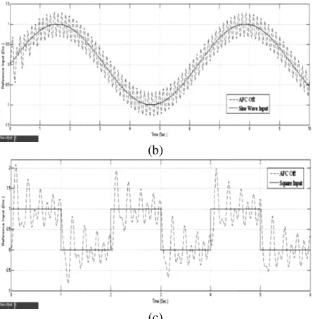
From perform the responses to Figure 8: Effect of
for PID controller only (AFC
Figure 9: Effect of harmonic force on the p plus AFC scheme
From Fig. 8, it can be seen that the perform the trajectory tracking task the responses to converge to the reference
(b)
(c)
Effect of harmonic disturbance on system response for PID controller only (AFC
conditions
(a)
(b)
(c)
Effect of harmonic force on the p AFC scheme (AFC – ON)
it can be seen that the the trajectory tracking task
converge to the reference (b)
(c)
disturbance on system response for PID controller only (AFC – OFF) for various input
conditions
(a)
(b)
(c)
Effect of harmonic force on the performance of ON) for various input conditions it can be seen that the PID controller is able to the trajectory tracking task satisfactorily by bringing
converge to the reference positions
disturbance on system response OFF) for various input
erformance of PID for various input conditions
PID controller is able to satisfactorily by bringing positions but at the disturbance on system response
PID for various input conditions PID controller is able to satisfactorily by bringing at the
expense of relatively large track ripples or oscillation
disturbance (vibratory) shown through the
clearly demonstrated that the PID
ON) manages to accurately and readily track the desired responses. This shows that the latter system is much more robust than its counterpart
disturbance at relatively high frequency pneumatically actuated micro
effectively
with the given loading and operating
In this study a pneumatic worm modelled
the PID incorporated with the AFC was employed to ensure an accurate
under the presence of operating environment tuned using the typical achieve satisfactory performance the proposed schemes
of the closed
with AFC method (AFC
the rigorous study on sensitivity analysis related to the effects of other loading and operating conditions. The possibility of performing practical
system should
The authors would like to thank the Universiti Teknologi Malaysia (UTM) for their continuous support in the research work.
[1] S. Aoshima et al.,
mobility in a thin tube.
270-278. [2] T. Idogaki et al.,
for an in
Micro Machine and Human Sciences. pp. [3] T. Matsumoto
mobile machine with piezoelectric driving force actuator.
IEEE 5th Int. Symp. Micro Machine and Human Sciences. pp. 47 [4] T. Fukuda
magnetostrictive alloy (GMA) applications to micro mobile robot as a micro actuator without power supply cables.
Workshop Micro Electro Mechanical Systems (MEMS). pp. 210 [5] Suzumori, K. and Abe T.,
pipeline inspection robots.
Int. Symp. Robotics and Manufacturing Systems. pp. 515 [6] M. Takahashi,
in-pipe microrobot applying the motion of an earthworm.
5th Int. Symp. Micro Machine and Human Sciences. pp. 35 [7] S. Iwashita
in-pipe operation micro robots.
Machine and Human Sciences. pp. 41 [8] Lim, J.,
line based inchworm
2008, Mechatronics, pp. 315
[9] A. Manuello Bertetto and M. Ruggiu,
flexible robot.
Conference on Advanced Intelligent Mechatronics. pp. 1226 [10] J.R. Hewit, J.S. Burdess, Fast
Robotics using Active Force Control
Theory, 16(5), 1981, pp. 535 expense of relatively large track
ripples or oscillation, largely due to the nature of the applied disturbance (vibratory).
shown through the second set of graphs clearly demonstrated that the PID
manages to accurately and readily track the desired responses. This shows that the latter system is much more robust than its counterpart
disturbance at relatively high frequency ically actuated micro
effectively based on the
with the given loading and operating V.
In this study a pneumatic worm
and simulated. A hybrid control strategy including the PID incorporated with the AFC was employed to ensure an accurate and robust trajectory trac
under the presence of
operating environment. The PID using the typical
achieve satisfactory performance
the proposed schemes clearly demonstrated the effectiveness closed-loop control algorithm
with AFC method (AFC
the rigorous study on sensitivity analysis related to the effects of other loading and operating conditions. The possibility of performing practical experimenta
system should also be explored and investigated.
VI. A
The authors would like to thank the Universiti Teknologi Malaysia (UTM) for their continuous support in the research work.
S. Aoshima et al., A miniature mobile robot using piezo vibration mobility in a thin tube.
278.
T. Idogaki et al.,Characteristics of piezoelectric locomotive mechanism for an in-pipe micro inspection machine.,
Micro Machine and Human Sciences. pp. Matsumoto, H. Okamoto, and M. Asano
mobile machine with piezoelectric driving force actuator.
IEEE 5th Int. Symp. Micro Machine and Human Sciences. pp. 47 T. Fukuda, H. Hosokai, H. Ohyama, H. Hashimoto,
magnetostrictive alloy (GMA) applications to micro mobile robot as a micro actuator without power supply cables.
Workshop Micro Electro Mechanical Systems (MEMS). pp. 210 Suzumori, K. and Abe T.,
pipeline inspection robots.
Int. Symp. Robotics and Manufacturing Systems. pp. 515 Takahashi, I. Hayashi,
pipe microrobot applying the motion of an earthworm.
5th Int. Symp. Micro Machine and Human Sciences. pp. 35 Iwashita, I. Hayashi, N.
pipe operation micro robots.
Machine and Human Sciences. pp. 41 Lim, J., Park, H., An, J.,
line based inchworm-like micro robot for half
2008, Mechatronics, pp. 315
A. Manuello Bertetto and M. Ruggiu,
flexible robot. Como, Italy
Conference on Advanced Intelligent Mechatronics. pp. 1226 J.R. Hewit, J.S. Burdess, Fast
botics using Active Force Control
Theory, 16(5), 1981, pp. 535
expense of relatively large tracking errors
, largely due to the nature of the applied . This is in stark contrast
second set of graphs
clearly demonstrated that the PID with AFC scheme manages to accurately and readily track the desired responses. This shows that the latter system is much more robust than its counterpart in compensating the harmonic disturbance at relatively high frequency
ically actuated micro robot is able to operate based on the closed-loop control
with the given loading and operating conditions. . CONCLUSION
In this study a pneumatic
worm-and simulated. A hybrid control strategy including the PID incorporated with the AFC was employed to ensure trajectory tracking of the robot system under the presence of the prescribed
. The PID controller was using the typical Ziegler-Nichols
achieve satisfactory performance. The simulation results clearly demonstrated the effectiveness ontrol algorithms, particularly th with AFC method (AFC – ON). Future works
the rigorous study on sensitivity analysis related to the effects of other loading and operating conditions. The possibility of experimentation on the micro robot also be explored and investigated.
ACKNOWLEDGEMENT
The authors would like to thank the Universiti Teknologi Malaysia (UTM) for their continuous support in the research work.
REFERENCES
A miniature mobile robot using piezo vibration mobility in a thin tube. 1993, ASME J. Dynam. Syst, Vol. 115, pp.
Characteristics of piezoelectric locomotive mechanism pipe micro inspection machine.,
Micro Machine and Human Sciences. pp. , H. Okamoto, and M. Asano
mobile machine with piezoelectric driving force actuator.
IEEE 5th Int. Symp. Micro Machine and Human Sciences. pp. 47 , H. Hosokai, H. Ohyama, H. Hashimoto,
magnetostrictive alloy (GMA) applications to micro mobile robot as a micro actuator without power supply cables.
Workshop Micro Electro Mechanical Systems (MEMS). pp. 210 Suzumori, K. and Abe T., Applying a flexibl
pipeline inspection robots. The Netherlands
Int. Symp. Robotics and Manufacturing Systems. pp. 515 Hayashi, and N. Iwatsuki
pipe microrobot applying the motion of an earthworm.
5th Int. Symp. Micro Machine and Human Sciences. pp. 35 , N. Iwatsuki, and K.
pipe operation micro robots. 1994. IEEE 5th Int. Symp. Micro Machine and Human Sciences. pp. 41–45.
, J., Hong, Y-S., Kim, B.,
like micro robot for half
2008, Mechatronics, pp. 315–322. A. Manuello Bertetto and M. Ruggiu, In
Como, Italy : s.n., 2001. IEEVASME International Conference on Advanced Intelligent Mechatronics. pp. 1226 J.R. Hewit, J.S. Burdess, Fast Dynamic Decoupled Control for
botics using Active Force Control, Trans. Theory, 16(5), 1981, pp. 535-542.
ing errors with substantial , largely due to the nature of the applied This is in stark contrast to the results second set of graphs (Fig. 9) in which it is
with AFC scheme manages to accurately and readily track the desired responses. This shows that the latter system is much more in compensating the harmonic disturbance at relatively high frequency. The proposed robot is able to operate loop control configuration
conditions. ONCLUSION
-like micro robot was and simulated. A hybrid control strategy including the PID incorporated with the AFC was employed to ensure ing of the robot system the prescribed disturbances
controller was
Nichols method so as to . The simulation results clearly demonstrated the effectiveness
s, particularly th . Future works may include the rigorous study on sensitivity analysis related to the effects of other loading and operating conditions. The possibility of tion on the micro robot also be explored and investigated.
CKNOWLEDGEMENT
The authors would like to thank the Universiti Teknologi Malaysia (UTM) for their continuous support in the research work.
A miniature mobile robot using piezo vibration
1993, ASME J. Dynam. Syst, Vol. 115, pp.
Characteristics of piezoelectric locomotive mechanism pipe micro inspection machine., 1995. IEEE 6th Int. Symp.
193–198.
, H. Okamoto, and M. Asano, A prototype model of micro mobile machine with piezoelectric driving force actuator.
IEEE 5th Int. Symp. Micro Machine and Human Sciences. pp. 47 , H. Hosokai, H. Ohyama, H. Hashimoto, and F. Arai
magnetostrictive alloy (GMA) applications to micro mobile robot as a micro actuator without power supply cables., 1991. IEEE Int. Workshop Micro Electro Mechanical Systems (MEMS). pp. 210
Applying a flexible microactuators to
The Netherlands : s.n., 1993. IMACS/SICE Int. Symp. Robotics and Manufacturing Systems. pp. 515–520.
Iwatsuki, The development of an pipe microrobot applying the motion of an earthworm. 1994. IEEE 5th Int. Symp. Micro Machine and Human Sciences. pp. 35–
and K. Nakahara, Development of
. IEEE 5th Int. Symp. Micro 45.
, B., Yi, B-J, One pneumatic like micro robot for half-inch pipe inspection.
In-pipe inch-worm pneumatic
: s.n., 2001. IEEVASME International Conference on Advanced Intelligent Mechatronics. pp. 1226
Dynamic Decoupled Control for
, Trans. Mechanism and Machine with substantial , largely due to the nature of the applied the results in which it is with AFC scheme (AFC – manages to accurately and readily track the desired responses. This shows that the latter system is much more in compensating the harmonic The proposed robot is able to operate configuration
like micro robot was and simulated. A hybrid control strategy including the PID incorporated with the AFC was employed to ensure ing of the robot system disturbances and controller was initially method so as to . The simulation results of clearly demonstrated the effectiveness s, particularly the PID may include the rigorous study on sensitivity analysis related to the effects of other loading and operating conditions. The possibility of tion on the micro robot
The authors would like to thank the Universiti Teknologi Malaysia (UTM) for their continuous support in the research work.
A miniature mobile robot using piezo vibration for
1993, ASME J. Dynam. Syst, Vol. 115, pp.
Characteristics of piezoelectric locomotive mechanism
1995. IEEE 6th Int. Symp.
A prototype model of micro mobile machine with piezoelectric driving force actuator., T 1994. IEEE 5th Int. Symp. Micro Machine and Human Sciences. pp. 47–54.
and F. Arai, Giant magnetostrictive alloy (GMA) applications to micro mobile robot as a
, 1991. IEEE Int. Workshop Micro Electro Mechanical Systems (MEMS). pp. 210–215.
e microactuators to
: s.n., 1993. IMACS/SICE 520.
The development of an
1994. IEEE –40.
Development of
. IEEE 5th Int. Symp. Micro
One pneumatic inch pipe inspection.
m pneumatic
: s.n., 2001. IEEVASME International Conference on Advanced Intelligent Mechatronics. pp. 1226-1331.
Dynamic Decoupled Control for
[11] M. Mailah, Intelligent Active Force Control of a Rigid Robot Arm Using Neural Network and Iterative Learning Algorithms, University of Dundee, UK: Ph.D Thesis, 1998.
[12] M. Mailah, Ong, M.Y., Intelligent Adaptive Active Force Control of A Robot Arm With Embedded Iterative Learning Algorithms , Jurnal Teknologi (A), No. 35, 2001, pp. 85-98.
[13] S.B.Hussein, A.M.S. Zalzala, H. Jamaluddin, M. Mailah, An Evolutionary Neural Network Controller for Intelligent Active Force Control, Evolutionary Design and Manufacture, Ed. I.C. Parmee, Springer Verlag, London, 2000, pp 352-362.
[14] Fu, K.S., Gonzales, R.C., and Lee, C.S.G. Robotics: Control, Sensing, Vision, and Intelligence. New York: McGraw-Hill Inc., 1987. [15] Johnson, C.D., Accomodation of external disturbances on linear
regulator and servomechanism problems, IEEE Trans. Automat. Control, 1971, AC-16, No. 6, pp. 635-644.
[16] Davison, E.J., Multivariable Tuning Regulators: The Feedforward and Robust Control of a General Servomechanism Problem, 1976, IEEE Trans. Automat. Control, AC-21, pp. 35-47.
[17] M.Mailah, E. Pitowarno, H.Jamaluddin, Robust Motion Control for Mobile Manipulator Using Resolved Acceleration and Proportional-Integral Active Force Control, International Journal of Advanced Robotic Systems, Vol. 2, No. 2, 2005, pp. 125-134. [18] Mailah, M., Hewit, J.R., Meeran, S., Active Force Control Applied to
A Rigid Robot Arm, Jurnal Mekanikal, Vol.2, No.2, 1996, pp. 52-68. [19] Endra Pitowarno, Musa Mailah and Hishamuddin Jamaluddin,
Knowledge-Based Trajectory Error Pattern Method Applied to An Active Force Control Scheme, International Journal of Engineering and Technology, Vol. 2, No.1, 2002, pp. 1-15.