Abstract—Due to the increasing multicast applications and high desire for its deployment, it seems that any new technology should support multicast. However, Mpls (Multiprotocol Label Switching) technology which enhances IP packet forwarding capability by using layer 2 switching still does not offer any special solution for multicast support. In this paper, we propose a new mechanism for multicast over Mpls. We separate labels for unicast and multicast traffic. Our method use one label for each multicast tree. Therefore, consumes fewer labels compared to existing proposals and has smaller forwarding tables.
Index Terms—MPLS, MPLS Multicast, Multicast, Multicast over MPLS.
I. INTRODUCTION
The rapid growth of Internet and the extra traffic volume injected makes the packet forwarding process more challenging. MPLS is suggested to overcome the shortcomings of IP networks which perform complex layer 3 packet forwarding based on the longest prefix match. In an MPLS domain, all time-consuming tasks are pushed to the edge of the network where LERs (Label Edge Routers) are located. Ingress LERs categorize packets into different FECs (Forwarding Equivalent Classes) and assign a short fixed label to each class. Then, inside the MPLS domain, LSRs (Label Switch Routers) use these labels to switch the packets applying the label swapping scheme. It seems MPLS will be the dominant technology in the future backbone networks. However, the current architecture does not support multicast traffic services[1].
On the other hand, several evolving applications such as audio/video conferencing exist that can benefit from the multicast deployment. Using this facility, data can be sent from a source to several destinations avoiding unnecessary bandwidth consumption. Many multicast routing protocols such as PIM-SM (Protocol Independent Multicast Sparse Mode) [2], CM (Centralized Multicast) [3] and DVMRP (Distance Vector Multicast Routing Protocol) [4] exist in IP networks that use different tree construction methods. Several difficulties arise when applying these methods in an MPLS environment [5].
Current multicast routing proposals in MPLS use a separate label for each branch of the multicast tree. Furthermore, the labels are selected from a label space
Manuscript received January 8, 2008.
M. S. Hamidi is with Department of Computer Engineering, Islamic Azad University, Qazvin Branch, Qazvin, Iran, (e-mail: [email protected]).
M. Fathy is with Department of Computer Engineering, Iran University of Science and Technology, Tehran, Iran, (e-mail: [email protected]).
common between multicast and unicast traffics. As a result, the label assignment process to the multicast traffic is not a trivial task currently. Besides, for each multicast tree branch, an output label must be stored in MFT of an LSR which consumes invaluable memory and label.
In contrast, our architecture uses a unique label to identify a multicast tree. Therefore, we store only one entry for each multicast tree in MT (Multicast Table) of an LSR that considerably reduces the MT size. By using this scheme there is no need to label swapping.
The rest of this paper is organized as follows. Section 2 contains the related works. Then, our method is explained in section 3. Finally, we conclude the paper in section 5.
II. RELATED WORKS
The first operational prototype for label switching IP multicast consists of a Unix workstation and an ATM switch [6]. This LSR is a switch/router that is capable of forwarding multicast data using PIM-SM in IP layer and p2mp connections in ATM. The established tree in layer 3 is mapped to a p2mp tree in layer 2 in their LSR. Although they have chosen PIM-SM as multicast routing protocol in their implementation, the approach works also for PIM-DM and DVMRP.
Ooms et. al. in [7] and RFC3353 [5] present detailed framework for multicast support in MPLS. They explain many multicast related problems in MPLS and suggest solutions to some of them.
Protocols such as PIM-SM [2] and CBT [8] have explicit Join messages which could carry the label mappings. This approach is called piggy-backing method and described in [9]. Protocol messages must be changed properly in favor of MPLS.
Implementation of their approach in case of dense mode protocols like PIM-DM and DVMRP is inefficient since these protocols use no explicit messages for piggy-backing labels on them. The pros and cons of piggy-backing labels on multicast routing messages are described in [5], [7].
Reference [10] suggests that labels be assigned on a per-flow (source, group) basis in a traffic-driven fashion. A traffic-driven label distribution method is introduced in [11] and a dense-mode multicast routing protocol is proposed there. In these proposals, label binding and distribution is done at each LSR which introduces extra delay in the tree construction. In addition, GAM consumes fewer labels when the label pool is common between interfaces in an LSR.
To make multicast traffic suitable for aggregation, the approach in [12] converts p2mp (point-to-multipoint) LSP setup to multiple p2p (point-to-point) LSP problems. The
A New Distributed Protocol for
Multicasting over MPLS
protocol assumes multicast members are present only at edge routers. When the groups are dense, this method results in an inefficient usage of the network resources. The scheme also prevents end-to-end label switching of data and disturbs the unicast traffic due to layer 3 operations needed at LERs.
A new method for sparse mode multicast support is proposed in [13]. The proposed approach uses a centralized LSR named NIMS (Network Information Manager System) to calculate the multicast tree based on Join and Prune messages received from each group member.
Reference [14] proposes a simple and inefficient method to implement PIM-SM in ATM based MPLS networks.
Work in [15] addresses the required extensions to MPLS signaling protocols, RSVP-TE (Resource Reservation Protocol with Traffic Engineering extensions) and LDP (Label Distribution Protocol), to support MPLS network multicasting functionalities.
Reference [16], [17] suggested the first MPLS broadcast scheme using a central node called BLAC (Broadcast Label Assignment Center) and extended it to support dense-mode group communication in MPLS. To provide scalable QoS multicast support, [18] proposes a new architecture, called AQoSM (Aggregated QoS Multicast). AQoSM can support QoS multicast scalably in DiffServ supported MPLS networks since it aggregates the groups on few trees. This aggregated approach results in some extra traffic in the network since an aggregated tree may be leaky for some groups. The reason is that the set of the group members and the tree leaves are not always identical.
III. OUR METHOD
A. Architecture
In multicast protocols, multicast data is delivered through a distribution tree which is constructed for each (Source, Group) pair. In Mpls, we can identify the tree using a label that corresponds to the pair. This label is also used to flood multicast data by the source. As a result, all multicast packets belonging to the same (S, G) are tagged with that label. This tag is requested and released by source from LA (Label Assigner) in the centralized scheme. (Fig.1.)
We separate labels for unicast and multicast traffics. Each source before sending multicast packets, should request a label from LA and send multicast packets with this unique label. When source receive first join message from a host, send a label_request message to LA and request a label.
LA is responsible for assigning and releasing multicast labels. LA assign a label to channel (S, G) and inform it to source. Then , source flood a label_assignment message containing assigned label, source IP address and group IP address. Upon receiving the message, each LSR adds the following entry to its MT (Multicast Table) table. And for each output interface adds one entry to OIT (Output Interfaces Table) table. In MT Source Address and Group Address fields together specify a multicast tree. (Fig.2.)
LSRs forward message by using RPF (Reverse Path Forwarding) algorithm. RPF use packet source address to filter extra packets and determine output interfaces for a right packet. In RPF when a router receives a multicast packet on
link "L" and from source "S', the router will check and see if the link L belongs to the shortest path toward S. If this is the case the packet is forwarded on all links except L. Otherwise, the packet is discarded.
Fig.1. Messages in our protocol
The routers which have no receivers/routers downwards interested in data reception, send prune message back towards the source to stop unnecessary traffic flowing and then remove source and group information from its MT table. Upon receiving a prune message, LSR remove that interface from OIT table. If all interfaces of a LSR pruned, it forwards received prune message towards source.
When a labeled packet arrives at an intermediate LSR that label is checked, if label is in the unicast range, LSR switch the packet by respect to LIB table. Otherwise, LSR look up the label in MT table and copy the packet by number of output interfaces in OIT table and then forward packets.
When source no more needs the label, it must inform LA with a label_release_request message to release that label. LA releases the label and sends a label_release_reply to source. Then, source flood a label_release message containing released label, source IP address and group IP address.
Multicast Table
Output Interfaces Label
Input Interface Group Addr.
Source Addr.
Lg
I0
IPG
IPS
Output Interfaces Table
Output Interface Next
I1
I2
I3
Fig.2. Multicast Tables in LSRs
S
Label Assignment Label Reply Label Request Join
LA
R6
R5
R4
R3
R2
R1
1
2
B. An Example
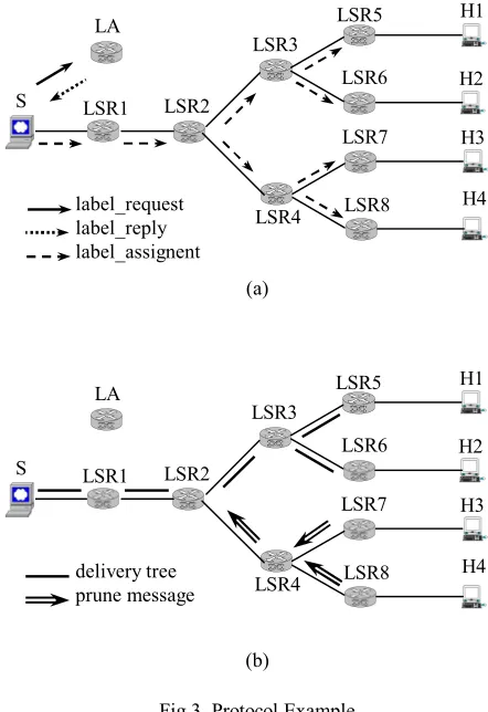
Fig.3 illustrates an example of new mechanism operation. Suppose H1 and H2 are going to join group G. So, send join messages to S. upon receiving join message, S send a
label_request to LA and claim a label. LA send assigned label in a label_reply message. Then, S floods a
label_assignment message in network. Each LSR forward this message by using RPF algorithm and add an entry to its MT table and for each output interface add an entry to OIT table. (Fig. 2)
Each LSR that have no receiver in the group, send a prune message back towards the S and remove (S, G) entry from MT table. Upon receiving prune message, LSR remove pruned interface from OIT and check if all interfaces are removed then send a prune message towards S and remove entry from MT table. (Fig. 3b)
LSR7 and LSR8 send prune message to LSR4. LSR4 remove pruned interfaces from OIT table. All interfaces for this (S, G) removed. Therefore, LSR4 remove (S, G) entry from MT table and then send a prune message to LSR2.
Pruning the unnecessary links in the network results the multicast tree shown in fig.3b.
Fig.4 illustrates the forwarding tables corresponding to LSR3 in Fig.3b. Ij stands for the j'th interface of LSR3. In the
MT of Fig.4, the distribution tree rooted at S for the multicast group addressed by IPG , is labeled with Lg. LSR3 forwards
the corresponding data packets to its output interfaces that are in OIT.
S sends multicast packets to LSR1. LSR1 forward corresponding packets to LSR2. LSR2 do not forward multicast packets to LSR4.
When a host wants to join the group, it sends a join message towards S. If multicast delivery tree for this channel has not been established, message forward to S. Otherwise -multicast delivery tree has been established- message forward towards S. When message reach to a LSR on the tree, LSR look up channel information in MT table and build a message like label_assignment and send towards host. All LSRs in the path towards host update their MT and OIT tables.
H3 want to join the group, therefore send a join message to LSR7. LSR7 send a message to LSR4 and LSR4 forwards message to LSR2. Because LSR2 has the information about group, do not forward message towards S and build a message like label_assignment and send towards H3. LSR4 and LSR7 that are in the path updae their Multicast tables.
When a LSR understand that no receiver attached to it, then, remove (S, G) entry from its tables and send a prune message back towards the S. LSRs in the path towards S, update their tables.
Suppose that H1 leave the group. LSR5 with respect to IGMP protocol, understand no receiver attach to it. LSR5 remove (S, G) entry from its MT table and remove all interfaces for this channel from OIT table. Then, LSR5 send a prune message to LSR3. By receiving prune message, LSR3 remove corresponding interface from its OIT table. LSR3 do not forward prune message, because all interfaces for this channel did not removed.
(a)
[image:3.595.310.531.54.376.2](b)
Fig.3. Protocol Example
Multicast Table
Output Interfaces Label
Input Interface Group Addr.
Source Addr.
Lg
I0
IPG
IPS
Output Interfaces Table
Output Interface Next
I1
I2
Fig.4. Tables of LSR3 in Fig.3b
IV. PERFORMANCE EVALUATION
A. Overhead
In protocols like PIM-DM each LSR should broadcasts its information about network topology, which causes much network overhead. But in proposed mechanism, for creating multicast delivery tree we use flood and prune algorithm once, only when we want to construct delivery tree. So, number of control messages in our method is less than PIM-DM. In comparison with protocols like PIM-DM, our method has a little network overhead.
Because of using different label spaces for unicast and multicast traffic, LSRs use encoding technique that result in additional overheads in routers.
H1 LSR3
LSR5
LSR4 LSR2
LSR6
LSR7
LSR8 LSR1
S
LA
H2
H3
H4 delivery tree
prune message
H1 LSR3
LSR5
LSR4 LSR2
LSR6
LSR7
LSR8 LSR1
S
LA
H2
H3
H4 label_request
B. Memory Consumption
In protocols like PIM-DM and PIM-SM for each output interface some entry maintain in LSRs tables. Each entry containing 32 bit for input label, 8 bit for input interface, 32 bit for output label and 8 bit for output interface. And for every output interface an entry added. Suppose that each multicast session in each LSR has an average of I0 output
interface. So, for each multicast session an 80*I0 bit entry
maintained. If we have an average of S multicast session, so we need S*80*I0 bit memory for maintaining table.
In our method for each multicast tree in network, all LSRs on the tree add an entry to their MT tables. And for each output interface, LSRs add one entry to their OIT table. Because for each output interface we have one entry in OIT table, so by increasing the number of output interfaces of a group, OIT table grow but MT table do not change.
In suggested method for each session we have one entry in MT table that is 112 bit: 32 bit for source address, 32 bit for group address, 8 bit for input interface, 32 bit for input label and 8 bit for pointer to OIT table. Also, in OIT table we have a 16 bit entry for each output interface that contains 8 bit for output interface and 8 bit for pointer to next interface. So, for an average of S multicast session we need S * (112 + 16 * I0)
bit memory. In addition for every multicast session we maintain a 96 bit entry in LA memory. So, we need S * [n * (112 + 16 * I0) + 96] bit memory.
Charts shown below compare suggested method with PIM-DM for 2 and 3 output interfaces.
In above charts we change number of sessions from 5 to 50 for 20 LSRs. As the number of output interfaces increase, the memory used by our method is lesser than other protocols like PIM-DM.
C. Label Consumption
In most methods that so far proposed, multicast consumes labels like unicast. And for constructing multicast tree in network for each hop from source to destination one label used. But, in proposed method we use one and only one label for each multicast session.
Number of labels that can be used are 220 - 16 that is equal
to 1,048,560. We have separated unicast and multicast label spaces from each other. Hence, if a label is consumed in one of them, it has no impact on the other. This means that we divide label space into 2 segments.
V. CONCLUSION AND FUTURE WORKS
We propose a protocol for Mpls multicast. This mechanism can be used in all applications and protocols requiring multicast. A central node called LA is responsible for multicast label assignment and release. Proposed mechanism has no overhead on unicast label space.
It consumes only one label for each multicast tree from multicast label space and no label from unicast label space. Also it has smaller multicast forwarding tables. Therefore, it consumes LSR memory conservatively.
An idea that needs further study is the impact of link failure on the operation of proposed mechanism and the way we treat that.
REFERENCES
[1] E. Rosen, A. Viswanathan, and R. Callon. “Multiprotocol label switching architecture”. IETF RFC3031, January 2001.
[2] S.Deering, D.Estrin, D.Faranacci, V.Jacobson, C.G.Liu, L.Wei, “The PIM Architecture for Wide-Area Multicast Routing”, IEEE/ACM Transactions on Networking, Vol.4, No.2,pp. 153-162, April 1996. [3] S. Keshav, S. Paul, “Centralized Multicast”, 7th International Conference
on Network Protocols, ICNP 1999, Oct. 1999.
[4] D.Waitzman, C.Partridge, S.Deering, “Distance Vector Multicast Routing Protocol”, RFC 1075, Nov. 1988.
[5] D.Ooms, B.Sales, W.Livens, A.Acharya, F.Griffoul, F.Ansari,
“Overview of IP Multicast in a Multi-Protocol Label Switching (MPLS) Environment”, RFC 3353, Aug. 2002.
[6] Dumortier, P., et al., “IP Multicast Shortcut over ATM: A Winner Combination”, IEEE Globecom 99, sydney, Australia.
[7] D.Ooms, W.Livens, “IP Multicast in MPLS Networks”, Proceedings of the IEEE Conference on High Performance Switching and Routing, 2000. [8] A.Ballardie, "Core Based Trees (CBT Version 2) Multicast Routing -
Protocol Specification", RFC 2189, Sep.1997.
[9] D.Farinacci, Y.Rekhter, E.C.Rosen, T.Qian, "Using PIM to Distribute MPLS Labels for Multicast Routes",IETF Draft, draft-faranacci-mpls-multicast-03.txt, Nov. 2000.
[10] A.Acharya, F.Griffoul, F.Ansari, "IP Multicast Support in MPLS", IEEE Proceedings on ATM Workshop, 1999.
[11] Z. Zhang, K. Long, W. Wang, S. Cheng, “The new mechanism for MPLS supporting IP multicast”, The 2000 IEEE Asia-Pacific Conference on Circuits and Systems (APCCAS 2000).
[12] B. Yang and P. Mohapatra, “Edge Router Multicasting with MPLS Traffic Engineering”, IEEE International Conference on Networks (ICON 2002), Aug. 2002.
[13] A. Boudani, B. Cousin, "A New Approach to Construct Multicast Trees in MPLS Networks", Proceedings of the Seventh International Symposium on Computers and Communications (ISCC 2002), pp.913 - 919, July 2002.
Memory Usage 0 5 10 15 20 25 30 35
5 10 15 20 25 30 35 40 45 50
Number of Sessions
K il o B yt e PIM-DM New Approach
Fig.6. Comparison of suggested method with PIM-DM for output interface equal to 3
Memory Usage 0 5 10 15 20 25
5 10 15 20 25 30 35 40 45 50
Number of Sessions
K il o B yt e PIM-DM New Approach
Fig.5. Comparison of suggested method with PIM-DM for output interface equal to 2
M em or y (K il o B yt e) M em or y (K il o B yt e)
Number of Sessions
[14] J. Cho, M. Y. Chung, “A Simple Method for Implementing PIM to ATM Based MPLS Networks”, Proceeding of Ninth IEEE International Conference on Networks, p.p. 362-365, Oct. 2001.
[15] Jong-Moon Chung; Subieta Benito, M.A.; Grace Yoona Cho; Rasiah, P.; Chhabra, H.; “MPLS Multicasting Through Enhanced LDP and RSVP-TE Control”, The 45th Midwest Symposium on Circuits and Systems (MWSCAS-2002), Volume: 3, p.p. 93-96, 2002.
[16] S.Samadian-Barzoki, M.Bag Mohammadi, N.Yazdani, “A Mechanism for MPLS Broadcast and Its Extension for Multicast Dense-Mode Support in MPLS”, Proc. Of ICOIN 2003, Jeju island, Korea, Feb. 2003. [17] S.Samadian-Barzoki, M.Bag Mohammadi, N.Yazdani, “A New Protocol for Baroadcast in MPLS and Its Multicast Dense-Mode Extension”, CSICC 2003, Mashhad, Iran, Feb. 2003 (in Persian).
[18] Jun-Hong Cui, Jinkyu Kim, Aiguo Fei, Michalis Faloutsos, Mario Gerla,