A Q-learning System for Container Marshalling with
Group-Based Learning Model at Container Yard
Terminals
Yoichi Hirashima
Abstract—This paper addresses scheduling problems on the material handling operation at marine container-yard terminals. The layout, removal order and removal distination of contain-ers are simultaneously optimized in order to reduce the waiting time for a vessel. The schedule of container-movements is derived by autonomous learning method based on a new learning model considering container-groups and corresponding Q-Learning al-gorithm. In the proposed method, the layout and movements of containers are described based on the Markov Decision Process (MDP), and a state is represented by a container-layout with a se-lection of a container to be removed or a sese-lection of destination on where the removed container are placed. Then, a state transi-tion arises from a movement, a selectransi-tion of container-destination, or a selectionh of container to be removed. Only the movement takes a cost, and a series of container-movements with selections of destination and order of containers is evaluated by a total amount of costs. As a consequent, the total amount of costs reflects the number of container-movements that is required to achieve desired container-layout. After adequate autonomous learning, the optimum schedule for material han-dling operation can be obtained by selecting a series of container-movements that has the best evaluation. In the problem, the number of container-arrangements increases by the exponential rate with increase of total count of containers. Therefore, con-ventional methods have great difficulties to determine desirable movements of containers in order to reduce the run time for ship-ping.
Keywords: Scheduling, Container Transfer Problem, Q-Learning, Block Stacking, Reinforcement Learning
1
Introduction
In recent years, the number of shipping containers grows rapidly, and in many container yard terminals, increasing throughput of material handling operation becomes important issue as well as decreasing the turnaround times of vessels. Material handling operation for loading containers into a ves-sel is highly complex, and the complexity grows at an expo-nential rate according to the growth of the number of contain-ers, the operation occupy a large part of the total run time of shipping at container terminals. Thus, improving throughput of the material handling operation for loading container on a vessel is one of main interests at marine terminals.
Faculty of Information Science and Technology, Osaka Institute of Tech-nology, 1-79-1, Kita-yama, Hirakata City, Osaka, 573-0196, Japan. Tel/Fax: +86-72-866-5187 Email: [email protected]
monly, materials are packed into containers and each container in a vessel has its own position determined by the destination, weight, owner, and so on [1, 2]. Then, containers have to be loaded into a ship in a certain desired order because they can-not be rearranged in the ship. Therefore, containers must be rearranged before loading if the initial layout is different from the desired layout. Containers carried into the terminal are stacked randomly in a certain area called bay and a set of bays are called yard. The rearrangement process conducted within a bay is called marshalling.
In the problem, the number of stacks in each bay is predeter-mined and the maximum number of containers in a stack is limited. Containers are moved by a transfer crane and the des-tination stack for the container in a bay is selected from the stacks being in the same bay. In this case, a long series of con-tainer movements is often required to achieve a desired layout, and results that are derived from similar initial layouts can be quite different. Although some methods, such as genetic algo-rithm (GA) and multi agent method [3, 4] have been proposed for solveing block stacking problems, environmental models adopted in these methods are different from the marshalling process, and do not apply directly to obtain the desired layout of containers.
reacha-bility to the desired layout in each trial is proposed [8]. In addition, the environmental model considering groups of con-tainers [9] is shown to be effective to improve the learning performance.
This paper proposes a new environmental model integrated in Q-learning method for marshalling plan in order to improve learning performances. The learning process in the proposed method is consisted of two stages: 1. determination of re-arrangement order, 2. selection of destination for removal containers. In both stages, candidates are extended includ-ing all the candidates in conventional methods [8, 9], so that the method can find better marshalling plan as compaired to conventional methods. In addition, Q-values in one stage are referred from the learning algorithm in the other stage. Stages are repeated sequentially in accordance with container move-ments and Q-values are discounted according to the number of container movements, then Q-values reflect the total number of container movements. Consequently, selecting the best Q-values leads the best series of container movements required to obtain a desired layout. Moreover, each rearranged con-tainer is placed into the desired position so that every trial can achieve one of desired layouts. In addition, in the proposed method, each container has several desired positions in the final layout, and the feature is considered in the learning al-gorithm. Thus, the early-phase performances of the learning process can be improved.
Finally, effectiveness of the proposed method is shown by computer simulations for several cases.
[image:2.595.328.510.374.493.2]2
PROBLEM DESCRIPTION
Fig.1 shows an example of container yard terminal. The
ter-Container terminal
Port crane Yard transfer crane
Vessel
Container Yard area
Figure 1: Container terminal
minal consists of containers, yard areas, yard transfer cranes, auto-guided vehicles, and port crane. Containers are carried by trucks and each container is stacked in a corresponding area called bay and a set of bays constitutes a yard area. Each bay has ny stacks thatmy containers can be laden, the number
of containers in a bay isk, and the number of bays depends
on the number of containers. Each container is recognized by an unique name ci
(i = 1;;k). A position of each
container is discriminated by using discrete position numbers,
1;;nymy. Then, the position of the container c i is
de-scribed byx i
(1ik;1x
i
myny), and the state of
a bay is determined by the vector,x=[x 1
; ;x
k ℄.
2.1
Grouping
The desired layout in a bay is generated based on the loading order of containers that are moved from the bay to a ship. In this case, the container to be loaded into the ship can be any-where in the bay if it is on top of a stack. This feature yields several desired layouts for the bay.
2.1.1 Groups in horizontal direction
In the addressed problem, when containers on different stacks are placed at the same height in the bay, it is assumed that the positions of such containers can be exchanged. Fig.2 shows an example of desired layouts, wheremy =ny =3;k=9.
In the figure, containers are loaded in the ship in the descen-dent order. Then, containers c7
;c 8
;c
9 are in the same group
(group1), and their positions are exchanged because the
load-ing order can be kept unchanged after the exchange of po-sitions. In the same way, c4
;c 5
;c
6 are in the group 2, and
c1 ;c
2 ;c
3are in the group
3where positions of containers can
be exchanged. Consequently several candidates for desired layout of the bay are generated from the original desired-layout.
A desired layout (original)
Bay
stack1 stack2 stack3
ny=3
m
y
=
3
Layout candidates for bay
Grouping
group
1
group2
group
3
c7
c7
c7
c7
c7
c7
c8
c8
c8
c8
c8
c8
c9
c9
c9
c9
c9
c9
c4
c4
c4
c4
c4
c4
c5
c5
c5
c5
c5
c5
c6
c6
c6
c6
c6
c6
c1
c1
c1
c1
c1
c1
c2
c2
c2
c2
c2
c2
c3
c3
c3
c3
c3
c3
Figure 2: Layouts for bay
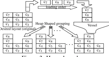
2.1.2 Heap shaped group
In addition to the grouping in the horizontal direction, a “heap shaped group” forny containers at the top of stacks in original
the desired-layout (group1) is generated as follows:
1. ny containers in group
1 can be placed at any stacks if
their height is same as the original one.
2. Each of them can be stacked on otherny 1containers
when both of followings are satisfied:
(a) They are placed at the top of each stack in the orig-inal disired-layout,
(b) The container to be stacked is loaded into the ship before other containers being under the container.
[image:2.595.79.260.489.609.2]Fig.3 depicts an example of heap grouping fork=9;ny=3.
In the figure, containers are loaded into a vessel by the order c9
;c 8
;c 7
;. Then, c
9can be placed on c7and c8, c8can be
placed on c7, so that the number of desired layouts is incresed.
Desired layout (original)
loading order
Heap Shaped grouping Vessel
c1
c1
c1
c1
c2
c2
c2
c2
c3
c3
c3
c3
c4
c4
c4
c4
c5
c5
c5
c5
c6
c6
c6
c6
c7
c7
c7
c7
c7
c7
c8
c8
c8
c8
c8
c8
c9
c9
c9
c9
c9
c9
Figure 3: Heap shaped group
2.1.3 Overlapped group
As the main contribution of the paper, the horizontal groups are extended by overlapping adjacent groups to each other. Groups are overlapped by exchanging members in different groups. When groupjis located on groupi, members being in
the overlapping area, which can be placed in adjacent group are determined by the following rule :
1. A container clin group
j can be placed in groupiif l
sat-isfies
l< ny
2
+(k jny),
wheni > j and loading is conducted with descending
order from ckto c1.
2. A container cr in group
i can be placed in groupj if r
satisfies
r> ny
2
+(k iny),
wheni > j and loading is conducted with descending
order from ckto c1.
Fig.4 shows an example of overlapped group fork=9;ny =
3. In the example, members of group 1 are
fc 9
;c 8
;c 7
g, ones
of group
2
arefc 6
;c 5
;c 4
g, and ones of group 3
arefc 3
;c 2
;c 1
g.
In group
2
c4can be placed in group 3
because c4satisfies the
rule 1, and in group
1
, c3can be placed in group 2
because c3
satisfies the rule 2. When loading is conducted descending order, c4can be placed under c5and c6. c3can be placed on
c1and c2. This feature augments the number of candidates for
optimum layout as shown in the figure.
O
v
er
la
p
p
ed
g
ro
u
p
(E
x
ch
an
g
ea
b
le
)
Candidates of desired layout c1
c1
c1
c1
c2
c2
c2
c2
c3
c3
c3
c3
c4
c4
c4
c4
c5
c5
c5
c5
c6
c6
c6
c6
c7
c7
c7
c7
c8
c8
c8
c8
c9
c9
c9
[image:3.595.80.254.652.747.2]c9
Figure 4: Overlapped group
2.2
Marshalling process
The marshalling process consists of 2 stages: 1 selection of a container to be rearranged, and2 removal of the containers on the selected container in1. After these stages, rearrange-ment of the selected container is conducted. In the stage2, the removed container is placed on the destination stack se-lected from stacks being in the same bay. When a container is rearranged,ny positions that are at the same height in a bay
can be candidates for the destination. In addition,ny
contain-ers can be placed for each candidate of the destination. Then, definingtas the time step,a(t)denotes the container to be
re-arranged attin the stage1.a(t)is selected from candidates
cyi 1
(i
1
=1;;n 2
y)that are at the same height in a desired
layout. A candidate of destination exists at a bottom position that has undesired container in each corresponding stack. The maximum number of such stacks isny, and they can haveny
containers as candidates, since the proposed method consid-ers groups in the desired position. The number of candidates ofa(t) is thusny ny. In the stage 2, the container to
be removed attisb(t)and is selected from two containers
cyi 2
(i
2
= 1;2)on the top of stacks. c
y1 is on the
a(t)and
cy2 is on the destination of
a(t). Then, in the stage2 ,b(t)
is removed to one of the other stacks in the same bay, and the destination stacku(t)at timetis selected from the candidates
u
j
(j =1;;ny 2).a(t)is rearranged to its desired
po-sition after all the cyi 2
s are removed. Thus, a state transition of the bay is described as follows:
x
t+1 =
f(x
t
;a(t)) (stage1) f(x
t
;b(t);u(t)) (stage2)
(1)
wheref()denotes that removal is processed andx
t+1is the
state determined only bya(t);b(t)andu(t)at the previous
statex
t. Therefore, the marshalling plan can be treated as the
Markov Decision Process.
Additional assumptions are listed below:
1. The bay is 2-dimensional.
2. Each container has the same size.
3. The goal position of the target container must be located where all containers under the target container are placed at their own goal positions.
4. kmyny 2my+1
The maximum number of containers that must removed be-fore rearrangement ofa(t)is2my 1because the height of
each stack is limited tomy. Thus, assumption (4) assures the
existence of space for removing all theb(t), anda(t)can be
placed at the desired position from any statex t.
Figure 5 shows 3 examples of marshalling process, where
my =3;ny =5;k=8. Positions of containers are
discrimi-nated by integers1;;15. The first container to be loaded is
c8and containers must be loaded by descendent order until c1
1, a container marked with a
is removed one, and an
ar-rowed line links source and destination positions of removed container. Cases (a),(b) have the same order of rearrangement, c2
;c 7
;c
6, and the removal destinations are different. Whereas,
case (c) has the different order of rearrangement, c8 ;c
2 ;c
7.
When no groups are considered in desired arrangement, case (b) requires 5 steps to complete the marshalling process, and other cases require one more step. Thus, the total number of movements of container can be changed by the destination of the container to be removed as well as the rearrangement order of containers.
If groups are considered in desired arrangement, case (b) achieves a goal layout at step2, case (a) achieves at step3, case (c) achives at step4. If extended groups are considered, cases (a),(b) achive goal layouts at step2 and case (c) achives at step4. Since extended goal layouts include the non-extended goal layouts, and since non-extended goal layouts include a non-grouping goal layout, equivalent or better marshalling plan can be generated by using the extended goal notion as compared to plans generated by other goal notions.
The objective of the problem is to find the best series of move-ments which transfers every container from an initial position to the goal position. The goal state is generated from the ship-ping order that is predetermined according to destinations of containers. A series of movements that leads a initial state into the goal state is defined as an episode. The best episode is the series of movements having the smallest number of move-ments of containers to achieve the goal state.
3
REINFORCEMENT
LEARNING
FOR
MARSHALLING PLAN
3.1
Update rule of Q-values
In the selection ofa, the container to be rearranged, an
eval-uation value is used for each candidate cy i
1 (i
1
= 1;;r,
whereris the number of candidates. In the same way,
eval-uation values are used in the selection of the container to be removedb and its destination u
j
(j = 1;;ny 2).
Candidates of b is c y
i
2 (i
2
= 1;;ny). The evaluation
value for the selection of cyi 1
, cyi 2
and u
j at the state x
are called Q-values, and a set of Q-values is called Q-table. At thelth episode, the Q-value for selecting cyi
1
is defined asQ
1 (l;x;c
yi
1
), the Q-value for selecting c yi
2
is defined as
Q
2 (l;x;c
yi
1 ;c
yi
2
) and the Q-value for selecting u j is
de-fined as Q 3
(l;x;c yi 1 ; c yi 2 ;u j
). The initial value for both
Q
1 ;Q
2 ;Q
3is assumed to be 0.
In this method, a large amount of memory space is required to store all the Q-values referred in every episode. In order to re-duce the required memory size, the length of episode that cor-responding Q-values are stored should be limited, since long episode often includes ineffective movements of container. In the following, update rule of Q
3 is described. When a
se-ries ofnmovements of container achieves the goal statex n
from an initial state x
0, all the referred Q-values from x
0
Initial layout of bay
case (a) case (b) case (c)
Marshalling Step 1 Step 1 Step 1 Step 2 Step 2 Step 2 Step 3 Step 3 Step 3 Step 4 Step 4 Step 4 Step 5 Step 5 Step 5
desired layout for bay positions in a bay
c1 c1 c1
c1 c1 c
1 c1 c1 c1 c1 c1 c1 c1 c1 c1 c1 c1
c2 c2 c2
c2 c2 c
2 c2 c2 c2 c2 c2 c2 c2 c2 c2 c2 c2
c3 c3 c3
c3 c3 c3
c3 c3 c3 c3 c3 c3 c3 c3 c3 c3 c3
c4 c4 c4
c4 c4 c4
c4 c4 c4 c4 c4 c4 c4 c4 c4 c4 c4
c5 c
5 c
5
c5 c
5 c5 c5 c5 c5 c5 c5 c5 c5 c5 c5 c5 c5
c6 c6 c6
c6 c6 c6
c6 c6 c6 c6 c6 c6 c6 c6 c6 c6 c6
c7 c
7 c
7
c7 c
7 c 7 c7 c7 c7 c7 c7 c7 c7 c7 c7 c7 c7
c8 c
8 c
8
c8 c8 c8
c8 c8 c8 c8 c8 c8 c8 c8 c8 c8 c8 9
[image:4.595.315.538.69.282.2]1 2 3 4 5 6 7 8 9 10 11 12 13 14 15
Figure 5: Marshalling process
tox
n are updated. Then, defining
L as the total counts of
container-movements for the corresponding episode,L minas
the smallest value ofL found in the past episodes, andsas
the parameter determining the threshold,Q
3is updated when
L<L
min
+s(s>0)is satisfied by the following equation:
Q
3 (l;x
t
;a(t);b(t);u(t))=
(1 )Q
3
(l 1;x
t
;a(t);b(t);u(t)) +[R+V
t+1 ℄ V t = max y i 1 Q 1 (l;x t ;c y i 1
) (stage)1
max yi 2 Q 2 (l;x t ;a(t);c
yi
2
) (stage)2
(2)
where denotes the discount factor and is the learning
rate. Reward R is given only when the desired layout has
been achieved. L
min is assumed to be infinity at the initial
state, and updated whenL<L
minby the following equation:
L=L
min.
In the selection of b(t), the evaluation value Q 3
(l;x;
a(t);b(t);u j
)can be referred for all theu j
(j=1ny 2),
and the statexdoes not change. Thus, the maximum value of
Q
3
(l;x;a(t);b(t);u j
)is copied toQ 1
(l;x;(t)), that is,
Q
2
(l;x;a(t);b(t))= max
j Q
3
(l;x;a(t);b(t);u j
):
(3)
In the selection ofa(t), the evaluation valueQ 1
(l;x;a(t))is
updated by the following equations:
Q
1 (l;x
t
;a(t))= max y i 1 Q 1 (l;x t ;c y i 1
)+R (stage)1
max yi 2 Q 2 (l;x t ;a(t);c
yi
2
) (stage)2
(4)
In order to select actions, the ”-greedy” method is used.
In the ”-greedy” method, a(t);b(t) and a movement that
have the largest Q 1
(l;x;a(t)); Q 2
(l; x;a(t);b(t)) and Q
3
(l;x;a(t);b(t);u j
) are selected with probability 1
(0<<1), and with probability, a container and a
START
Initialize Q-values
Rearrangea(t)
Rearrangea(t)
Exist freea(t)?
Selecta(t)
Selectb(t)
Save(x;a(t);uj)
Save(x;a(t);u j
)
(UpdateQ3by eq.(3))
(UpdateQ1by eq.(4))
Existb(t)?
Moveb(t)
(UpdateQ 2by eq.(2))
Save(x;a(t);b(t);uj)
(t)
Receive reward Desired layout?
Desired layout?
END yes
yes
yes yes
no no
[image:5.595.82.258.71.324.2]no no
Figure 6: Flowchart of the learning algorithm
3.2
Learning algorithm
By using the update rule, restricted movements and goal states explained above, the learning process is described as follows:
[1]. Count the number of containers being in the goal posi-tions and store it asn
[2]. Ifn=k, go to [10]
[3]. Selecta(t)to be rearranged
[4]. Store(x;a(t))
[5]. Selectb(t)to be removed
[6]. Store(x;a(t);b(t))
[7]. Select destination positionu jfor
b(t)
[8]. Store(x;a(t);b(t);u j
)
[9]. Removeb(t)and go to [5] if anotherb(t)exists,
oth-erwise go to [1]
[10]. Update all the Q-values referred from the initial state to the goal state according to eqs. (2), (3)
A flow chart of the learning algorithm is depicted in Figure 6.
4
SIMULATIONS
Computer simulations are conducted for 2 cases, and learning performances are compared for following two methods:
(A) proposed method using 3 grouping method,
(B) proposed method only using horizontal and heap shaped grouping,
(C) a learning method using eqs. (2)-(4) as the update rule without grouping [8],
(D) method (E) considering original grouping.
(E) a learning method using, eqs. (2),(3) as the update rule, which has no selection of the desired position ofa(t)
[10].
In methods (D),(E), although the stage2 has the same process as in the method (A), the container to be rearranged,a(t), is
simply selected from containers being on top of stacks. The learning process used in methods (D),(E) is as follows:
[1]. The number of containers being on the desired posi-tions is defined ask
B and countk
B [2]. Ifk
B=k, go to [6] else go to [3],
[3]. Selecta(t)by using-greedy method,
[4]. Select a destination ofa(t)from the top of stacks by
using-greedy method,
[5]. Store the state and go to [1],
[6]. Update all the Q-values referred in the episode by eqs. (2),(3).
Since methods (D),(E) do not search explicitly the desired po-sition for each container, each episode is not assured to achieve the desired layout in the early-phase of learning.
In methods (A)-(E), parameters in the yard are set as k =
18;my =ny =6that are typical values of marshalling
envi-ronment in real container terminals. Containers are assumed to be loaded in a ship in descendant order from c18to c1.
Fig-ure 7 shows a desired layout for the two cases, and figFig-ure 8 shows corresponding initial layout for each case. Other pa-rameters are put as=0:8; =0:8;R=1:0;=0:8;s=
15.
Table 1: The best solution of each method for cases 1, 2
Case 1 Case 2
min. ave. min. ave.
counts value counts value
(A) 16 16.90 22 23.00
(B) 18 19.10 23 24.40
Method (C) 34 35.05 35 38.85
(D) 38 46.90 50 64.00
(E) 148 206.4 203 254.0
The container-movement counts of the best solution and its averaged value for each method are described in Table1. Av-eraged values are calculated over 20 independent simulations. Among the methods, method (A) derives the best solution with the smallest container-movements. Therefore method (A) can improve the solution for marshalling as well as learning per-formance to solve the problem.
c1 c2 c3 c4 c5 c6
c7 c8 c9 c10 c11 c12
c13 c14 c15 c16 c17 c18
Figure 7: A desired layout for cases 1,2
c1
c1 c2
c2
c3
c3
c4
c4 c5 c5
c6
c6 c7 c7 c8
c8
c9
c9
c10
c10
c11
c11 c12
c12
c13
c13 c14
c14
c15
c15 c16
c16
c17
c17
c18
c18
Case 1 Case 2
Figure 8: Initial layouts for cases 1,2
5
CONCLUSIONS
A new reinforcement learning system for marshalling plan at container terminals has been proposed. Each container has several desired positions that are in the same group, and the learning algorithm is designed to considering the feature.
In simulations, the proposed method could find solutions that had smaller number of movements of containers as com-pared to conventional methods. Moreover, since the proposed method achieves the desired layout in each trial as well as learns the desirable layout, the method can generate solutions with the smaller number of trials as compared to the conven-tional method.
References
[1] Siberholz, M. B., Golden, B. L., Baker, K., “Using Simu-lation to Study the Impact of Work Rules on Productivity at Marine Container Terminals”,Computers Oper. Res., V.18, N.5, pp. 433–452, 1991.
[2] G¨unther, H.-O., Kim, K. H., Container Terminals and Automated Transport Systems, Springer, pp. 184–206, 2005.
0 1000 2000
20 25
3000 4000 5000 40
45
30 35 50
M
in
im
u
m
st
ep
co
u
n
ts
fo
u
n
d
in
th
e
p
as
t
tr
ia
ls
Trials (D) (C)
[image:6.595.321.532.67.298.2](B) (A)
Figure 9: Performance comparison for case 2
C1
C1 C
2
C2 C3 C4 C3 C4
C5
C5 C6
C6
C7
C7 C8 C8
C9
C9 C
10
C10
C11
C11
C12
C12
C13
C13
C14
C14
C15
C15
C16
C16
C17
C17
C18
C18
Goal obtained by (B) Goal obtained by (A) Figure 10: Final layouts of the best solutions for case 2
[3] Koza, J. R., Genetic Programming : On Programming Computers by means of Natural Selection and Genetics, MIT Press, 1992.
[4] Minagawa, M., Kakazu, Y., “An Approach to the Block Stacking Problem by Multi Agent Cooperation”,Trans.
Jpn. Soc. Mech. Eng. (in Japanese), V.C-63, N.608, pp.
231–240, 1997.
[5] Watkins, C. J. C. H., Dayan, P., “Q-learning”,Machine
Learning, V.8, pp. 279–292, 1992.
[6] Baum, E. B., “Toward a Model of Intelligence as an Economy of Agents”,Machine Learning, V35, pp. 155– 185, 1999.
[7] Hirashima, Y., Iiguni, Y., Inoue, A., Masuda, S., “Q-Learning Algorithm Using an Adaptive-Sized Q-table”,
Proc. IEEE Conf. Decision and Control, pp. 1599-1604,
1999.
[8] Hirashima, Y., Takeda, K., Furuya, O., Inoue, A., Deng, M., “A New Method for Marshaling Plan Using a Re-inforcement Learning Considering Desired Layout of Containers in Terminals”,Preprint of 16th IFAC World
Congress, We-E16-TO/2, 2005.
[9] Hirashima, Y., Ishikawa, N., Takeda, K., “A New Re-inforcement Learning for Group-Based Marshaling Plan Considering Desired Layout of Containers in Port Termi-nals”,International Conference on Networking, Sensing,
and Control, pp. 670-675, 2006.
[10] Motoyama, S., Hirashima, Y., Takeda, K., Inoue A., “A marshalling plan for container terminals based on reinforce-ment learning”,Proc. of Inter. Sympo. on
Ad-vanced Control of Industrial Processes, pp. 631–636,


![Figure 6: Flowchart of the learning algorithmENDnexplained above, the learning process is described as follows:By using the update rule, restricted movements and goal states(t))[1]](https://thumb-us.123doks.com/thumbv2/123dok_us/1316636.661955/5.595.82.258.71.324/figure-flowchart-learning-algorithmendnexplained-learning-described-restricted-movements.webp)
