Component Fatigue Behaviors And Life
Predictions Of A Steering Knuckle Using
Finite Element Analysis
Prof R. L. Jhala, K. D. Kothari, Member IAENG, Dr. S.S. Khandare
Abstract - The paper describes a vehicle steering knuckle undergoing time-varying loadings during its service life. Fatigue behavior is, therefore, a key consideration in its design and performance evaluation. This paper is aimed to assess fatigue life and compare fatigue performance of steering knuckles made from three materials of different manufacturing processes. These include forged steel, cast aluminum, and cast iron knuckles. In light of the high volume of forged steel vehicle components, the forging process was considered as base for investigation. Static as well as baseline cyclic deformation and fatigue properties were obtained and compared.
The paper envisages that in addition, referring a number of load-controlled fatigue component tests conducted for the forged steel and cast aluminum knuckles. Finite element models of the steering knuckles were also analyzed to obtain stress distributions in each component. Based on the results of component testing and finite element analysis, fatigue behaviors of the three materials and manufacturing processes are then compared. The paper concludes with that forged steel knuckle exhibits superior fatigue behavior, compared to the cast iron and cast aluminum knuckles.
1. INTRODUCTION
There has been a strong trend towards the adoption of optimum materials and components in automotive industry. Automotive designers have a wide range of materials and processes to select from; Steel forgings are in competition with aluminum forgings and castings, cast iron, and sintered powder forgings.
Prof R. L. Jhala is an Asst. Prof. and H.O.D, Mech Engg. Dept., V.V. P. Engg. College, Rajkot.( 0281- 2925115, email: aryajhala@yahoo.com)
K. D. Kothari is a Lecturer in Mech. Engg. Dept. ,V.V.P. Engg. College, Rajkot. & Member IAENG (email:
kartik_er@yahoo.com)
Dr. S.S. Khandare is a Principal, B.D. College of Engineering, Sevagram, Varda, Maharashtra.
The steering knuckle, being a part of the vehicle’s suspension system, has alternatives of forging and casting as its base manufacturing process. Since it is connected to the steering parts and strut assembly from one side and the wheel hub assembly from the other, it has complex restraint and constraint conditions and tolerates a combination of loads. In addition, parameters such as internal defects, stress concentrations and gradients, surface finish, and residual stresses can have considerable influence while designing for fatigue. A common practice of fatigue design consists of a combination of analysis and testing. A problem that arises at the fatigue design stage of components is the transferability of data from smooth specimens to the component. The component geometry and surface specifications often deviate from that of the specimen investigated and neither a nominal stress nor a notch factor can be defined in most cases.
A methodology was developed to quantitatively assess fatigue lives of automotive structures and to identify critical and non-damaging areas for design enhancement and weight reduction. The methodology combines load-time history file with results from elastic FEA to estimate fatigue lives. Knuckle strain gage measurements were made for elastic as well as inelastic load ranges.
stress-strain models and multiaxial deformation paths to assess fatigue damage. After the complex load history was reduced to a uniaxial (elastic) stress history for each critical element, a Neuber plasticity correction method was used to correct for plastic behavior. Elastic unit load analysis, using strength of material and an elastic FEA model combined with a superposition procedure of each load point's service history was proposed. These include mean stress effects, load sequence effects above and below the endurance limit, and manufacturing process effects such as surface roughness and residual stresses.
S-N curves under constant amplitude loading and strain-life curves under variable amplitude loading for unnotched and notched specimens and components were compared. It was concluded that the same failure criterion (i.e. first detectable crack), accurate determination of the local equivalent stress or strain, and the same maximum stressed/strained material volume for both the specimens and the components, were preconditions for the transferability of material data obtained from specimens to the component. The maximum stressed/strained material volume appeared to be suitable for taking into account the statistical and mechanical size effects in a relatively simple manner. The objectives of the current study were to compare fatigue performance and assess fatigue life for steering knuckle, a fatigue critical part, made from three materials of different manufacturing processes. Knuckles of three vehicles were selected. These included forged steel knuckle of the rear suspension of a Maruti 800, cast aluminum knuckle of front suspension of Mahindra Scorpio, and cast iron knuckle of the front suspension of a Maruti Omni. Only the forged steel knuckle included the spindle portion. Figure 1 shows the digitized models of the three components.
II DURABILITY COMPARISONS OF COMPONENT
FATIGUE BEHAVIORS AND LIFE PREDICTIONS
Manufacturing process, such as forging or casting, generally determines the strength level and scatter of mechanical properties, but the geometry can suppress the influence of the material. For a complex component geometry where no notch factors could be defined, transferability of material test data could be performed only through local equivalent stresses or strains in the failure critical areas. In this study, the local equivalent stresses and strains corresponding to the experimental loading conditions were obtained by applying
equivalent loads to the simulated finite element models. Since the tests were conducted with a mean load, the modified Goodman equation was used to account for the effect of mean stress:
σa + σm = 1 (1)
σNf Su
Where σa, σNf, σm and Su are alternating stress in
the presence of mean stress, alternating stress for equivalent completely reversed loading, mean stress, and ultimate tensile strength, respectively. The Basquin equation was then used to obtain the fatigue life using the material properties:
σNf = σ’f(2Nf)b (2)
Normally, a surface finish reduction factor is applied to the fatigue strength of a component. However, the fillet of the forged steel knuckle was machined and polished and, therefore, no surface finish factor was applied. For the two cast knuckles, due to the nature of the casting materials and the fact that the defects of a casting material is uniform internally and externally, no surface finish factor was implemented either. In the strain-life approach, the local values of stress and strain at the critical location were used to find fatigue life, according to the Smith-Watson-Topper (SWT) parameter that considers the mean stress effect:
σmaxεaE = (σ’f)2(2Nf)2b + σ’fε’fE(2Nf)b+c (3)
Where σmax is the maximum stress
(σmax = σa + σm) and εa is the strain amplitude.
III FINITE ELEMENT ANALYSIS
Linear and nonlinear static finite element analyses employing Pro Engineer software were conducted on each knuckle. Nonlinear analysis was necessary due to local yielding in most cases, as well as gross yielding in some cases, as mentioned previously. In order to generate precise geometries of the three steering knuckles, a Coordinate Measuring Machine (CMM) was used, with the resulting digitized models as presented in Figure 1.
knuckle, the primary loading was applied to the spindle, and the four suspension and strut holes were restrained.
The analysis showed that changing the location in the spindle length at which the load is applied does not affect the location and magnitude of the stresses at the critical point. To verify the model, other alternatives were analyzed by switching the loading and boundary conditions, and also by releasing any one of the fixed points, to ensure the critical locations remained the same. For the cast aluminum knuckle in service, while the loading is applied to the strut joints through struts, the four hub bolt holes are connected to the wheel assembly. Several trials for boundary conditions were analyzed, including fixing the whole area of the four hub bolt holes, fixing the centerline of the hub bolt holes, only fixing the pair of bolt holes away from the load application point, and fixing two points at the middle area of the hub. It was found that except for the case of fixing the bolt holes, for which the value of stress was lower and the critical location was different, all the other three cases provided approximately similar results. Therefore, the choice of fixing the hub bolt hole-centerlines was selected. For the cast iron knuckle, where the geometry and service conditions are close to the cast aluminum knuckle, similar loading and boundary conditions were applied. While defining a solid mesh for the components, auto meshing feature of the software was employed since it has no geometry restrictions and it could be defined on complicated volumes. The auto mesh generator used an algorithm that minimizes element distortion. 3-D linear tetrahedral solid elements, with global element sizes of 3.81 mm for the forged steel and cast iron knuckles and 5.08 mm for the cast aluminum knuckle were used. Local element sizes of 0.254 mm for the forged steel and 0.635 mm for the cast aluminum and cast iron knuckles were considered at the critical locations (i.e. spindle fillets for forged steel knuckle, and hub bolt holes for cast aluminum and cast iron knuckles). These mesh sizes were obtained based on the convergence of stress and strain energy at certain geometry locations.
A potential source of significant error in fatigue analysis is inaccuracy of stress and strain predictions. Therefore validating the FEA models was critical to this study. To validate the models, values of strains as measured by strain gages in component testing and as predicted using the finite element analysis were compared and are listed in Table 1. The strain gages for the forged steel
knuckle were positioned at the vicinity of the spindle root and the first step fillets, and for the cast aluminum knuckle two gages were positioned at the goose neck of the strut arm and two at the hub bolt holes where the crack initiation was observed during component testing. These locations are identified in Table 1. Depending on the location of the gage, the proper component of the strain obtained from the FE analysis was selected for comparison. The differences between measured and predicted strains obtained for the two knuckles were considered reasonable for the complex knuckle geometries. For the forged steel knuckle, which has a relatively simpler geometry, results of strain calculations from analytical mechanics of materials equation are also listed in Table 1. As can be seen, these results are mostly in between the measured and FEA-predicted strains. The results of the finite element analysis were also checked with regards to symmetry and linearity of the loading in the elastic range. It should be noted that the position of the strain gages and the magnitudes of the applied loads were such that all measured strains were in the elastic range.
The equivalent Von Misses stress contours and critical locations for a typical load value are presented for the three models in Figure 2. The spindle 1st step fillet area for the forged steel knuckle, the hub bolt holes for the cast aluminum knuckle, and the strut arm root and hub bolt hole for the cast iron knuckle, were found to be the areas of high stresses. Von Misses equivalent stresses and strains are used for subsequent fatigue life analysis and comparisons. For the forged steel knuckle, at the highest experimental load level yielding occurred both gross (in the spindle) and locally (at the fillet), whereas for the cast aluminum knuckle at the highest experimental load only local yielding (at the hub bolt hole) occurred.
IV CONCLUSIONS
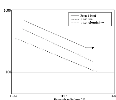
Based on the analyses presented for a steering knuckle, the following conclusions can be made: 1. Better S-N fatigue resistance of the forged steel was observed, as compared with the two cast materials. Long-life fatigue strengths of cast aluminum and cast iron are only 35% and 72% of the forged steel, respectively.
hardening exponent of cast aluminum and cast iron were 46% and 55% of the forged steel, respectively. These indicate higher resistance of the forged steel to cyclic plastic deformation.
3. Comparisons of strain-life fatigue behavior of the three materials indicated that the forged steel provides about a factor of 20 and 4 longer lives in the short-life period compared to the cast aluminum and cast iron, respectively. In the high-cycle period, forged steel resulted in about an order of magnitude longer life than the cast iron, and about a factor of 3 longer lives, compared to the cast aluminum.
4. The differences between measured and FEA predicted strains obtained for the forged steel and cast aluminum knuckles were found to be reasonable for the complex knuckle geometries considered.
5. The S-N predictions were overly conservative, whereas strain comparison of the strain-life prediction curves of the components demonstrated that the forged steel knuckle offers more than an order of magnitude longer life than the cast iron knuckle.
REFERENCES
1. Design of Machine Elements by Dr. Abdul Mubeen
2. Machine Design by Joseph Shigley
3. Gunnarson, S., Ravenshorst, H., and Bergstorm, C. M., “Experience with Forged Automotive Components in Precipitation Hardened Pearlitic- Ferritic Steels,” Fundamentals of Micro alloying Forging Steels, Proceedings, Metallurgical Society of AIME, 1987, pp. 325-338.
4. Lee, S. B., “Structural Fatigue Tests of Automobile Components under Constant Amplitude Loadings,” Fatigue Life Analysis and Prediction, Proceedings, International Conference and Exposition on Fatigue, Goel, V. S., Ed., American Society of Metals, 1986, pp. 177-186.
5. Lee, Y. L., Raymond, M. N., and Villaire, M. A., “Durability Design Process of a Vehicle
Suspension Component,” Journal of Testing and Evaluation, Vol. 23, 1995, pp. 354-363. 6. Beranger, A. S., Berard, J. Y., and Vittori, J. F.,
“A Fatigue Life Assessment Methodology for Automotive Components,” Fatigue Design of Components, ESIS Publication 22, Proceedings of the Second International Symposium on Fatigue Design, FD’95, 5-8 September, 1995, Helsinki, Finland, Marquis, G., Solin, J., Eds., 1997, pp. 17- 25.
7. Conle, F. A. and Chu, C. C., “Fatigue Analysis and the Local Stress-Strain Approach in Complex Vehicular Structures,” International Journal of Fatigue, Vol. 19, No. 1, 1997, pp. S317-S323.
8. Savaidis, G., “Analysis of Fatigue Behavior of a Vehicle Axle Steering Arm Based on Local Stresses and Strains,” Material wissenschaft und Werkstoff technik, Vol. 32, No. 4, 2001, pp. 362, 368.
9. Sonsino, C. M., Kaufmann, H., and Grubisic, V., “Transferability of Material Data for the Example of a Randomly Loaded Forged Truck Stub Axle,” SAE Technical Paper No. 970708 in SAE PT-67, Recent Developments in Fatigue Technology, Chernenkoff, R. A., Bonnen, J. J., Eds., Society of Automotive Engineers, 1997.
10. ASTM Standard E606-92, "Standard Practice for Strain-Controlled Fatigue Testing," Annual Book of ASTM Standards, Vol. 03.01, 1998. 11. ASTM Standard E8-03, "Standard Test
FIGURE 1 FROM LEFT TO RIGHT THE DIGITIZED MODELS OF THE FORGED STEEL, CAST ALUMINUM AND CAST IRON STEERING KNUCKLES.
TABLE 1 COMPARISION OF VALUES OF STRAINS AS MEASURED BY STRAIN GAGES IN COMPONENT TESTING AND AS PREDICTED USING THE FINITE ELEMENT ANALYSIS
[image:5.595.144.477.366.623.2]FOR FORGED STEEL AND CAST ALUMINUM STERRING KNUCKLE WITH THEIR FIGURES
FIGURE 3 S – N CURVES FOR THREE MATERIALS
1000-
True Stress
Am
pli
tude
(M
pa
)
Reversals to Failure, 2Nf
100-
Forged Steel Cast Iron
Cast