Abstract—Digital Virtual Manufacturing (DVM) is technology to facilitate effective product development and agile production by using a digital model to represent the physical and logical schema and the behavior of real manufacturing systems, including products, resources, processes and plant. For successful application of this technology, a digital virtual factory (DVF) functioning in a well-designed and integrated environment is essential. In this research, we constructed a sophisticated, DVF based on kinematic simulations and visualizations of a Korean automotive company’s press shop by analyzing the entire business process and detailed activities of press engineering. We evaluated the geometries, structures, characteristics and motions of all plant and machinery in the press shop. The geometric model and related data of the virtual press shop were built and managed by a modeling standard defined in this paper. The manufacturing press machinery underwent virtual simulation to evaluate the kinematic motions, cycle time and component locations using geometric models and related data in order to perform interference checks and achieve productivity improvements. We expect this virtual press shop to achieve great savings in time and cost in many manufacturing preparation activities in the new car development process of automotive companies.
Index Terms—Digital Virtual Factory, Press Shop, Virtual Manufacturing Simulation
I. INTRODUCTION
Most manufacturing companies face rapidly changing circumstances due to globalized competition and diversified customer demands. Hence, the timely introduction into the market of products capable of meeting the customer needs is an important issue for company survival. This necessitates the establishment of a new paradigm in product development and production [1]. Especially, manufacturing companies are implementing various e-Manufacturing systems for collaborative product development and rapid manufacturing. To realize this implementation, they are conducting research about DVM that includes the product, process and
Manuscript received December 6, 2009. IMECS 2009: International Multi Conference of Engineers and Computer Scientists 2009, Hong Kong 18 – 20 March, 2009.
Seungho Kuk is with Department of Systems Management Engineering, Sungkyunkwan University, Suwon, 440-746, Republic of KOREA (e-mail: [email protected]).
Soon Ill Soh was with Department of Systems Management Engineering, Sungkyunkwan University, Suwon, 440-746, Republic of KOREA. He is now with the AssetMaster Corp., Seoul, 135-280, Republic of KOREA (e-mail: [email protected]).
Soo Min Lim is with Department of Systems Management Engineering, Sungkyunkwan University, Suwon, 440-746, Republic of KOREA (e-mail: [email protected]).
Seon Hwa Joung is with Department of Systems Management Engineering, Sungkyunkwan University, Suwon, 440-746, Republic of KOREA (e-mail: [email protected]).
Sang Do Noh is with Department of Systems Management Engineering, Sungkyunkwan University, Suwon, 440-746, Republic of KOREA (e-mail: [email protected]).
manufacturing system [2]. DVM has been defined as “Technology to realize the rapid and effective product development and manufacturing systems by performing the effective decision making and having the error inspection in advance for the entire production process by using the diverse computer technology such as 3D CAD and simulation based on an integrated digital model that contains the physical and logical schema and the behavior of real manufacturing systems” [3][4].
The General Motor Corporation has a plan to apply virtual manufacturing technology to their manufacturing system as a part of a math-based manufacturing program that started from 1990. This program means that “Every engineer necessitates implementing the manufacturing, assembly system creation, verification, design and operation by using a math-based model before making prototypes” [2]. Particularly, many reports has investigated the effect of applying virtual manufacturing technology to automotive companies such as application deployment and strategy analysis of DVM technology for an overall the business process [5], applying the procedure and results for body shop, paint shop and assembly shop processes [6][7][8], and material analysis and automatic material addressing by using a DVF [4].
An automotive press shop makes panels for the external car shape. The process is divided into two parts: a material production process and a panel production process. In the former, the entered coil is cleaning before processing and then cut into blank panels as needed at blanking press by using upper and lower dies. The blanking line produces proper blank panels that are used for each part of the car by using dies and press machines. In the latter, the designed panels are produced in the press producing line by using dies and press machines. Presswork is the process of producing panels as the raw material is placed between a pair of dies and pressed as the dies are moved up and down.
Applying simulation technology to automotive press fields has evolved remarkably over the last decade from briefly inspecting productivity and cost saving strategies to verifying and modifying concrete design and strategies for optimization. Recently, it has been applied for verifying quality, interference control and analysis of product performance in advance [9]. The following examples demonstrate the application of DVM simulation to press fields. Daimler Chrysler conducted simulation by using OPTRIS press simulation software. Based on the results they improved productivity significantly by defining the optimized process and tools [10]. Volvo constructs a 3D virtual press shop and has introduced eM-Press press simulation software for verification of die and press machine componentry and automation such as layout optimization of dies and press lines, 3D virtual model application, analysis
Construction and Application of a Virtual Press Shop
flow of dies and parts and robots application [11]. Precise Engineering reduced cost by 80% in the start-up phase of production by using PAM-STAMP 2G stamping simulation software based on progressive die strip developed with information provided by PAM-STAMP 2G [12]. Hyundai has reported that press simulation helps them to optimize the die manufacturing process of a side panel’s outer dies. It reduces lead-time by 50% and generates huge cost savings and improved tool and part quality, upfront in the manufacturing process [13].
In this paper, we introduce a methodology of systematically and effectively constructing and applying a DVF for an automotive press shop and present a practical case study. We analyzed and categorized various press shop facilities by establishing and applying a modeling standard based on conducting analysis of the business process for press production. We constructed a digital model of the entire press shop, including press machines, by using 3D-CAD and an applied simulation model capable of analyzing the kinematic motion of press machines.
II. THE BUSINESS PROCESS OF AN AUTOMOTIVE PRESS SHOP
AND A DVF
A. Analysis of the business process of a press shop for constructing a DVF
[image:2.595.297.551.285.683.2]The construction of a DVF requires sufficient time, cost, labor and collaboration among various departments. Therefore, the set up of detailed and stepped application plans is required previously through system engineering approach methods such as analysis of the business process of various departments that are related with the construction of the DVF and the business process re-engineering. Cost savings, reducing lead-time and improving quality should be achieved by conducting each business process organically [14].
Table 1. The task analysis and application of press shop
In this paper, we analyzed the business process of press fields of the objective company and deduced activities that could be applied to DVM technology. We established strategies to apply DVM to press fields by categorizing the required data and the application effect systematically. For this, we used IDEF3 methodology, which is used for process modeling and analysis, and deduced 76 business processes by analyzing the business process. The business process of deduced press fields is mainly focused on the formability of products. So die development, press line analysis and carry-ability are mainly considered.
In this paper, we deduced and analyzed 15 business processes from 76 business processes that could be applied to DVM technology by collaborating with experts from the objective company and researching previous DVM applications based on the above implementation results. The results are presented in (Table 1).
B. Construction of a press DVF and the modeling standard
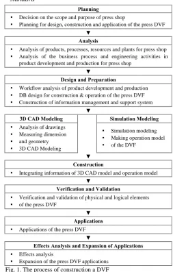
Planning
▪ Decision on the scope and purpose of press shop
▪ Planning for design, construction and application of the press DVF
▼ Analysis
▪ Analysis of products, processes, resources and plants for press shop ▪ Analysis of the business process and engineering activities in
product development and production for press shop
▼
Design and Preparation
▪ Workflow analysis of product development and production ▪ DB design for construction & operation of the press DVF ▪ Construction of information management and support system
▼
3D CAD Modeling Simulation Modeling ▪ Analysis of drawings
▪ Measuring dimension ▪ and geometry
▪ 3D CAD Modeling
▪ Simulation modeling ▪ Making operation model ▪ of the DVF
▼ Construction
▪ Integrating information of 3D CAD model and operation model
▼
Verification and Validation
▪ Verification and validation of physical and logical elements ▪ of the press DVF
▼ Applications
▪ Applications of the press DVF
▼
Effects Analysis and Expansion of Applications
▪ Effects analysis
▪ Expansion of the press DVF applications
Fig. 1. The process of construction a DVF
To apply digital virtual technology to the manufacturing preparation activities of press fields, the integrated information of products, facilities and processes and the engineering results should be managed. Using a reliable 3D-CAD model is essential and the construction and operation of a DVF for the press shop based on this model is needed. DVM is an integrated computer model capable of
Work Application & Effect Required Data
Platform Drawing Virtual Engineering Product
Verification Model Virtual Engineering Product
Proto Drawing Verification Virtual Engineering Product
Method Explanation & Verification
Virtual Engineering
Product Visualization Product
Plan for Inspection area Process Verification Product /Tool
C/F Document Specification Process Verification Product / Tool Verification of Draw Die
Forming ability Virtual Engineering Product
Transfer Line Loading/
Unloading Simulation Process Verification
Product /Facility Pattern Verification &
Improvement Process Verification
Schedule for Training Workers (Facility)
Product/Facility Visualization
Product / Facility
Training Workers Product/Facility
Visualization
Product / Facility Document Panel Inspection
Sheet Process Verification Product
Define Single Rack
Specification Process Verification Product /Rack
Special Rack
Loading-Ability Verification Process Verification Product /Rack Plan for Inspection of
[image:2.595.46.294.495.776.2]providing product and process development, required resources and an integrated environment based on 3D-CAD modeling that is designed by focusing product, process and resource on DVM for conducting math-based engineering before the design phase. Generally, a DVF follows the construction process step by step as shown in (Fig. 1) [3].
It is important to construct and integrate the 3D-CAD model by measuring the facilities size and understanding the blueprints for constructing a DVF. In this paper, we established the modeling standard for constructing a DVF systematically and effectively. Based on this, we analyzed and categorized information for effective modeling.
In this paper, we established and applied the modeling standard for constructing a DVF for systematic and effective modeling and model maintenance. Established the modeling standard was divided into two parts: first, a plant layer standard, a plant modeling file naming standard and a directory structure standard, and second, a library standard for supporting parametric modeling. Use of the modeling standard facilitated effects such as high modularity, maintainability and reusability during the construction of the DVF. The following presents a detailed explanation of the modeling standard established in this paper.
A plant layer standard: It is defined for managing the construction parts and facilities of the constructed DVF more effectively. Each object is contained to designated layers and the model can be utilized by Layer On/Off function of Factory CAD.
A plant modeling file naming standard: It is composed of 22 digits and 8 parts with the meanings of Plant name, Discipline, Area, Floor, Description, Year, Progressing car program and Status.
A directory structure standard: A folder for containing various created files during the DVF construction and by the plant modeling file naming standard. The folders are managed systematically based the on classifying standard for example Plant, Shop and Process.
A library standard for supporting parametric modeling: A parametric modeling library including every construction part and facility for constructing the DVF. It is composed of 6 super classes and sub classes. III. CONSTRUCTION OF AN AUTOMOTIVE PRESS DVF
A. The purpose of constructing a press DVF
In this research, we constructed a press DVF that includes every construction part, facility and press machine for two domestic automotive press shops. The first press shop is exclusively for producing compact size cars and trucks with a productivity of around 210,000 units /year. The second press shop mainly produces mid size cars and SUVs (sports utility vehicle). In addition to the completed car base, the productivity is around 440,000 units /year.
In the case of the automotive press shop, verification by using actual objects is quite difficult because dies and press equipment are very heavy and large. Moreover, practical verification about the inner operation of press machines is needed in advance but verification in practical circumstance is dangerous. Nevertheless, verifying design errors from the early stage of design, workload and layout change and
overcoming expected problems in purchasing new facilities stage concurrently in advance are essential. Therefore, the need to construct and apply press DVF has emerged. The constructing purpose and applying fields are as follows.
Facilities interference checking: In the case of developing and applying new cars to existing facilities, verification of interference checking between existing facilities and newly applying car bodies in advance. Workability check and verification: Analysis and evaluation of workability and suitability between newly producing car bodies and existing facilities.
Production flow analysis: Optimization of press facilities, material addressing, flow strategy and operation programs through simulation.
Work addressing schedule and training workers: collaboration between workers and increasing worker’s understandings through visualization of constructions and facilities of press shop.
B. Construction of an automotive press DVF
a. Objects analysis based on the modeling standard and modeling
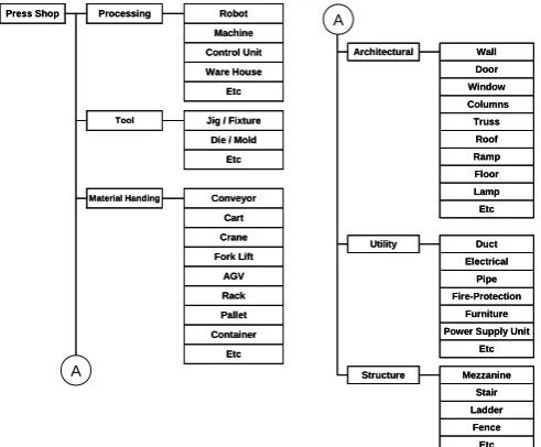
In this research, we defined the plant layers and directory structure that are appropriate for the objective press shop, as shown in (Fig. 2) and (Fig. 3), based on modeling standard. In addition, we defined and applied the library that is appropriate for the objective press shop, as shown in (Fig. 4). The appropriate library for the objective press shop was categorized into 6 super classes, i.e., Processing, Tool, Material Handling, Architectural, Utility and Structure. Super classes composed of sub classes that represent detailed super classes. Robot and Machine, which are sub classes of Processing, were composed of about 40 objects, and Jig and Die, which are sub classes of Tool, were composed of about 10 objects. Conveyor, Crane and Fork Lift, which are sub classes of Material Handling, were composed of about 30 objects.
Fig. 2. The plant layer for the objective press shops
classes of Structure, were composed of about 50 objects.
Fig. 3. The directory structure of the objective press shops
Press Shop Processing Robot Machine Control Unit Ware House
Etc
Tool Jig / Fixture Die / Mold
Etc
Material Handing Conveyor Cart Crane Fork Lift
AGV Rack Pallet Container
Etc Press Shop Processing Robot
Machine Control Unit Ware House
Etc
Tool Jig / Fixture Die / Mold
Etc
Material Handing Conveyor Cart Crane Fork Lift
AGV Rack Pallet Container
Etc
Architectural Wall Door Window Columns Truss
Roof Ramp Floor Lamp Etc
Utility Duct Electrical
Pipe Fire-Protection
Furniture Power Supply Unit
Etc
Structure Mezzanine Stair Ladder
Fence Etc Architectural Wall
Door Window Columns Truss
Roof Ramp Floor Lamp Etc
Utility Duct Electrical
Pipe Fire-Protection
Furniture Power Supply Unit
Etc
Structure Mezzanine Stair Ladder
Fence Etc A
A
Fig. 4. The library structure of the objective press shops
The press parts for conducting a DVF modeling were modeled by using UG NX made by Siemens PLM Software, which was used as an objective company. The constructions and facilities modeling were implemented by using Factory CAD. To model the constructions and facilities, the concept of objects and classes was applied to a DVF based on the definition of object-oriented modeling. We conducted parametric modeling based on the library according to modeling standard [15]. The completed 3D CAD models of the panels and dies, which were modeled by products and dies design departments, were used to guarantee the reliability.
b. Measuring and forming the objects of the press shop
For 3D CAD modeling of the press digital shop, accurate and reliable measurement of the production environment,
including press machines, various facilities, construction structures and safety fence, is essential. The measurement can be divided into 3 parts: measuring the parts of the press machine, measuring the press machine that comprises the parts of the press machine, and measuring the constructions and facilities for positioning the press machines in the shop. In the case of the objective shop, the blueprints for the objects in the shop did not exist and even the dimensions did not exist and were not matched up to the actual dimensions because of the frequent manual modification. Therefore, we used laser distance measuring instruments for conducting the measurement. To reduce the measurement errors, we measured repeatedly and compared the result of the measurement and blueprints for guaranteeing reliability. Moreover, we repeatedly compared the dimensions of the completed 3D model with the dimensions of practical objects for verification of the dimensions.
[image:4.595.304.549.357.502.2]In this research, for more efficient model management and parametric modeling, we composed the dimension table shown in (Fig. 5) and used it to define the specific parts requiring accurate modeling. We thereby increased the reliability of the constructed DVF model by conducting parametric modeling based on the accurately measured dimension table.
Fig. 5. A part of the dimension table of the press shop
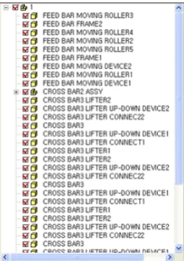
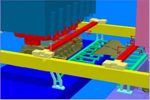
c. Modeling press machines by considering kinematic press simulation
In this paper, we conducted press machine modeling by considering the kinematic simulation. For this, we analyzed every component existing in the press machinery shop and the movement and related construction parts and facilities. Based on the analysis results, we decided the number of parts, which is an important element in the implementation of the kinematic simulation.
[image:4.595.47.293.367.570.2]Fig. 6. The resulting 3D CAD modeling of a press machine
Fig. 7. The structure of 3D CAD modeling of a press machine
Fig. 8. The resulting 3D CAD modeling of the construction of the press shop
C. The construction and application results of a press DVF
(Fig. 9) shows the final result of the construction of the press digital virtual shop of objective automotive company in this paper. The first press shop of this paper was composed of 5 lines: 4 of TR (transfer press) and 1 of BL (blanking press). The second press shop of this paper was composed of 13 lines: 2 of TR, 7 of TD (tandem press) and 4 of BL. According to the modeling result, the TR, TD and BL lines were composed of about 100~150, 150~250 and 150~250 files, respectively. These were dependent on the machinery complexity and the worker skill, but generally it took 4 weeks (20MD) for 1 line construction based on a following standard (8hours/day for a person).
[image:5.595.102.236.248.438.2]We conducted facilities interference checking, material flow analysis, material addressing and press activities verification in advance by integrating and using the completed panels and dies from the design department and the 3D CAD model of the constructed press digital virtual shop, which included press machines, construction parts and facilities. We used virtual manufacturing simulation software such as Tecnomatix eM-Press from Siemens PLM Software, press line simulation (PLS), eM-Plant and Factory CAD/Flow to implement various, math-based engineering solutions for the operation of each press activity of the press shop in the digital environment. (Fig. 10) shows a case of applying the constructed press digital virtual shop model to the material flow analysis of the entire shop.
Fig. 9. The digital virtual press shops
Fig. 10. Material flow analysis using the implemented digital virtual press shop
[image:5.595.305.547.443.596.2] [image:5.595.49.288.462.601.2]conduct accurate verification of the entire movement, shortest path and optimizing transfer time of the press machines in advance.
Fig. 11. Interference checking by virtual manufacturing simulations of the press machine using the implemented digital virtual press shop
IV. CONCLUSION
In this paper, we systematically constructed a press digital virtual shop as a core basis for applying DVM technology to the manufacturing preparation activities in the automotive press shop for the new car development process and introduced applied cases and results. We applied an appropriate modeling standard to the press shop and analyzed the resulting information model. This enabled us to construct the press digital virtual shop systematically and efficiently by measuring the dimension and conducting considered parametric modeling for simulation.
The DVF underwent analysis, construction and maintenance to enable systematic simulation by applying the modeling standard and the considered modeling. The digital model was used for reliable verification and analysis of various purposes in the development of new car processes and modifying and ordering facilities. Moreover, an engineering basis capable of conducting various engineering processes efficiently in practical fields was constructed by using various digital model and information.
Based on the press digital virtual shop constructed in this paper, we conducted facilities interference checking, material flow analysis, material addressing and press activities verification in advance. Virtual manufacturing simulation enabled interference checking between each object such as Die/Cross Bar, Die/Panel, Cross Bar/Slide and Cross Bar/Panel, while visualization enabled the movements of each object to be traced. In addition, this simulation facilitated the extraction of speed, acceleration and position information as basic data for conducting forming analysis.
REFERENCES
[1] Koc, Muammer, Ni, Jun, Lee, Jay and Bandyopadhyay, Pulak,
Introduction of e-Manufacturing, Proceedings of the NAMRC 2003 e-Manufacturingpanel, 2003, 1-12.
[2] Lee, Jang Hui, New product development process of digital
manufacturing role and present condition, Mechanical Journal, 41(10), 2001.
[3] Noh, Sang Do, Ahn, Hyeon Sik and Park, Young-jin, “Virtual Manufacturing for an Automotive Company(IV) - Information Management for a Virtual Factory”, IE Interfaces, 2003, 16(1), 63-69. [4] Lee, Kang Gul, Kang, Hyoung Seok, Noh and Sang Do Noh, “Virtual Manufacturing for an Automotive Company(VI) : Material Addressing and Analysis using Digital Virtual Factory for General Assembly Shop”, IE Interfaces, 2008, 21(1),131-140.
[5] Noh, Sang Do, Lee, Chang Ho and Hahn, Hyung Sang, “Virtual Manufacturing for an Automotive Company(I) - Workflow Analysis and Strategic Planning of Manufacturing Preparation Activities Construction and Operation of a Virtual Body Shop”, IE Interfaces, 2001, 14(2), 120-126.
[6] Noh, Sang Do, Hong, Sung Won, Kim, Duck Young, Sohn, Chang Young and Hahn, Hyung Sang, “Virtual Manufacturing for an Automotive Company( II) - Construction and Operation of a Virtual Body Shop”, IE Interfaces, 2001, 14(2), 127-133.
[7] Noh, Sang Do, Kim, Duck Young and Park, Young-jin, “Virtual Manufacturing for an Automotive Company(III) - Construction and Operation of a Virtual Paint Shop”, IE Interfaces, 2002, 15(4), 356-363.
[8] Park, Tae Keun, Kim, Gun Yeon, Noh, Sang Do and Park, Young Jin, “Virtual Manufacturing for an Automotive Company(V) - Parametric Modeling of the Digital General Assembly Shop using Object-Oriented Methods”, IE Interfaces, 2005, 18(1), 94-103.
[9] Khaldi, Fouad El , Lambriks, Marc and Ling, Dave, New requirements and recent development in sheet metal stamping simulation, ESI GROUP, 2002.
[10] Aberlenc, F., Babeau, J. L., and Jamet, P. (1996), Sheet Metal Stamping for Automotive Applications, Feb 1996.
[11] Faro Inc., (2006), User Story, VOLVO: Press Line Simulation based on 3D scanning. Available:
http://www.faro.com
[12] ESI Group, (2006), Success Story, Precise Engineering: Using PAM-STAMP 2G Stamping Simulation Solution, Precise Engineering Reduces Costs by 80% in Starting Up Progressive Die, S-Precis-01. Available:
http://www.esi-group.com
[13] Park, C. D. and Oh, Se-Wook, “Lead Time Reduction in
Manufacturing Side Panel Outer Dies (A Project Result)”, EuroPAM conference, 2001.
[14] Heo, Jun, Lee, Kang Kul, Noh, Sang Do and Park, Young-Jin, "Web-based Collaborative Process and Material Planning for Automotive General Assembly", Transaction of KSAE, November 2003, Vol. 12, No. 4, pp. 198-206.