http://wrap.warwick.ac.uk
Original citation:
Gerbino, Salvatore, Franciosa, Pasqual and Patalano, Stanislao. (2015) Parametric
variational analysis of compliant sheet metal assemblies with shell elements. Procedia
CIRP, Volume 33 . pp. 340-345.
Permanent WRAP url:
http://wrap.warwick.ac.uk/70005
Copyright and reuse:
The Warwick Research Archive Portal (WRAP) makes this work of researchers of the
University of Warwick available open access under the following conditions.
This article is made available under the Attribution-NonCommercial-NoDerivatives 4.0
(CC BY-NC-ND 4.0) license and may be reused according to the conditions of the
license. For more details see:
http://creativecommons.org/licenses/by-nc-nd/4.0
/
A note on versions:
The version presented in WRAP is the published version, or, version of record, and may
be cited as it appears here.
2212-8271 © 2014 The Authors. Published by Elsevier B.V. This is an open access article under the CC BY-NC-ND license (http://creativecommons.org/licenses/by-nc-nd/4.0/).
Selection and peer-review under responsibility of the International Scientific Committee of “9th CIRP ICME Conference” doi: 10.1016/j.procir.2015.06.077
Procedia CIRP 33 ( 2015 ) 340 – 345
ScienceDirect
9th CIRP Conference on Intelligent Computation in Manufacturing Engineering
Parametric Variational Analysis of Compliant Sheet Metal
Assemblies with Shell Elements
Salvatore Gerbino
a,*, Pasquale Franciosa
b, Stanislao Patalano
ca
University of Molise, DiBT, Via Duca degli Abruzzi, Termoli (CB) 86039, Italy
b
University of Warwick, WMG, CV4 7AL, Coventry,UK
c
University of Naples, Federico II, DII, P.le Tecchio 80, Naples 80125, Italy
* Corresponding author. Tel.: +39-0874-404593. E-mail address: [email protected].
Abstract
One of most demanding tasks in the manufacturing field is controlling the variability of parts as it may affect strongly the deliverability of key characteristics defined at the final (product) assembly level. Current CAT systems offer a good solution to the tolerance analysis/synthesis task, but to handle flexible objects with shape errors more effort is needed to include methods able to capture the elastic behaviour of parts that adds more variability on the final assembly. Usually, sheet metal assemblies require dedicated fixtures and clamps layout to control the gap between parts in the specific location where a join must be placed. Due to the variability of parts the position of clamps can also be varied. The paper describes a FEM-based method able take into account part flexibility and shape error to parametrically analyse sheet metal assemblies by acting on some key parameters to look for the optimal clamp layout that guarantee the gap between parts to be under control after joining parts together. This method offers, with respect to commercial solutions, the ability to model fixtures, clamps and different joint types with no matter on the node positions of the mesh. Locations of such elements are based on the shape functions defined at element (shell) mesh level and modelled as local constraints. So the user can generate a mesh without a previous knowledge of the exact positions of clamps, for example. This allows to conduit a parametric analysis without remeshing the surfaces and with no need to physically model the clamps. An aeronautic case study is described with a four-part assembly riveted on a quite complex fixture by using several clamps.
© 2014 The Authors. Published by Elsevier BV. Selection and/or peer-review under responsibility of Professor Roberto Teti.
Keywords: Sheet metal parts; Compliant assemblies; Free shape variability; Clamp layout optimisation; Shell.
1. Introduction
In the manufacturing context the paradigm "Right First Time" is becoming mandatory in many fields especially where the competitiveness is high such as in the automotive/aeronautic field and consumer goods field as well. To limit failures in the advanced stage of the design process a systematic approach is required to deliver high quality products as soon as possible.
In the last 20 years an increasing interest on variation analysis of compliant assemblies came out in the fields strictly related to the increasing need to better control the variability of both product and process involving flexible components. In the automotive/aeronautic field, about 40% of changes occur after releasing the design, so it is
important not only to start with a good design but also to predict failures by setting process analysis and diagnostic to compensate in time parts and tooling variability [1].
In the contexts where many sheet-metal parts and assemblies are involved, the traditional approach based on the tolerance analysis/synthesis under the hypothesis of rigid body components, also with the support of mature Computer Aided Tolerancing (CAT) tools, is not enough to analyse the behaviour of flexible assemblies. Here more variability comes from the small thickness and the related elasticity, and the free shape of the parts. FEM-based methods are widely described in the literature to predict variations for a given part variation and a given assembly process, and some solutions are also provided to speed up the analysis of batch of parts
© 2014 The Authors. Published by Elsevier B.V. This is an open access article under the CC BY-NC-ND license (http://creativecommons.org/licenses/by-nc-nd/4.0/).
341
Salvatore Gerbino et al. / Procedia CIRP 33 ( 2015 ) 340 – 345
and assemblies to take into account the statistical variability of the product/process.
Usually, sheet metal assemblies require dedicated fixtures to properly locate parts in such a way they can fit well the mating components before assembling them. Particular attention is required for those assemblies that need a tight control of the gap between parts: the shape variation (coming from the manufacturing process), combined with inner flexibility of the part, may require a challenging study of the fixture as well as of the clamp layout. In fact, shape errors related to "actual" parts (instead of the nominal ones usually adopted in the simulation studies) make the analysis more complex. This occurs for example in remote laser welding (RLW) process where, to guarantee a good quality joint, the gap between parts being assembled must be kept within a close range among other specifications. The effect of shape errors is not negligible. The statistical variability of the process also requires that the fixture design and the clamp layout are robust enough to well fit all the batch of the parts [www.rlw-navigator.eu]. For riveted assemblies similar attention is required to look for the "best" location of clamps which a minimum gap along the flanges and a lower reaction on rivets correspond to. In those cases a what-if study can be arranged by automatically changing some key parameters and analysing the effects on the key product characteristics (such as the gap between parts) to achieve.
This paper describes a FEM-based method able to analyse "actual" non-ideal sheet metal assemblies (modelled as shell elements) by changing some key parameters to look for the optimal configuration of clamps that guarantees the gap between parts to be under control after joining parts together. "Actual" is here highlighted because, starting from the nominal model of the parts, their variational shape is accounted by reverse engineering a set of real geometries for each component. This method is implemented in Matlab and offers, with respect to commercial solutions, the ability (I) to include variational models (instead of only nominal ones), and (II) to model fixtures, clamps and different joint types with no matter on the positions of nodes in the mesh. Locations of such elements are based on the shape functions defined at element (shell) mesh level and modelled as local (also non linear) constraints. So the user can generate a mesh to fit the geometry's features without a previous knowledge of the exact positions of clamps, for example. This allows carrying out a parametric study aimed to optimise the clamp layout without locally remeshing the surfaces and with no need to physically model the clamps.
The paper is arranges as follows: section 2 is related to the background about variation analysis of compliant assemblies; section 3 describes the methodology behind the parametric study for clamp layout optimisation;
section 4 describes an application to an industrial case study, while conclusions are reported in the section 5.
2. Background on Variational Analysis of Compliant Assemblies
Variation Simulation Analysis (VSA) is an important step of the manufacturing process because it focuses on the analysis of all sources of variations which may affect the quality of the product and tries to simulate them to predict failures and faults. A specific attention is required for compliant assemblies as they add more variability to the joining process due to the parts' flexibility. In these cases, dimensional and geometrical tolerances alone cannot predict the real shape of the released assembly, as the elastic behaviour of the flexible parts may strongly influence how parts and (sub) assemblies deform. Only in the automotive body structure manufacturing about 37% of all assemblies involve compliant parts [2] and for sure this data needs to be increased looking at the modern manufacturing processes. In [1] the methodology called SOVA, Stream of Variation Analysis, is described to model, analyse and predict dimensional variability of both rigid and compliant assemblies earlier in the design stage of multistage manufacturing processes.
Finite Element Analysis (FEA) is usually adopted to capture the elastic behaviour of the parts.
Focusing the attention on a deterministic assembly with ideal shape parts it is possible, by using commercial FEA software, to run a complex and detailed simulation study including contacts between parts, non-linearities due to local high deformations or material properties, and different assembly sequences.
A real closer analysis should also consider the stochastic variability of the manufacturing process and then hundreds of FE analyses are required, following Monte Carlo approach. This is a very time consuming task solved in [3] with a method able to speed-up the calculation without loosing accuracy in the prediction, while other authors tried to solve it by simplifying the analysis as in [4] where the sensitivity matrix, relating variations at part level with variations at assembly level, is introduced. Similar approach is used in [5-8] for single- and multi-station assembly configurations, also taking into account contact interaction.
to describe form defects with modes analysis, while in [11] the statistical modal analysis (SMA) based on Discrete Cosine Transform (DCT) is proposed. This method, borrowed by the digital imaging field for compression algorithms, is able to decompose shape errors of a stamping part in a sequence of independent error modes and to capture the few main modes that well describe the whole variability of that part. Lindau et al. in [12] adopted Principal Component Analysis (PCA) to statistically described shape errors and look for the principal components that are independent patterns capturing the actual shape variability of a batch of parts. By combining few principal components, a virtual family of deformed parts can be generated for variational assembly simulation. All these methods take advantages from the acquisition of a dense point cloud as for optical scanning devices.
Having the possibility to model the part shape error the fixture design can be accomplished in a better way. The classical 3-2-1 positioning scheme on a fixture usually adopted for rigid parts [13], but also applied to compliant parts [14], cannot fit well to flexible assemblies: here a more general and complex N-2-1 locating scheme is required as described in [15]. These researches anyway only consider ideal parts.
Up to now, there is no systematic methodology for optimising the fixture design with the aim to deliver key characteristics in the final product. Trial and error approach is usually adopted in the industry by starting from an initial configuration that often is set up on internal know how and previous experiences. Fixture elements, locating blocks and clamps are arranged (moved, added or removed) to keep some key characteristics, KCs, under control (contact, gap, flushness, spring-back deviations, etc.), but under the hypothesis of ideal part shape. Computer simulations are then run to see the effects on those KCs. If the KC is not met some adjustments are applied and the simulation re-run several times. However, some industrial applications need a close control of KCs and then the shape error cannot be neglected. This is the case of remote laser welding, as stated before, or riveting processes. In the aerospace field, for example, some parts must be assembled with self-pierce riveting and kept in contact along a large flange to guarantee mechanical strength, fluid dynamic performances and avoiding wind noise. Taking into account shape variability may require repeating this procedure hundreds of times till a solution is reached. The present research is oriented to give a contribution in this direction.
3. Methodology overview
According to previous studies, the variation analysis of compliant assemblies can be performed with a
FEM-based approach and should include: (I) part deformability, (II) non-ideal part modelling, (III) fixture modelling and (IV) clamp layout optimisation. It also should work with a set of variational parts.
Sheet metal parts (with constant thickness) can be simulated with (triangular or quadrilateral) shell elements with 6 degrees of freedom (dof) for each node.
Common assumptions to other similar approaches are: (a) small deformation, (b) elastic behaviour of the part's material, (c) no friction. The last hypothesis, according to the small displacement assumption, is acceptable if no sliding effect occurs and parts come directly in touch, so only the normal displacement is of interest.
FEM-based models require the generation of the mesh from the nominal CAD model. Usually nodes are added on specific locations where boundary conditions (BCs), such as constraints and loads, apply. This may cause the generation of a distorted mesh in closed areas where more BCs are applied, or a local dense mesh is required. Instead, we propose to use the shape functions of the elements to define BCs over the mesh elements, so the mesh can be generated in the best way with no reference to the application of BCs. This functionality will come in handy during the optimisation process where the clamp position will be moved with no matter to the underlying mesh. Avoiding re-meshing is an element that contributes to speed up the analysis.
Penalty method is used as constraint solver (also involved in the contacts calculation). A benchmarking test with commercial software made on static conditions over a set of case studies (not reported here for brevity) demonstrated the robustness of the developed FEM kernel.
343
Salvatore Gerbino et al. / Procedia CIRP 33 ( 2015 ) 340 – 345
and looking for the effects on the gap distribution in several points (rivets' position, for example). A combined Design of Experiments (DoE) and Response Surface Analysis (RSA) approach is set with the aim to look for the best solution in terms of minimum gaps. The following case study will clarify all these steps.
4. Case study
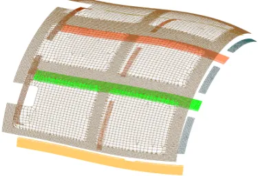
The above methodology has been applied on an assembly of four sheet metal parts coming from aerospace field. It consists in one large bended panel (bounding box: 737x602x227 mm) with three stringers (bounding box: 557x44x37 mm) joined by NAS1097AD4-4 rivets (Fig. 1). The common thickness for all parts made in Aluminium Alloy is 1.02 mm.
[image:5.595.78.284.347.517.2]The panel and the stringers are assembled on the fixture schematically shown in Fig. 1 which highlights all elements adopted to assemble parts together: supports, clamps, NC blocks and rivets location. All fixture elements can be considered rigid. Our attention is focused on stringer #1 that is firstly located on the fixture against the three shaped blocks B1 to B3 and then locked with 5 fixed clamps (FC1 to FC5).
Fig. 1. CAD model of the assembly on the fixture (panel is in transparency mode)
Stringers #2 and #3 are located by means of three NC blocks (NC1 to NC3 for #3 and NC4 to NC6 for #2) and laterally of three more blocks (LB1 to LB3 for #3 and LB4 to LB6 for #2). Then the panel is positioned onto the fixture: elements RC1 to RC3 (in the panel's corners) correspond to the reference clamps that locate and lock the panel on the fixture. Then six one-way clamps (OWC) press the panel against the fixture. Clamps C1 to C3 are the movable elements that hold together both panel and stringer #1 (on both sides) before joining them with 11 rivets (R1 to R11). All geometries have to be input as mesh files with only shell elements. See Fig. 2
for the whole mesh models (also the modelled contact areas with the fixture are shown).
The standard approach is to manually set up the C clamps' position so to reduce the part-to-part gap along the flange, and specifically in the rivets' position. Gaps are checked with a feeler gauge.
The aim of the simulation study is to improve the assembly process with variational components by parametrically changing the position of the C clamps and looking for their optimal location which guarantees the minimum gap in the rivets' position. C clamps can move in the left-right side in a short range (max 50 mm), starting from the assigned initial position defined by the expert user (see Fig. 1). Each clamp's position is parameterised as in equation (1), with P1 and P2 initial
and final position, respectively:
1,2,3 i [0,1], t t P P P
Ci= 1i+( 2i− 1i)* ∈ = (1)
[image:5.595.313.501.388.516.2]The normal orientation of the clamp (direction along which the closing force is applied) changes position by position, due to the shape variability of parts, and it is automatically calculated by the software for each new position of the clamps. The user has just to assign the initial and final positions (as XYZ coordinates from CAD model); then the software is also able to find the correct corresponding points onto the mesh and the related normal vectors.
Fig. 2. Mesh model with shell elements (the panel is in offset position to improve readability)
All clamps are virtually modelled as unilateral constraints acting on a circular area (ø13 mm). No more geometrical details are needed.
scanner (VI-9 by Konica Minolta). The corresponding point clouds (after cleaning data and applying a noise filter in Geomagic 2012) have been used to "deform" the nominal geometries (moving mesh algorithm).
At this stage the virtual assembly model includes: (I) sheet metal parts as variational thin shell mesh models, (II) contact areas fixture-parts, still modelled with shell elements, (III) mechanical properties, (III) boundary constraints, (IV) initial configuration of the movable clamps, and (V) their range of variation. The optimisation problem is conducted by using DoE-RSA methodologies. A full factorial DoE plan involving three factors (movable clamps, C1 to C3) at three levels (initial, intermediate and final position, 1, 2, 3, respectively) is set and for each of 33=27 experiments
the gap between flanges in the rivets' positions is recorded. Thus a 27x11 data matrix is obtained and processed with RSA in Matlab and Minitab.
4.1. Results
We may firstly work on the mean values of the gaps over the whole set of 11 rivets for each combination of clamps' position. In the present study the full quadratic model for the response function best fits all data as the minimum residual is reached with respect to other lower degree models. With the data analysed in Minitab and reported in Table 1 (with C as in equation (1)) the response function Ym appears as in equation (2):
Ym = Į0+Į1*C1+ Į2*C2+Į3*C3+Į4*C12+Į5*C22+
Į6*C3 2
+Į7*C1*C2+Į8*C1*C3+Į9*C2*C3 (2)
Notice from Table 1 that, looking at the column with the p-value and assuming an alpha level of 0.05, the interactions C1*C2 and C1*C3 appear to be statistically not significant on the final response function Ym. This
means that, working on mean values, the interaction of Clamp 1 with Clamp 2 and 3 does not affect the optimal solution, so these terms can also be omitted in (2).
Fig. 4 reports the relationships between Ym and the
pairs of clamp variables in terms of contour plots with the remaining factor set to 0.5. With the present model the minimum Ym for the clamps' position corresponds to
[0.000 0.778 0.434] as shown in Fig. 5.
This optimal solution corresponds to the gap distribution reported in Fig. 6 together with the results of a new FEM run based on that optimal clamps' position.
The very high correlation (0.992) justifies that working on mean value of gaps is here acceptable.
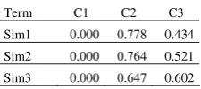
The above analysis can be repeated for more variational part models (related to other measurements) and the final results can be compared to find a more general solution to the clamps' position. Table 2 reports the results of two more analyses compared with the first one. Results from these simulations are in good agreement to each other, thus from Table 1 it can be assumed an average value for clamps' positions.
More points to be monitored during the parametric analysis can also be added, for example to check the gaps' distribution along the whole flange.
We worked on mean values of the gaps over the whole set of 11 rivets. The study can be extended to a multi-objective constrained optimisation problem: a response surface is generated linking the input variables C1, C2 and C3 to the output gap for each single rivet (like in equation (2)), for several combinations of variational parts and imposing a maximum gap. A global optimum solution can be obtained as least square solution of the whole set of equations. Generally specking, the solution of the optimisation problem could not exist: this means that more information could be provided by the designer: for example he/she needs to add more clamps along the flange. With the presented approach this task can be easily accomplished.
5. Conclusions
It has been described a methodology to analyse sheet metal assemblies including part flexibility and part shape variability (i.e. considering non-ideal parts) with the aim to optimise the clamp layout. An assembly with four parts to be riveted and a quite complex fixture has been analysed considering the variability of clamps' position and searching for the best configuration that minimises the gap distribution in some points. This architecture can be extended to a robust global optimisation problem also using the optimisation toolbox by Matlab.
Acknowledgements
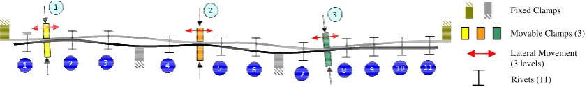
[image:6.595.81.502.73.136.2]This work has been supported by National Project PON01_01268 entitled ‘Digital pattern product development: a pattern driven approach for industrial product design’.
Fig. 3. Example of compliant assembly with variational part models
Fixed Clamps
Movable Clamps (3)
345
[image:7.595.107.485.75.181.2]Salvatore Gerbino et al. / Procedia CIRP 33 ( 2015 ) 340 – 345
Table 1. Estimated regression coefficients for Ym
Term Coef P Constant Į0= 0.51997 0.000
C1 Į1= 0.01360 0.004 C2 Į2= -0.0789 0.000 C3 Į3= 0.02916 0.000 C1*C1 Į4= -0.0232 0.005 C2*C2 Į5= 0.06614 0.000 C3*C3 Į6= 0.03986 0.000 C1*C2 Į7= 0.00584 0.262 C1*C3 Į8= 0.00118 0.817 C2*C3 Į9= -0.0329 0.000
Clamp1 Clamp2 Clamp3
[image:7.595.75.284.215.456.2]opt [0.000] [0.778] [0.434]
Fig. 5. Optimal configuration for Clamps (also the 95% confidence band is shown)
0.000 1.000 2.000
1 3 5 7 9 11
Ga
p
[
m
m
]
Op t RS
FEM
Fig. 6. Gaps for each rivet for the optimal solution
Table 2. Optimal solutions for three variational assemblies
Term C1 C2 C3
Sim1 0.000 0.778 0.434
Sim2 0.000 0.764 0.521
Sim3 0.000 0.647 0.602
References
[1] Ceglarek, D., Huang, W., Zhou, S., Ding, Y., Kumar, R., Zhou, Y., 2009. Time-Based Competition in Multistage Manufacturing: Stream-of-Variation Analysis (SOVA) Methodology - Review. Journal of Flexible Manufacturing Systems 16, pp. 11.
[2] Shiu, B.W., Ceglarek, D., Shi, J., 1996. Multi-Station Sheet Metal Assembly Modeling and Diagnostic. Trans. of NAMRI/SME 24, p. 199.
[3] Xie, K., Wells L., Camelio J.A., Youn, B.D., 2007. Variation Propagation Analysis on Compliant Assemblies Considering Contact Interaction. ASME Journal of Manufacturing Science and Engineering 129, p. 934.
[4] Liu, C.S., Hu, J.S., 1997. Variation Simulation for Deformable Sheet Metal Assemblies Using Finite Element Methods. ASME Journal of Manufacturing Science and Engineering 119, p. 368. [5] Sellem, E., Rivière, A., 1998. Tolerance Analysis of Deformable
Assemblies. ASME Design Engineering Technical Conference, DETC98, Atlanta GA.
[6] Gerbino, S., Patalano, S., Franciosa, P., 2008. Statistical Variation Analysis of Multi-Station Compliant Assemblies based on Sensitivity Matrix. Int. J. Computer Applications in Technology, 33(1), p. 12.
[7] Camelio, J., Hu, S.J., Ceglarek, D., 2003. Modeling Variation Propagation of Multi-Station Assembly Systems with Compliant Parts. Journal of Mechanical Design, 125(4), p. 673.
[8] Dahlström, S., Lindkvist, L., 2007. Variation Simulation of Sheet Metal Assemblies Using the Method of Influence Coefficients with Contact Modelling. ASME Journal of Manufacturing Science and Engineering, 129, p. 615.
[9] Franciosa, P., Gerbino, S., Patalano, S., 2010. Simulation of Variational Compliant Assemblies with Shape Errors based on Morphing Mesh Approach. Int. J. Adv. Manuf. Technol. 53(1-4), p. 47.
[10] Samper, S., Formosa, F., 2006. Form Defects Tolerancing by Natural Modes Analysis. J. Comput. Inf. Sci. Eng. 7(1), p. 44. [11] Huang, W., Liu, J., Chalivendra, V., Ceglarek, D., Kong, Z.,
Zhou, Y., 2014. Statistical modal analysis for variation characterization and application in manufacturing quality control. IIE Trans. 46(5), p. 497.
[12] Lindau, B., Lindkvist, L., Andersson, A., Söderberg, R., 2013. Statistical shape modeling in virtual assembly using PCA-technique. Journal of Manufacturing Systems 32(3), p. 456. [13] Phoomboplab, T., Ceglarek, D., 2008. Process Yield
Improvement through Optimal Design of Fixture Layout in 3D Multi-station Assembly Systems. ASME Trans., Journal of Manufacturing Science and Engineering 130(6) No. 061005. [14] Izquierdo, L.E., Hu, S.J., Jin, R., Jee, H., Shi J., Du, H., 2009.
Robust Fixture Layout Design for a Product Family Assembled in a Multistage Reconfigurable Line. J. Manuf. Sci. Eng. 131(4), No. 041008.
[image:7.595.293.510.226.673.2] [image:7.595.100.261.496.578.2] [image:7.595.125.238.628.678.2]