1
Win Adiyansyah Indra,
1S.M. Najib,
2Adi Saptari,
1Siti Asma Che Aziz,
1M.A. Wong and
1Irianto
1Department of Electronic and Computer Engineering Technology,
Faculty of Electrical and Electronic Engineering Technology,
Universiti Teknikal Malaysia Melaka, Hang Tuah Jaya,
76100 Durian Tunggal, Melaka, Malaysia
2
Department of Industrial Engineering, President University, Bekasi, Indonesia
Abstract: This study investigated the handover planning optimization technique for 5th generation system at selected location, Bukit Beruang, Malacca, Malaysia, based on its varies altitudes and high populated area. By utilizing wireless network design platform, Atoll, added with Global Mapper 15 and Earth Explorer, 99.25% of the total selected zone are in soft handover zone with majority, 63.8% are in softer handover zone. The rest 0.75% are in blank spot zone, no handover due to no signal this is because extreme, varied altitude of terrain, land contour and condition of the area. Repeater and satellite can solve this no signal small zone.
Key words: Altitude, atoll, handover, optimization, zone, signal INTRODUCTION
The modern wireless communication system has begun in the near future in the study of (Raisa et al., 2016). Due to the enormous demand for more capacity, high mobility and superb end to end performance, 5G technology is deployed to meet the demands of many subscribers. However, the spectral frequency resource is finite. Therefore, to provide high data rate, the spectral efficiency must be increased. Besides this, it is very common to reuse frequency spectrum in different cells to increase capacity. Assuming the number of devices will increase to 1000 times the total population of the world by 2020.
The trend pattern in forthcoming mobile networks (5G) has demonstrated a great vary mode from current existing networks, this is due to the main purpose has changed from offering users to connect wirelessly through the Internet to support large numbers of devices and users to seamlessly connect in smart cities by 2020 and beyond (Al-Falahy and Alani, 2017). According to Gohil et al. (2013), although, 4G consists of multi-mode consumer terminals but the unique operating pattern and security support mechanisms in special wireless technologies still remain unknown. The 5G multitier network architecture expect to support the user with simultaneously link on the a lot of wireless technologies and free to switch within them (Sapakal and Kadam, 2013). This should be able to support on merging special flows or connection from different technology to another technology.
Current 4 G LTE (Long Term Evolution) is not sufficient to meet new requirements due to fundamental Evolved Packet Core (EPC) problems consisting of a centralized routing mechanism. Thus, hard work must put on the designation of 5G mobile network architecture. The redesign of 5G network should be able to resolve the EPC problem (Choi et al., 2016). It would be very diverse to use Key Performance Indicators (KPIs) for 5G systems. As in the 4G technology, the trait should not limit the peak data rate and the average requirements for spectral efficiency. Multiple technologies can work independently or in combination to improve transmission efficiency, increase connection limitation and reduce costs for each typical scenario.
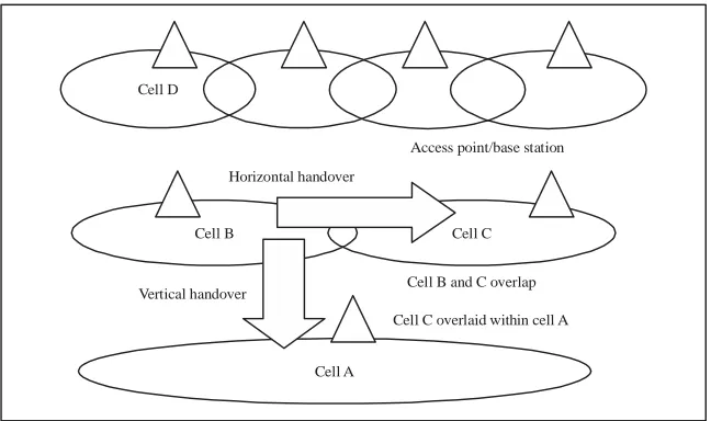
Handover types: The most basic method to explain handover is when an on progress phone call redirected from the existing cell to another new cell. This phenomenon occurs when transferring or moving from one base station coverage to another for the mobile equipment that makes the phone call. The connection of the mobile equipment to the base station become weak and detects there is a data loss, so it forced to swap to the nearest base station area. This shifting action is called handover. It is called a horizontal handover when the handover takes place within the same technology. For instance, among GSM scenarios. When different technologies like UMTS to WLAN are executed, it is mentioned as a vertical handover. The example of horizontal handover and vertical handover are depicted in Fig. 1 (Agrawal et al., 2016).
Corresponding Author:Win Adiyansyah Indra, Department of Electronic and Computer Engineering Technology, Faculty of Electrical and Electronic Engineering Technology,
Cell D
Access point/base station
Horizontal handover
Cell B Cell C
Vertical handover
Cell A
Cell B and C overlap
[image:2.612.155.479.105.297.2]Cell C overlaid within cell A
Fig. 1: Horizontal and vertical handovers
Horizontal handover: Horizontal transfer is the transformation of signal communication from one base station to a base station that provides the same technology as roaming around the client. Horizontal transfer is also based on the transfer of intra-technology. Most of the time a mobile cell host crosses from one cell to a neighboring cell, the network shifts the coverage authority within two nearby base stations automatically and routinely. The handover process occurs efficiently and not gap in communications in a satisfactorily utilized network. Mobile users will not participated in the horizontal handover process. The user will not sense the handover process or realize which base station is currently acting as the support to the mobile. The term of horizontal handover become well know and popular as most extensive research or study has taken in this field in the few past years (Tinkhede and Ingole, 2014).
Vertical handover: Vertical architectures and schemes are going to play a vital role and smooth the way to multi network environments for the emergence of the fourth generation. There are two types of vertical handover that are vertical handover upwards and downwards. A vertical upward transfer drifting to an overlay with a lower bandwidth and larger cell size such as the cellular network of WANs. While, vertical downward transfer roams to an overlay with greater bandwidth and smaller cell size. Overall, vertical downward transfers are less critical in terms of time. The mobile device can always be accessed through the upper overlay and not through the handover (Shurman et al., 2016).
In addition, the vertical handover is way more complicated than horizontal handover due to generally executed between different network domains and
demands a much more troublesome signaling. In vertical handover type along with the power level or received signal strength and other parameters such as frequency and antenna type also need to be taken into consideration.
Hard handover: The term hard handover is defined as there is a “physical” change while the work flows of handover. Take radio connection as an example, the hard handover is consistent but however there will be some time it receiving a short break in the transmission and have to reconnect again. In the 3G network architecture, node B form connection with the User Equipment (UE) and this link usually is a wider telephone network. However, the hard handover of network could eventually happen if there are new connection formed between the node B and UE. During this occasion, the handover of network will be determined by the strength of signal and the strength of broadcast channels.
handover delay or by get rid unnecessary stages to refrain from resource wastage. During the handover process, the mobile station terminate all the Downlink (DL) and Uplink (UL) pockets and thus making the scheme of "break before make". In practical condition, hard handover time should not exceed 50 msec for VOIP and 100 msec for streaming media. This is to ensure mobile service only suffer minimum of data loss and handover delay.
Soft handover: Soft transfer is one of the horizontal transfer that takes place when the end of the user is the coverage area comprising two base stations. The user end can communicate with two neighboring base station when it link to two base station which operate at the same time. In order to have a stable and reliable connection during the handover, it is crucial to set up more than one link. Soft handover rely on the simultaneous link, the link require working on the same channel or frequency. This is because user equipment does not have additional transmitters and receivers that are compulsory when using different frequency values.
When the user equipment and node B undertake a soft handover, the user equipment can include signals from two different node Bs and permeate both signals using RAKE receiver. A RAKE receiver is a type of radio receiver that allows user equipment to set up connection link by the use of concept of Digital Signal Processing (DSP). The main function of DSP is to counter the problems of multipath propagation. “Fingers” also known as the sub-receivers accomplish the problems by providing multipath, each sub-receivers process its components and decode it. The byproducts of sub receivers are than merge together and sum up with a maximum contribution from each path.
Softer handover: Softer handover occurs when new radio links are formed on the similar node B. Certain node B served numerous sectors. When a user equipment mobile, it will simplifying the merging process as it accomplished within the node B and no addition connection further back into network. In term of 3G techno, Universal Mobile Telecommunications Service (UMTS) which serve as a broadband undergo softer handover whenever a user equipment generate signals from two sectors served by the exact same node B (Kumar et al., 2015). Additional condition for the occurrence is sectors overlapping which relate to the multipath propagation resulting from reflections of buildings.
The uplink signals from the two sectors usually despatched to the same RAKE receiver and then fixed to generate an outstanding signal. Whilst for the downlink
receiver make use of the selected de-spreading or descrambling codes to accept the signals. Once the despreading and de-scrambling are done, signals will merge as before.
One of the critical and vital parameters on determines a good quality network is the signal coverage. Signal coverage is the region or area that a signal emitted from a base station with at least maintaining a minimum data transfer rate. After the analysis of network coverage, it is important to know the data rate of each network provider can provide on the particular area. The data rate grades are classified into two groups which are 2G/3G and 4G. For current technology, local network providers can only provide us with maximum 4G data transfer rate. The performance of the data transfer rate is determined by the latency (msec). Latency is the amount of time a message text to traverse a system. A latency test is an instant test which indicates how fast a tiny amount of data can be transfer from phone to the server and back again. A low latency is favorable for a voice or video call over the internet. 5 G is anticipated to support wireless download speeds of more than 1 Gbps in Local Area Network (LAN) and 500 Mbps in Wide Area Network (WAN), approximately 260 times higher than 3 G wireless networks, according to (Edalati and Denidni, 2011). The outstanding download, upload speed and low latency could actually bring the end users to a different realm. The latency of 5G is targeted to be 1 m sec.
MATERIALS AND METHODS
Figure 2 shows the selected location which is the scope area of this 5G handover planning optimization. The covered area is in the region of Bukit Beruang, Melaka or also known as Bear Hill, Malacca. The altitude for Bear Hill is approximately 116.73 m a.s.l. and located at 2.2426°N, 102.2748°E. Bear Hill is an area in Central Melaka District, Melaka, Malaysia. The focus zone of this network planning research carried out from area surrounding Bukit Beruang. The most popular landmark in Bukit Beruang is the Multimedia University. High population is consisted at the Bukit Beruang due to the institution. This located areas is selected as the most suitable location for handover planning. The requirement on network service is higher in the selected location and continuous signal also being a highlighted issue.
Fig. 2: Satellite map of location Bukit Beruang, Melaka configuration the 5G network. Earth explorer is used to explorer the world’s largest collection of images of the Earth’s surfaces. The images are in the forms such as satellite images, elevation and land cover datasets and digitized maps. The digital maps of the Earth Explorer in the format of Digital Raster Graphics (DRGs). The DRG is used to scan image standard series topographic map of a United States Geological Survey (USGS), by including information all map collar. The image within the neat line of the map is geo referenced to the Earth's surface that fits the Universal Transverse Mercator (UTM) projection. Global Mapper 15 is a software package currently developed by Blue Marble Geographics running on Microsoft Windows, a Geographic Information System (GIS). The GIS software is competing with GIS products from ESRI, GeoMedia, Manifold System and MapInfo. Global Mapper handles data from vectors, rasters and elevations, providing viewing, conversion and other general features of GIS. Global Mapper is an affordable and user friendly GIS application that provides access to an unparalleled variety of spatial datasets and provides the right level of functionality to satisfy both experienced GIS professionals and beginners. Forsk Atoll plays a vital role in order to plan the handover in 5G. Atoll is a wireless network design and optimization platform for
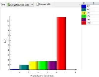
existing network to a new area and no candidate site list is available. The ACP can generate a list of candidate sites by setting an inter-site distance and selecting the zone where ACP is to create sites. The ACP measures the path loss matrices once the candidate site list has been generated and selects the best candidates to use according to the quality and cost objectives defined. Atoll calculates and displays the zones where a handoff can be made in the handoff status coverage prediction. A potential active transmitter, i.e. a transmitter that conform all the criteria for entering the active mobile set, must be available and the service chosen by the user must be available. The prediction of the status transfer to show the number of potential active sender.
One of the features of 5G technology is the high speed data rate. High speed data rate is strongly bonded with the frequency of the wave length. In order to ensure the capability of 5G network to perform, some of the simulations on high frequency application have been done. The 5G network have to ensure no interruption or any data loss (Prados-Garzon et al., 2016). In this simulation, low frequency is set to the range of 700-850 MHz, medium frequency indicates frequency range with 1900-2100 MHz and high frequency is any frequency with higher than 2600 MHz. Overlapping of frequency is a natural phenomenon that often occurs when there are two nearby frequency wave which propagate in opposite directions.
RESULTS AND DISCUSSION
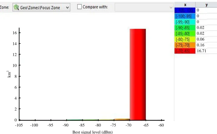
Figure 3 shows the mapping of signal level with all 17 km2 area as Fig. 4 shows the focus area about 98%
which is 16.71 km2 coverage by signal level (DL) more
than or equal to -70 dBm.
[image:5.612.128.486.481.702.2]To optimize the signal level in the area, the topology of 5G network was implemented on the inter-side simulation and altitude simulation. Thus in 5G network simulation, non-uniform planning of base station was used. On high altitude place, the coverage of a base station will be wider and can be reduce the number of base station on that area. The reduction of base station in directory can impact the hand over and the cost of base station. As mention on the above setting section, there are three sites which include of site 3, site 8 and site 26 were change into different frequency which is 1900 MHz. This is to avoid interference between two sites. When two sites are too close, interference will occur and effect the signal level. The other method to encounter the interference is to change the azimuth angle and reduce the coverage area. Due to the high path loss of 5G signal and low coverage area, the setup of base station need to be close enough to provide better signal level. However, if imply and follow the topology as the criteria, the high altitude of Bukit Beruang manage to control the total quality required in this area. Thus no additional number of antenna required if the base stations were all proper manage with optimize topology.
Fig. 3: Signal level of 5G network topology in bukit beruang
16
14
12
10
8
6
4
2
0
-105 -100 -95 -90 -85 -80 -75 -70 -65 -60
Best signal level (dBm)
km
2
Fig. 4: Histogram of signal level based on focus zone
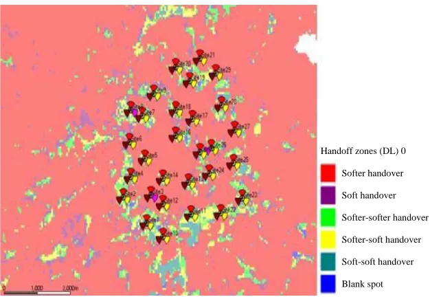
Fig. 5: Handover planning at the selected location Type and number of antennas used needs consideration as well, which should be sufficient to the selected location. In the simulation, the sectoral antenna was choose for each base station. Sectoral antenna is one types of directional antenna. Sectoral antennas are generally used for point-to-multipoint communications at the base transceiver station of wireless communication systems (Indra et al., 2019). It is because the directional antenna happens to be excellent in one direction which are stronger and can reach farther, this mean more clearly, less path loss. The topology in this 5G network simulation is to standardize the height of antenna. The setting was set as any altitude of site below than 50 m, additional 5 m
were add to the antenna. For example in this simulation, Site 6, 10 and 11 found to be low altitude and the height of antenna increase to 35 m to have equal coverage performance as other antennas that were set at height of 30 m and at altitude higher than 50 m.
Figure 5 shows the atoll simulation of handoff zone prediction which used to plan handover status. The handover status is categorized into 6 types, such as softer handover, soft handover, softer-softer handover, softer-soft handover, soft-soft handover and blank spot. Each handover status is represented by different colors. Based on Fig. 6 the occurrence of softer handover is highest compared to other handover status.
Softer handover
Soft handover
Softer-softer handover
Softer-soft handover
Soft-soft handover
Blank spot Handoff zones (DL) 0
Best signal level (dBm)> = -70
Best signal level (dBm)> = -75
Best signal level (dBm)> = -80
Best signal level (dBm)> = -85
Best signal level (dBm)> = -90
Best signal level (dBm)> = -95
Best signal level (dBm)> = -100
Fig. 6: Histogram of handoff zone at the selected location The soft handover is used which mainly refers to feature of OFDM standards of 5G network planning. The soft handover is subdivided into multiple handover status called softer handover, soft handover, softer-softer handover, softer-soft handover, soft-soft handover and no handover. Based on the obtained detail, there is no signal loss within the covered area. According to Radio Network Controller (RNC), traffic handover occurs when the strength of the radio signal drop below a certain parameters.
Through the histogram of handoff zone on Fig. 6, the occurrence of softer handover is the most significant at the focus zone. Softer transmission can be defined as one base station receives two user signals from two adjacent sectors in which it serves. During the propagation of signal waves, some signals were sending from the mobile station to reach the base station. On the intermittent, signals could go through multi path propagation due to building reflections or any natural barriers. The reflected signal treated as multi-path signals and was received during softer handover.
In the uplink path, the received signals at the base station are despatched to the same rake receiver then the maximum ratio combining technique is combined. While downlink direction uses various scrambling codes to distinguish the sectors it process. In summary, it is recommended that the rake receiver's unidentical fingers in the mobile termination imply the allowable de-spreading code on the imparity sector's received signals before combining them all together.
CONCLUSION
By optimizing the related parameters, such as frequencies, antennas, tilt, etc using simulation Software Forsk Atoll, Earth Explorer and Global Mapper 15, 99.25% of the total selected area (Bukit Beruang, Malacca, Malaysia) are in soft handover zone, with majority, 63.8%, are in softer handover zone. The rest 0.75% are in blank spot zone, this is due to extreme, varied altitude of terrain, land contour and condition of the area. It’s not possible to set up base station in or nearby the location. This blank spot zone can be solve by using satellite communication, connect the Base Station and Satellite at each of their gateway.
ACKNOWLEDGEMENT
The researcher would like to thank Universiti Teknikal Malaysia Melaka (UTeM) for sponsoring this work under the Grant PJP/2018/FTK (18B)/S01645.
REFERENCES
Agrawal, A., A. Jeyakumar and N. Pareek, 2016. Comparison between vertical handoff algorithms for heterogeneous wireless networks. Proceedings of the 2016 International Conference on Communication and Signal Processing (ICCSP), April 6-8, 2016, IEEE, Melmaruvathur, India, ISBN:978-1-4673-8549-7, pp: 1375-1373.
10
9
8
7
6
5
4
3
2
1
0
1 2 3 4 5 6 7 8
Potential active transmitters
km
2
1.67
1.74
1.68
Ahmad, R., E.A. Sundararajan, N.E. Othman and M. Ismail, 2017. Handover in LTE-advanced wireless networks: State of art and survey of decision algorithm. Telecommun. Syst., 66: 533-558. Al-Falahy, N. and O.Y. Alani, 2017. Technologies for
5G networks: Challenges and opportunities. IT Prof., 19: 12-20.
Choi, Y.I., J.H. Kim and N.I. Park, 2016. Revolutionary direction for 5G mobile core network architecture. Proceedings of the 2016 International Conference on Information and Communication Technology Convergence (ICTC), October 19-21, 2016, IEEE, Jeju, South Korea, ISBN:978-1-5090-1326-5, pp: 992-996.
Chounos, K., S. Keranidis, A. Apostolaras and T. Korakis, 2019. Fast spectral assessment for handover decisions in 5G networks. Proceedings of the 2019 16th IEEE Annual International Conference on Consumer Communications & Networking (CCNC), January 11-14, 2019, IEEE, Las Vegas, Nevada, USA., ISBN:978-1-5386-5554-2, pp: 1-6. Edalati, A. and T.A. Denidni, 2011. High-gain
reconfigurable sectoral antenna using an active cylindrical FSS structure. IEEE. Trans. Antennas Propag., 59: 2464-2472.
Gohil, A., H. Modi and S.K. Patel, 2013. 5G technology of mobile communication: A survey. Proceedings of the 2013 International Conference on Intelligent Systems and Signal Processing (ISSP), March 1-2, 2013, IEEE, Gujarat, India, ISBN:978-1-4799-0316-0, pp: 288-292.
Gong, F., Z. Sun, X. Xu, Z. Sun and X. Tang, 2018. Cross-tier handover decision optimization with stochastic based analytical results for 5G heterogeneous ultra-dense networks. Proceedings of the 2018 IEEE International Conference on Communications Workshops (ICC Workshops), May 20-24, 2018, IEEE, Kansas City, Missouri, USA., ISBN:978-1-5386-4329-7, pp: 1-6.
Indra, W.A., M.S. Hamid, N.B.M. Yusof, N. A/P Jayraman and H. Rusnandi, 2019. Frequency reuse optimization for OFDMA network. J. Eng. Appl. Sci., 14: 1219-1225.
Indra, W.A., S. A/L Sukumaran, K.A.M. Annuar and Irianto, 2019. Analysis of handover planning in Wideband Code Division Multiple Access (W-CDMA). J. Eng. Appl. Sci., 14: 823-830. Jain, A., E. Lopez-Aguilera and I. Demirkol, 2018.
Improved handover signaling for 5G networks. Proceedings of the 2018 IEEE 29th Annual International Symposium on Personal, Indoor and Mobile Radio Communications (PIMRC), September 9-12, 2018, IEEE, Bologna, Italy, ISBN:978-1-5386-6010-2, pp: 164-170.
Kumar, S., G. Gupta and K.R. Singh, 2015. 5G: Revolution of future communication technology. Proceedings of the 2015 International Conference on Green Computing and Internet of Things (ICGCIoT), October 8-10, 2015, IEEE, Noida, India, pp: 143-147.
Mandour, M., F. Gebali, A.D. Elbayoumy, G.M.A. Hamid and A. Abdelaziz, 2019. Handover optimization and user mobility prediction in LTE femtocells network. Proceedings of the 2019 IEEE International Conference on Consumer Electronics (ICCE), January 11-13, 2019, IEEE, Las Vegas, Nevada, USA., ISBN:978-1-5386-7911-1, pp: 1-6. Miyim, A.M., M. Ismail and R. Nordin, 2014. Vertical
handover solutions over LTE-advanced wireless networks: An overview. Wireless Personal Commun., 77: 3051-3079.
Prados-Garzon, J., O. Adamuz-Hinojosa, P. Ameigeiras, J.J. Ramos-Munoz, P. Andres-Maldonado and J.M. Lopez-Soler, 2016. Handover implementation in a 5G SDN-based mobile network architecture. Proceedings of the 2016 IEEE 27th Annual International Symposium on Personal, Indoor and Mobile Radio Communications (PIMRC), September 4-8, 2016, IEEE, Valencia, Spain, ISBN:978-1-5090-3255-6, pp: 1-6.
Raisa, F., A. Reza and K. Abdullah, 2016. Advanced inter-cell interference management technologies in 5G wireless Heterogeneous Networks (HetNets). Proceedings of the 2016 IEEE Student Conference on Research and Development (SCOReD), December 13-14, 2016, IEEE, Kuala Lumpur, Malaysia, ISBN:978-1-5090-2949-5, pp: 1-4.
Sapakal, M.R.S. and M.S.S. Kadam, 2013. 5G mobile technology. Intl. J. Adv. Res. Comput. Eng. Technol., 2: 568-571.
Shurman, M.M., M.F. Al-Mistarihi and S.A. Nasser, 2012. Hard handover optimization in mobile WiMAX networks. Proceedings of the 5th International Conference on Communications, Computers and Applications (MIC-CCA2012), October 12-14, 2012, IEEE, Istanbul, Turkey, ISBN:978-1-4673-5230-7, pp: 148-153.
Tinkhede, P. and P. Ingole, 2014. Survey of handover decision for next generation. Proceedings of the International Conference on Information Communication and Embedded Systems (ICICES2014), February 27-28, 2014, IEEE, Chennai, India, pp: 1-5.
Yang, J., X. Ji, K. Huang, Y. Chen, X. Xu and M. Yi, 2018. Unified and fast handover authentication based on link signatures in 5G SDN-based HetNet. IET. Commun., 13: 144-152.