1 | 2 1
Preparation and Testing of Metal/Ce
0.80Gd
0.20O
1.90(Metal: Ni, Pd, Pt, Rh, Ru)
Co-Impregnated La
0.20Sr
0.25Ca
0.45TiO
3Anode Microstructures for Solid Oxide
Fuel Cells
Robert Price a, Mark Cassidy a, Jan G. Grolig b, Andreas Mai b and John T. S. Irvine a
a School of Chemistry, University of St Andrews, St Andrews, Fife, KY16 9ST, UK b Hexis AG, Zum Park 5, CH-8404 Winterthur, Switzerland
Abstract
La0.20Sr0.25Ca0.45TiO3 (LSCTA-) is a novel mixed ionic and electronic conductor (MIEC) material
which can act as a potential replacement Solid Oxide Fuel Cell (SOFC) anode ‘backbone’
microstructure, for the current state-of-the-art Ni-based cermet. By impregnating this
‘backbone’ with electrocatalytically active coatings of metal oxides and metallic particles, it is
possible to create high performance SOFC anodes which offer improved redox stability and tolerance to non-optimal fuel gases. Here, we present short-term test data for SOFC containing LSCTA-anode ‘backbones’ impregnated with a variety of catalyst systems including:
Ni/CGO, Pd/CGO, Pt/CGO, Rh/CGO and Ru/CGO. Electrolyte-supported SOFC containing Ni/CGO impregnated anodes showed large reductions in Area Specific Resistance (ASR), in comparison to previous generation research (0.55 Ω cm2 versus 1.2 Ω cm2, respectively).
Exchange of the Ni component, for Pd and Rh, led to much lower ASR of 0.39 Ω cm2 and 0.41
Ω cm2 (in 97 % H
2:3 % H2O, at 900 °C and 0.8 V), respectively. Equivalent circuit fitting of AC
impedance spectra revealed the absence of an anode charge transfer process for the Rh/CGO catalyst system above 875 °C, in comparison to all other systems, identifying this system as a potential replacement for the Ni-based cermet.
Introduction
Solid Oxide Fuel Cells (SOFC) are electrochemical energy conversion devices which generally operate at temperatures >600 °C in order to efficiently oxidise a fuel gas for heat and electricity generation 1. Therefore, this technology is well suited to combined heat and power
(CHP) applications, e.g. in small domestic residences, as well as much larger scale baseload energy supply, in SOFC-based power plants 2.
The vast majority of SOFC make use of the state-of-the-art Ni-based cermet anode, which despite showing high electrocatalytic activity for H2 and syngas oxidation, often exhibits redox
instability, coking in hydrocarbon fuel sources and sulfur poisoning in unprocessed, odourised natural gas supplies 3,4. Therefore, in order to eliminate these undesirable properties, but
retain the high electrocatalytic activity for fuel oxidation, a novel anode material is required.
2 | 2 1
improve the electrocatalytic activity of these materials, the well-established method of catalyst impregnation can be employed to decorate the ionically and electronically conducting ‘backbones’ with oxide coatings and metallic particles 7-12, which play distinct, but
vital, roles within the anode nanostructure.
The 10 % A-site deficient perovskite: La0.20Sr0.25Ca0.45TiO3 (LSCTA-) is a mixed ionic and
electronic conductor (MIEC) which possesses a high bulk electronic conductivity (28-38 S cm -1 at 880 °C-900 °C) for a fully ceramic material 13,14, as well as a high ‘effective conductivity’
(σeff) in screen printed, porous anode ‘backbone’ microstructures (21 S cm-1) 15, at 900 °C. In
addition, LSCTA- possess an oxygen chemical diffusion coefficient of 3.406×10⁻⁷ cm2 s-1, within
one order of magnitude of the oxide-ion conductor: 8YSZ, providing the material with ionic conductivity 16. Previous generation research at HEXIS and the University of St Andrews led to
the first reported all-oxide SOFC tests at both short stack and full HEXIS Galileo 1000 N system scales, with SOFC containing Ni/Ce0.80Gd0.20O1.90 (CGO) impregnated LSCTA- anodes, which are
described elsewhere 12.
Although promising results were obtained, degradation of the anode was highlighted as an area for improvement. Therefore, following on from work carried out by Price et al., on re-optimisation of the LSCTA-anode ‘backbone 15,17, this research focusses on identification and
characterisation of new impregnated catalyst systems which provide higher electrocatalytic activity for H2 oxidation and which may offer improved redox stability, sulfur tolerance and
degradation rates.
Here, we present initial results from SOFC tests carried out using LSCTA-anode ‘backbone’
microstructures impregnated with a CGO coating as well as a range of metallic catalyst particles which culminate in excellent Area Specific Resistances (ASR) for electrolyte-supported SOFC and exhibit substantial improvements in performance in comparison to the previous generations of research, using such an anode catalyst system.
Experimental
A La0.20Sr0.25Ca0.45TiO3 (LSCTA-, Treibacher Industrie AG) anode screen printing ink was
prepared to a 75 wt. % solids loading 15,17, before being printed onto 160 µm 6ScSZ
electrolytes (HEXIS), using a 230 mesh count (per inch) screen with a 1 cm2 square geometry,
and sintered up to 1350 °C for 2 hours in air. Subsequently, 70 wt. % solids loading inks for the cathode active layer, comprising 50:50 wt. % (La0.80Sr0.20)0.95MnO3 (LSM, Praxair Specialty
Ceramics) and 8 mol. % yttria-stabilised zirconia (8YSZ, Daiichi Kigenso Kagaku Kogyo Co. Ltd), and the current collection layer (pure LSM) were prepared using the previously reported preparatory methods 15,17. A functional cathode, of format LSM-YSZ/LSM, was screen printed
3 | 2 1
The sintered LSCTA- anode was then impregnated with ethanol-based nitrate precursor
solutions by applying a droplet of the solution to the surface of the LSCTA-anode ‘backbone’
microstructure and allowing the liquid to completely diffuse into the pores of the electrode. Firstly, a nitrate precursor solution of Ce0.80Gd0.20O1.90 (CGO) was produced from
Ce(NO3)3.6H2O and Gd(NO3)3.6H2O (99 %, Sigma-Aldrich) and was impregnated into the LSCT
A-anode, before being dried at 80 °C and calcined up to 500 °C for 30 minutes. After the required loading of CGO had been obtained, the same procedure was used to add either: Ni, Pd, Pt, Rh or Ru catalyst components. The Ni precursor solution was produced by dissolving Ni(NO3)3.6H2O (99 %, Acros Organics) in ethanol, whilst nitric acid-based solutions of
Pd(NO3)3, H2[Pt(NO3)6], Ru(NO3)3(NO) and Rh(NO3)3 (Johnson Matthey) were diluted with
ethanol to improve their wettability on the LSCTA-anode ‘backbone’ microstructure.
Au mesh and Au wires were attached to the surfaces of electrodes, with small amounts of Au paste (M-9875, Metalor Technologies (UK) Ltd.) for current collection, and fired up to 750 °C in air to improve contacting, for both SOFC and symmetric cells. SOFC were loaded vertically
into a ‘sealless’ setup with alumina felt gas diffusion gaskets, providing a relevant testing environment to that used at HEXIS (with a post-cell combustion zone). SOFC were tested between 800 °C and 900 °C with flow rates of 250 mL min-1 of both compressed air, as an
oxidant, and 97 % H2:3 % H2O, as a fuel. IV curves and AC impedance spectra for SOFC were
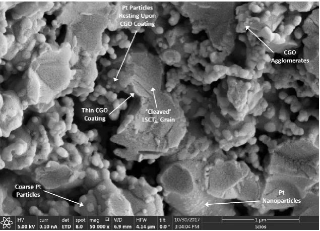
collected using a Solartron SI 1280B Electrochemical Measurement Unit. Post-test Scanning Electron Microscopy was carried out using a FEI Scios Dualbeam FIB-SEM. Simultaneous collection and comparison of secondary electron and backscattered electron micrographs allowed certain features within the anode nanostructure to be identified, based on the differing contrast of regions in the micrograph. For example, CGO layers appeared as brighter layers resting upon darker LSCTA- grains, whilst metallic nanoparticles appeared as much
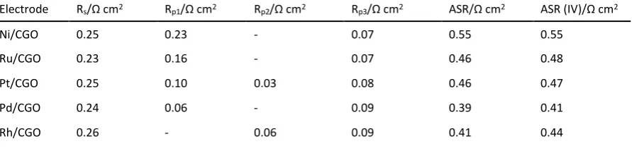
brighter spots. Symmetric cells were clamped between alumina rods with platinum contacts and were placed into a furnace for testing between 800 °C and 900 °C in ambient air, in order to identify and assign cathode responses within AC impedance spectra of full SOFC. AC impedance spectra were collected using a Solartron 1260 Impedance/Gain-Phase Analyser. All AC impedance spectra were subjected to equivalent circuit fitting using the ZView software (V 3.5c, Scribner Associates Inc.) using the models presented in figure 1. Symmetric cells were fitted solely using the model containing two parallel resistor-constant phase element (R-CPE) units (figure 1 a), whilst SOFC were fitted using models with either 2 or 3 parallel R-CPE units (figures 1 a and b), depending upon the number of processes identified within the AC impedance spectra.
LSCTA- was also screen printed onto a 8YSZ electrolyte and sintered up to 1350 °C for 2 hours
to produce a sample, with 46.3 % porosity and 53 µm thickness, for four-point DC conductivity testing. Four Au wires were attached to the surface of the LSCTA- anode with Au paste, in a
4 | 2 1
allowing the resistance and, therefore, ‘effective’ conductivity (σeff) of the porous LSCTA-
thick-film anode 15,18, to be calculated according to equation 1. Here, d = distance between the
inner (voltage) sensing electrodes, R = resistance, l = average length of the electrode contacts and t = thickness of the LSCTA- layer. The sample was placed into a tube furnace before a flow
of 5 % H2/95 % Ar was initiated, at a rate of 100 mL min-1, and the furnace was heated to 900
°C (where p(O2) = 10-19 atm). The sample was allowed to reduce at 900 °C for 18 hours before
data was collected every 60 seconds during cooling to room temperature. Measurements were taken using a Keithley Model 2401 Voltage/Current Source.
𝜎𝑒𝑓𝑓 = 𝑅𝑙𝑡𝑑 [1]
Results and Discussion
Catalyst Loadings
Table I summarises the catalyst systems investigated and weight loadings of catalyst components (with respect to the LSCTA- anode mass) employed in this study. Generally, after
two impregnation cycles, the desired loading of the CGO component was achieved and lay between 13 and 16 wt. %. In order to draw comparison to previous studies carried out by Verbraeken et al. 11,12, the Ni loading was set as 5 wt. %, whilst for the newly studied Pd, Pt,
Rh and Ru-based systems, lower loadings of 2-3 wt. % were desired due to the increased electrocatalytic activity towards H2 oxidation and the comparatively elevated cost to Ni.
Ni/CGO Impregnated SOFC Anode
As previously mentioned, Ni was chosen to provide direct comparison to previous research and to set a baseline performance to which new catalyst systems can be compared. Figure 2 shows the complex plane plot of the AC impedance spectra collected for this SOFC between 800 °C and 900 °C. Two processes are clearly discernible at each temperature; i) a high-frequency process possibly pertaining to charge transfer at the anode (Rp1) and ii) a
low-frequency process most likely representing gas conversion impedance (Rp3). The gas
conversion arc remains independent of temperature 11,19,20, as expected, whilst the anode
charge transfer arc exhibits an increased polarisation and decreased frequency maximum (fmax) as a function of decreasing temperature. Although these processes were also identified
in previous work, the third, mid-frequency process (6-12 Hz) described by Verbraeken et al.
11 is absent for this SOFC. Significantly, at 900 °C the ohmic resistance (R
s), of 0.25 Ω cm2, and
ASR, of 0.55 Ω cm2, show major improvements in comparison to the previous generation of
SOFC (in which the ASR = 1.2 Ω cm2 at the start of the test period) 11, which evidences the
effect of the optimised LSCTA-anode ‘backbone’ microstructure 15,17 as well as the viability of
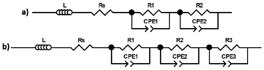
the impregnation method for catalytic activation of the anode microstructure. Figure 3 shows a broken cross-section of the Ni/CGO impregnated LSCTA- anode after testing for
A-5 | 2 1
grains (with any excess CGO forming some clusters within the pores of the microstructure), whilst fine Ni nanoparticles, typically <10 nm, preferentially rest upon the CGO coating. This implies, firstly, that the CGO layer coats the LSCTA- microstructure evenly and, secondly, that
the CGO component stabilises the Ni nanoparticles better than the raw LSCTA- anode
microstructure.
Ru/CGO Impregnated SOFC Anode
Exchanging 5 wt. % of Ni metallic catalyst particles for a Platinum Group Metal (PGM), in this case 3 wt. % of Ru, results in a significant ASR drop of 0.09 Ω cm2 at 900 °C. Figure 4 displays
the complex plane plot of AC impedance spectra collected between 800 °C and 900 °C for the Ru/CGO impregnated SOFC. Once again, at higher temperatures (>850 °C) a simple two-arc spectrum is obtained, relating to the anode charge transfer and gas conversion processes previously described. In addition, though, at temperatures of 825 °C and below, a third, mid-frequency process (Rp2) is visible. The mid-frequency process identified by Verbraeken et al.
was negatively thermally activated and was attributed to surface adsorption and diffusion of reactant species at the anode surface 11. In contrast, the R
p2 process described here is
thermally activated and occurs at higher frequencies than those reported in the literature. This arc relates to cathode charge/oxide transfer processes at the Triple Phase Boundaries (TPB) 21 and will be discussed in greater detail in the following sections. Furthermore, it is
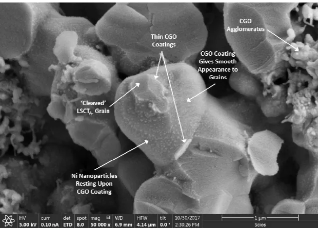
important to note that during collection of the spectra at 825 °C, the refilling of an air compressor led to a temporarily increased flow rate of air to the cathode and additional leakage at the periphery of the SOFC, causing the reversed trend shown in the spectra collected between 850 °C and 825 °C. Figure 5 shows a micrograph of the broken cross-section of the Ru/CGO impregnated LSCTA- anode after testing. In similarity to the Ni/CGO
impregnated anode, the CGO can be observed to form a coating on the LSCTA- grains, in
addition to agglomerates in some areas. However, the Ru particles present in this microstructure are substantially coarser, falling between 20 and 100 nm, resulting in a lower specific surface area available for H2 oxidation. Despite this, the aforementioned drop in ASR
at 900 °C reinforces the fact that the platinum group metals have substantially higher electrocatalytic activity than Ni nanoparticles. The comparatively increased loading of CGO (16 wt. %) in this anode is not expected to contribute significantly to this increase in performance as the majority of H2 oxidation occurs at the TPB between the gas phase, Ru
particles and CGO layer. Therefore, electrocatalytic activity is primarily dependent upon the metallic catalyst loading.
Pt/CGO Impregnated SOFC Anode
Given that Pt is considered to be an ‘industry standard’ catalyst, for applications such as automotive catalytic conversion 22 and in Proton Exchange Membrane Fuel Cells (PEMFC) 23,
its high temperature performance in this co-impregnated LSCTA- SOFC anode was also
6 | 2 1
900 °C for the Pt/CGO impregnated SOFC can be found in figure 6. Only 2 wt. % of Pt was employed in this particular anode, yet it results in the same ASR as the Ru/CGO impregnated SOFC at 900 °C. Interestingly, figure 6 indicates that, at 900 °C, the anode process has decreased in resistance sufficiently to reveal the Rp2 cathode charge transfer process.
However, as previously observed, decreasing the temperature, e.g. to 850 °C for standard HEXIS SOFC operation, causes an increase in the resistance of both the anode and cathode
charge transfer processes, resulting in a ASR of 0.68 Ω cm2 at this temperature, which is not
ideal for longer-term operation in realistic SOFC-based systems. The broken cross-section of the tested Pt/CGO impregnated anode can be found in figure 7. Aside from the ever-present coatings and particles of CGO that can be seen, large Pt particles of 100-150 nm rest upon the anode microstructure. Few nanoscale (<10 nm) particles can be seen on grains while some particles of ~35 nm, can be identified towards the bottom of the micrograph, in similarity to the Ru particles previously described. This, once again, shows that despite the reduced catalytically active surface area, due to coarsened grains of metal, the platinum group metals offer higher electrocatalytic activity towards H2 oxidation.
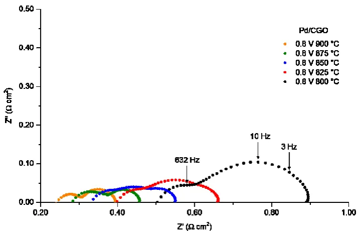
Pd/CGO Impregnated SOFC Anode
Further reduction in ASR is achieved when the impregnated metallic catalyst component employed is 2 wt. % of Pd. At 900 °C a ASR of 0.39 Ω cm2 was achieved for the Pd/CGO
impregnated SOFC, giving a 29 % reduction in comparison to the Ni/CGO impregnated cell and a 15 % reduction in comparison to the ASR of the Ru and Pt/CGO impregnated SOFC. The complex plane plot of AC impedance spectra presented in figure 8 shows that only two processes are isolable at temperatures of 875 °C or higher. Based upon the fmax values
determined for these processes at 900 °C, they may be ascribed to the anode charge transfer (632 Hz) and gas conversion (3 Hz) processes. For the first time, though, the resistance of the anode-related process has dropped below the resistance of the gas conversion process, demonstrating that Pd has substantially higher electrocatalytic activity towards the oxidation of H2, than the previously mentioned metallic catalyst species. In similarity to the AC
7 | 2 1
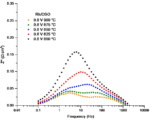
Rh/CGO Impregnated SOFC Anode and LSM-YSZ/LSM Cathode Symmetric Cell
The final catalyst system investigated was the Rh/CGO couple. Rh is of particular interest for sulfur tolerance, based upon reports of tolerance being exemplified for a variety of applications including SOFC, catalysis and fuel reformation 24-26. A 2 wt. % loading was
achieved in the LSCTA- anode of this SOFC making it comparable to all other catalyst loadings
employed. Figure 10 displays the complex plane plot of AC impedance spectra collected between 800 °C and 900 °C for this SOFC, whilst figure 11 shows the AC impedance spectra in Bode format. In similarity to the performance of the Pd/CGO impregnated SOFC, the ASR
achieved was 0.41 Ω cm2; only 0.02 Ω cm2 higher than for the aforementioned SOFC. Also, the
spectrum collected at 900 °C shows a simple two-arc profile, with the higher-frequency process being less resistive than the gas conversion process. Critically, though, the higher frequency process falls into the frequency domain of the cathode charge transfer process, rather than the anode charge transfer process. This is true at both 875 °C and 900 °C, therefore the anode is highly efficient and its polarisation resistance is non-discernible at these temperatures. This is extremely encouraging for the development of impregnated LSCTA- anodes, proving that optimisation of the microstructure and impregnated catalyst
nanostructure can be used to minimise polarisation resistance commonly associated with the anode. In this case, at all temperatures, the cathode is responsible for limitation of performance, especially at 800 °C. The micrograph in figure 12 shows a homogeneous microstructure with CGO coating the LSCTA- grains, as well as particles of CGO formed from
excess material present after coating. Rh particles appear to cover most surfaces of the CGO coating, though it is likely that the sputtered Au coating covers some of the finer Rh nanoparticles. Even so, after testing, particles appear to exhibit a maximum diameter of ~50 nm whilst there is a high population density of particles with diameters of <10 nm, in similarity to the nanostructure of the Pd/CGO impregnated anode. The higher surface area afforded by these fine nanoparticles is one of the main causes of the substantially improved performance achieved using these SOFC with thick-electrolyte supports.
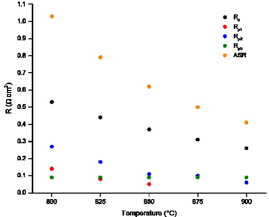
Figure 13 separates the contribution of each polarisation resistance, as well as the ohmic loss, to the overall degradation of ASR at each temperature for the Rh/CGO impregnated SOFC. Considering operation at lower temperatures, the anode charge transfer process eventually becomes visible at 850 °C and its resistance increases with reducing temperature. However, Rp1only contributes 0.14 Ω cm2to the ASR of 1.03 Ω cm2 at 800 °C, whilst the cathode related
Rp2process contributes almost double (0.27 Ω cm2). Symmetric cell testing of a LSM-YSZ/LSM
functional cathode yielded the Bode format plot in figure 14, for comparison of fmax values
determined for the Rp2 process in SOFC testing. At an operating temperature of 900 °C, the
fmax value for the Rp2 process in figure 11 was determined to be 80 Hz, whilst the
mid-frequency process in figure 14 was determined to be 126 Hz. The similarity of the fmax values
and frequency domains confirms that the Rp2 process is a contribution from the cathode
8 | 2 1
amalgam of two (often inseparable) processes of overlapping frequency domain, relating to charge/oxide transfer at the TPB and is commonly observed in the AC impedance spectra of composite LSM-YSZ cathodes 21.
Activation energies (Ea) for each process identified for the Rh/CGO impregnated SOFC are
summarised in table II. Despite the elevated ohmic resistance, due to imperfect contacting of the electrodes, the Ea of 0.38 eV is very similar to that determined in previous work (0.42 eV) 11. Theoretically, R
s should correspond only to the resistance of the electrolyte; in this case
the Ea of the 6ScSZ electrolyte should be 0.78 eV 27, between 1000 °C and 700 °C. However,
the ohmic contribution of the inherently limited electronic conductivity of the LSCT
A-‘backbone’ causes a reduction in Ea, as explained by Verbraeken et al. 11. Figure 15 displays
the Arrhenius plot for the conductivity of the LSCTA-anode ‘backbone’ microstructure, screen
printed on 8YSZ and sintered at 1350 °C for 2 hours. Though semiconductive in nature, two slopes were identified within the Arrhenius plot: i) a high-temperature gradient (520 °C to 900 °C) and ii) a low-temperature gradient (40 °C to 520 °C). The Ea values determined were: 0.10
eV and 0.21 eV, respectively, indicating that small polaron hopping was the responsible mechanism 28-30for electrical conductivity in this anode ‘backbone’ material. Given that the
average Ea of the LSCTA-anode ‘backbone’ (0.16 eV) is so much lower than the theoretical Ea
of 6ScSZ, this provides strong evidence that the observed Ea for Rs (0.38 eV) contains a large
resistive contribution from the LSCTA-anode ‘backbone’.
Furthermore, the anode charge transfer process exhibits a typical activation energy of 0.97 eV, in comparison to 1.03 eV calculated for the Ni/CeO2 impregnated SOFC tested in the
previous generation cells 11, whilst the gas conversion process has a negligible activation
energy of 0.04 eV, as non-electrochemical processes should be independent of temperature. Moreover, the activation energy determined for the mid-frequency process, identified during cathode symmetric cell testing, has been included alongside the Rp2 process. The similarity
between these activation energies (0.79 eV and 0.72 eV, respectively) further confirms that the cathode charge transfer processes are responsible for Rp2, rather than the anode.
Comparison of Performance
Figures 16 and 17 display the complex plane AC impedance spectra (at 0.8 V) and IV curves, respectively, collected for all tested SOFC with co-impregnated LSCTA- anodes at 900 °C. Table
III includes a comprehensive summary of the polarisation resistance data for each SOFC obtained by equivalent circuit fitting using the relevant models presented in figures 1 a and b, in addition to a comparison of ASR values for each SOFC, determined from AC impedance spectra and IV curves. The AC impedance spectra clearly indicate that substantial progress
has been made in catalyst system development in comparison to the ‘standard’ Ni/CGO
impregnate system, with the Pd/CGO and Rh/CGO providing the lowest ASR (0.39 Ω cm2 and
0.41 Ω cm2, respectively). Given the use of a thick, 160 µm electrolyte and the fact that the
9 | 2 1
electrodes and the ohmic resistance contributed by LSCTA-, these ASR are particularly
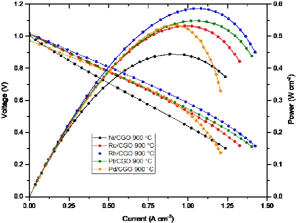
impressive and can be further improved. The IV curves in figure 17 corroborate the AC impedance data, especially in terms of the ASR, with values matching well for all SOFC. The Rh/CGO impregnated SOFC gave the highest peak power density of 0.59 W cm-2. It was
expected that the Pd/CGO impregnated SOFC should give the highest peak power density, however, due to employment of a denser alumina felt gasket, gas diffusion issues limited performance, despite giving the lowest ASR of all SOFC. Finally, the OCV values for these SOFC are lower than the theoretical values due to the use of the ‘sealless’ setup, in which cells are
mounted vertically. Due to the combustion zone established at the periphery of the SOFC, and the large gas flow fields employed in this setup, additional leakage of fuel and oxidant gases can occur at the edge of the SOFC, reducing the p(O2) at the anode and, thus, the p(O2)
gradient between the fuel and air compartments, lowering the OCV.
Conclusions
SOFC comprising metal/CGO co-impregnated La0.20Sr0.25Ca0.45TiO3 anodes, 6ScSZ electrolytes
and LSM-YSZ/LSM cathodes have shown impressive performances during short term testing between 800 °C and 900 °C in test setups similar to those found in the commercial HEXIS SOFC system. The ASR of the Ni/CGO impregnated SOFC has been improved in comparison to the previous generation of cells and the performance of this widely-used impregnate system has been surpassed by exchanging the 5 wt. % Ni metallic catalyst for 2-3 wt. % loadings of the platinum group metals: Pd, Pt, Rh and Ru. Despite the Pd/CGO impregnated SOFC exhibiting the lowest ASR of all SOFC tested (0.39 Ω cm2), the Rh/CGO impregnated SOFC is of particular
interest for further development due to the combination of highest peak power density, a low ASR (0.41 Ω cm2) and the absence of anode-related polarisation resistance above 875 °C.
Acknowledgements
The authors wish to thank Dr J. Andreas Schuler for the support and input provided whilst undertaking this research and Dr Cristian D. Savaniu for helping to carry out conductivity measurements. Additionally, we acknowledge funding from the University of St Andrews and HEXIS AG, as well as the EPSRC Grants: EP/M014304/1 “Tailoring of Microstructural Evolution in Impregnated SOFC Electrodes” and EP/L017008/1 “Capital for Great Technologies”.
References
1. N. Q. Minh, J. Am. Ceram. Soc., 76, 563-588 (1993).
2. S. C. Singhal, in Solid Oxide Fuel Cells: Facts and Figures, J. T. S. Irvine and P. Connor, Editors, p. 1-23, Springer-Verlag, London (2013).
10 | 2 1
4. P. Holtappels and U. Stimming, Handbook of Fuel Cells - Fundamentals, Technology and Applications, W. Vielstich, A. Lamm, and H. A. Gasteiger, Editors, 1st ed., p. 335-354, John Wiley & Sons, Chichester, (2003).
5. P. R. Slater, D. P. Fagg and J. T. S. Irvine, J. Mater. Chem., 7, 2495-2498 (1997)
6. M. C. Verbraeken, T. Ramos, K. Agersted, Q. Ma, C. D. Savaniu, B. R. Sudireddy, J. T. S. Irvine, P. Holtappels and F. Tietz, RSC Adv., 5, 1168-1180 (2015).
7. G. Kim, M. D. Gross, W. Wang, J. M. Vohs, and R. J. Gorte, J. Electrochem. Soc., 155, B360 (2008).
8. G. Corre, G. Kim, M. Cassidy, J. M. Vohs, R. J. Gorte and J. T. S. Irvine, Chem. Mater., 21, 1077-1084 (2009)
9. P. A. Connor, X. Yue, C. D. Savaniu, R. Price, G. Triantafyllou, M. Cassidy, G. Kerherve, D. J. Payne, R. C. Maher, L. F. Cohen, R. I. Tomov, B. A. Glowacki, R. V. Kumar and J. T. S. Irvine,
Adv. Energy Mater., 1800120, 1-20 (2018).
10. T. Ramos, S. Veltzé, B. R. Sudireddy and P. Holtappels, ECS Electrochem. Lett., 3, F5-F6 (2014).
11. M. C. Verbraeken, B. Iwanschitz, A. Mai, and J. T. S. Irvine, J. Electrochem. Soc., 159, F757-F762 (2012).
12. M. C. Verbraeken, B. Iwanschitz, E. Stefan, M. Cassidy, U. Weissen, A. Mai and J. T. S. Irvine, Fuel Cells, 5, 682-688 (2015).
13. A. D. Aljaberi and J. T. S. Irvine, J. Mater. Chem. A, 1, 5868 (2013).
14. A. Yaqub, C. Savaniu, N. K. Janjua, and J. T. S. Irvine, J. Mater. Chem. A, 1, 14189 (2013).
15. R. Price, M. Cassidy, J. A. Schuler, A. Mai, and J. T. S. Irvine, ECS Trans., 78(1), 1385-1395 (2017).
16. A. D. A. Aljaberi, Thesis, University of St Andrews (2013).
17. R. Price, M. Cassidy, J. A. Schuler, A. Mai, and J. T. S. Irvine, ECS Trans., 68(1), 1499-1508 (2015).
18. M. B. Heaney, in Electrical Measurement, Signal Processing, and Displays, J. G. Webster, Editor, CRC Press, Boca Raton (2003).
19. S. Primdahl and M. B. Mogensen, in Proceedings of the Fifth International Symposium on Solid Oxide Fuel Cells (SOFC-V), U. Stimming, S. C. Singhal, H. Tagawa and W. Lehnert,
11 | 2 1
20. S. Primdahl and M. Mogensen, J. Electrochem. Soc., 145, 2431-2438 (1998).
21. M. J. Jørgensen and M. Mogensen, J. Electrochem. Soc., 148, A433 (2001).
22. J. Kašpar, P. Fornasiero, and N. Hickey, Catal. Today, 77, 419-449 (2003).
23. S. Litster and G. McLean, J. Power Sources, 130, 61-76 (2004).
24. M. Cassidy, S. R. Gamble, and J. T. S. Irvine, ECS Trans., 68(1), 2029-2036 (2015).
25. C. Yuan, N. Yao, X. Wang, J. Wang, L. D. Lv and X. Li, Chem. Eng. J., 260, 1-10 (2015).
26. A-M. Azad and M. J. Duran, Appl. Catal. A Gen., 330, 77-88 (2007).
27. A. C. Müller, Thesis, Karlsruhe Institute of Technology (2004).
28. T. Holstein, Ann. Phys. (N.Y.), 8, 343-389 (1959).
29. M. Mogensen, N. M. Sammes, and G. A. Tompsett, Solid State Ionics, 129, 63-94 (2000).
12 | 2 1
Table I. Impregnated catalyst loadings employed in SOFC anodes.
Electrode CGO Loading/Wt. % Metal Loading/Wt. %
Ni/CGO 13 5
Ru/CGO 16 3
Pt/CGO 13 2
Pd/CGO 14 2
[image:12.595.77.515.280.429.2]Rh/CGO 14 2
Table II. Activation energies for processes identified in AC impedance spectra of the SOFC containing the Rh/CGO co-impregnated LSCTA- anode and comparison to the dominant process identified for the LSM-YSZ/LSM cathode.
Process Ea/eV
Rs 0.38
Rp1 0.97
Rp2 0.72
Rp2 (LSM-YSZ/LSM) 0.79
Rp3 0.04
Table III. Summary of RS, Rp and ASR values obtained through equivalent circuit fitting of AC impedance spectra
collected at 0.8 V and 900 °C for all SOFC tested in 97 % H2:3 % H2O and a comparison to ASR values derived from the
slope of the respective IV curves.
Electrode Rs/Ω cm2 Rp1/Ω cm2 Rp2/Ω cm2 Rp3/Ω cm2 ASR/Ω cm2 ASR (IV)/Ω cm2
Ni/CGO 0.25 0.23 - 0.07 0.55 0.55
Ru/CGO 0.23 0.16 - 0.07 0.46 0.48
Pt/CGO 0.25 0.10 0.03 0.08 0.46 0.47
Pd/CGO 0.24 0.06 - 0.09 0.39 0.41
[image:12.595.78.524.474.581.2]13 | 2 1
14 | 2 1
[image:14.595.112.488.74.300.2]Figure 2. Complex plane AC impedance spectra showing the temperature dependence of the processes identified for the SOFC containing a Ni/CGO impregnated LSCTA- anode.
Figure 3. Secondary electron micrograph of a broken cross-section of the Ni/CGO impregnated LSCT A-anode after testing, illustrating a high population density of Ni nanoparticles decorating the
[image:14.595.138.459.356.586.2]15 | 2 1
[image:15.595.112.493.73.301.2]Figure 4. Complex plane AC impedance spectra showing the temperature dependence of the processes identified for the SOFC containing a Ru/CGO impregnated LSCTA- anode.
[image:15.595.136.458.344.576.2]16 | 2 1
[image:16.595.111.491.71.300.2]Figure 6. Complex plane AC impedance spectra showing the temperature dependence of the processes identified for the SOFC containing a Pt/CGO impregnated LSCTA- anode.
[image:16.595.140.458.356.585.2]17 | 2 1
[image:17.595.116.475.68.298.2]Figure 8. Complex plane AC impedance spectra showing the temperature dependence of the processes identified for the SOFC containing a Pd/CGO impregnated LSCTA- anode.
Figure 9. Secondary electron micrograph of a broken cross-section of the Pd/CGO impregnated LSCT
A-anode after testing, clearly illustrating that a CGO coating forms upon the ‘backbone’, which is
[image:17.595.138.459.357.586.2]18 | 2 1
Figure 10. Complex plane AC impedance spectra showing the temperature dependence of the processes identified for the SOFC containing a Rh/CGO impregnated LSCTA- anode.
[image:18.595.110.479.71.298.2] [image:18.595.156.448.356.586.2]19 | 2 1
Figure 12. Secondary electron micrograph of a broken cross-section of the Rh/CGO impregnated LSCT A-anode after testing.
[image:19.595.160.431.359.577.2]20 | 2 1
Figure 14. Bode format AC impedance spectra showing the temperature dependence of the frequencies of processes identified for the LSM-YSZ/LSM cathode symmetric cell. The temperature dependence and fmax value of the dominant process, associated with the cathode, show great similarity to those of the Rp2 process observed during SOFC testing.
[image:20.595.158.442.74.299.2] [image:20.595.149.429.394.618.2]21 | 2 1
Figure 16. Comparative plot of complex plane AC impedance spectra for all SOFC tested at 900 °C and 0.8 V in 97% H2:3% H2O.
[image:21.595.147.446.357.580.2]