Theoretical modeling of airways pressure waveform for
dual-controlled ventilation with physiological pattern
and linear respiratory mechanics
Francesco Montecchia
Laboratorio Sperimentale Policentrico di Ingegneria Medica, Dipartimento di Ingegneria Civile, Università degli Studi di Roma “Tor Vergata”, Rome, Italy.
Email:[email protected]
Received 13 January 2011; revised 28 March 2011; accepted 7 April 2011.
ABSTRACT
The present paper describes the theoretical treat-ment performed for the geometrical optimization of advanced and improved-shape waveforms as air-ways pressure excitation for controlled breathings in dual-controlled ventilation applied to anaesthe-tized or severe brain injured patients, the respira-tory mechanics of which can be assumed linear. Advanced means insensitive to patient breathing activity as well as to ventilator settings while im-proved-shape intends in comparison to conventional square waveform for a progressive approaching to-wards physiological transpulmonary pressure and respiratory airflow waveforms. Such functional fea- tures along with the best ventilation control for the specific therapeutic requirements of each patient can be achieved through the implementation of both diagnostic and compensation procedures ef-fectively carried out by the Advance Lung Ventila-tion System (ALVS) already successfully tested for square waveform as airways pressure excitation. Triangular and trapezoidal waveforms have been considered as airways pressure excitation. The sults shows that the latter fits completely the re-quirements for a physiological pattern of endoal-veolar pressure and respiratory airflow waveforms, while the former exhibits a lower physiological be-haviour but it is anyhow periodically recommended for performing adequately the powerful diagnostic procedure.
Keywords:Mathematical Modeling; Mechanical Ventilation; Controlled Breathing; Pressure and Airflow Waveforms; Respiratory Mechanics; Tidal and Minute Volumes
1. INTRODUCTION
The clinical applications of assisted/controlled ventila-tion are mainly devoted to patients treated with anaes-thesia or in Intensive Care Units or affected by the res-piratory insufficient syndrome [1-3].
When spontaneous breathing of such patients is absent or forbidden for the entire time of treatment, controlled ventilation is required. The respiratory pattern during controlled ventilation shows only controlled breathings,
i.e. breathings for which the control of lung ventilation is
completely carried out by an external ventilator, in series with time [4,5].
Otherwise, when spontaneous breathing is present, even if partially in time or below the standard physio-logical level, assisted/controlled ventilation is recom-mended. Allowing the patient the possibility of sponta-neous breathing at his will or capability, assisted/ con-trolled ventilation is so called because, it includes all that modalities or techniques in which the ventilator supplies the patient with controlled breathing only after a long lasting interval of apnea (assisted ventilation) or at de-tection of a very weak effort of spontaneous breathing (triggered ventilation). The respiratory pattern during assisted/controlled ventilation shows both controlled and spontaneous breathings in random series with time [6-7].
The controlled breathings supplied to patient during controlled or assisted/controlled ventilation can be prop-erly classified considering the primary physical parame-ters controlled during the inspiration by the ventilator irrespective of load (respiratory characteristics of patient) variations or fluctuations as well as ventilator settings [8, 9].
minute volume) through the selected respiratory airflow waveform or applies to the load the pre-established air-ways pressure waveform, respectively [8,9].
The historical background of both VCV and PCV as well as their advantages and disadvantages in different clinical applications of assisted/controlled ventilation have been extensively described elsewhere [9,10]. In summary, considering the higher physiological character along with lower level of intrinsic pathological risks and functional failure involved, nowadays PCV is certainly the most adopted in the clinical practice [9-12].
The functional disadvantages of PCV which does not provide for the control of lung volume (tidal or minute) has been overcome with the implementation of dual- controlled ventilation (DCV), i.e. PCV with ensured
tidal or minute volume [13,14]. In detail, DCV is an ad-vanced form of PCV in which the magnitude of selected airways pressure waveform is automatically regulated by feedback control for delivering during the inspiration time either the tidal volume required or, considering the current breathing frequency, the minute volume pre- established [9,15]. This is the so called DCV “breath to breath” mode, representing the most diffused form of DCV in the clinical practice [15,16]. In a different way, the so called DCV “within a breath” mode is a DCV mode in which the ventilator switches from pressure to volume control in the middle of the breath [15,16].
In most cases during assisted/controlled ventilation, the respiratory system of healthy anaesthetized or severe brain injured patients exhibits a steady and reproducible response to controlled breathings, if evaluated as a whole. Moreover, the breathing dynamics involved is consid-erably reduced on account of small tidal volume required. Therefore, the respiratory mechanics of such patients can be properly assumed steady and linear [9]. According to PCV excitation hypothesis along with to steady and lin-ear respiratory mechanics assumption, only DCV “breath to breath” mode will be considered in the present work. Moreover, DCV “breath to breath” mode is per-fectly compatible with the feedback control adopted for the ventilation process [9] which regulates the operative parameters only between different breathings evaluated as a whole, i.e. in steady conditions and does not within
the transient time of each breath [9,15,16].
Until today, PCV or DCV have been mainly imple-mented with square waveform as airways pressure exci-tation, i.e. two different constant levels of airways
pres-sure applied to patient during both inspiration and expi-ration [12,14,16]. Such strong limitation in waveform modeling of airways pressure controlled by the ventilator, resulting from simplified hardware and software design, reduces drastically the functional versatility of the
venti-lator performances.
Among the different systems proposed for removing this limitation [8,9,17-28] and thus for evaluating the effect of varying inspiratory airflow waveforms on cli- nical parameters of mechanically ventilated patients [29- 31], the Advanced Lung Ventilation System (ALVS) has been conceived and designed for the waveform optimi-zation of airways pressure excitation when controlled breathings have to be apply during assisted/controlled ventilation to anaesthetized or severe brain injured pa-tients, the respiratory mechanics of which can be as-sumed steady and linear [9,32-36]. The functional flexi-bility and versatility of ALVS are both extremely useful for the research activity with an optimal and advanced ventilator as well as for its laboratory and clinical de-velopment and testing [9].
The present work deals with the description of both theory and ALVS settings performed for modeling a more realistic approximation of airways pressure excita-tion to physiological transpulmonary pressure waveform. The optimization of such excitation for patient, i.e.
air-ways pressure waveform, has been carried out in order to reach a more physiological reaction of patient, i.e.
respi-ratory airflow and endoalveolar pressure waveforms.
2. METHODS
The optimization of controlled breathing during assisted/ controlled ventilation obtained by the functional features of ALVS, has been extensively reported and discussed elsewhere [9]. Concerning the controlled breathings ap-plied to patient during assisted/controlled ventilation, in order to improve over the conventional PCV with en-sured tidal or minute volume, i.e. dual-controlled
venti-lation (DCV), ALVS has been designed for performing two subsequent functional steps.
The first step consists in the optimization of the venti-lation control with conventional square waveform as airways pressure excitation applied to patient. This result has been already reached by means of two effective functional procedures: The diagnostic and the compen-sation procedures.
The theoretic approach on which the optimization of the ventilation control as well as both the diagnostic and the compensation procedures found, have been exten-sively reported in a previous paper [9] in which the res-piratory mechanics of considered patients, i.e.
anaesthe-tized or severe brain injured patients, has been properly assumed linear. Moreover, the ventilation control works by feedback regulation acting after the acquisition of each controlled breathing accounted as a whole, i.e. in
steady conditions.
current respiratory characteristics (airways resistance and lung compliance) of patient and his diagnostic eva- luations. Practically, the procedure sets the time of both inspiration and expiration as about five times the current inspiratory and expiratory time constants, the determina-tion of which, along with other useful diagnostic pa-rameter, is obtained real-time by ALVS monitoring sys-tem [37-39]. The determination of both airways resis-tance and lung compliance of patient is currently per-formed by the diagnostic procedure with high accuracy and without any unfavourable deformation of respiratory pattern otherwise introduced with the required artificial respiratory airflow interruption [40,41]. The high accu-racy results from the application of the compensation procedure, described as follows, since it allows the cor-rect implementation of the results available from the theory developed assuming a real square waveform as airways pressure excitation [9,42-44].
The compensation procedure stabilizes the airflow across the external resistance which controls the airways pressure applied to patient during the whole respiratory time. The procedure is performed through the variation during both inspiration and expiration of ALVS genera-tor’s internal resistance around its steady equilibrium value assumed during apnea, according to the respiratory airflow waveform resulting from patient's breathing ac-tivity and characteristics. The determination of the res-piratory airflow waveform is obtained real-time by AL- VS monitoring system. In such a way, ALVS behaves like an ideal airways pressure generator, making possible a real square waveform as airways pressure excitation through a proper square waveform as external resistance of ALVS controlling the airways pressure applied to pa-tient, eliminating the airways pressure distortion induced by the dependence on current value of load (airways resistance and lung compliance) and its variations.
The experimental results obtained by ALVS connected with a well suited and versatile lung simulator perform-ing the implementation of both diagnostic and compen-sation procedure for advanced square waveform as air-ways pressure excitation are completely in agreement with the theoretical ones, showing clearly that the venti-lation control optimization has been reached. In particu-lar, concerning the lung volume control, the results point out that the tidal or minute volume are independent on airways resistance or lung compliance, respectively [9].
The last results are very interesting from both clinical and engineering point of view since an increase of air-ways resistance (obstructive process) or a reduction of lung compliance (restrictive process) does not affect the control of tidal or minute volume, respectively, avoiding a critical regulation of the airways pressure levels ap-plied to patient.
The second step consists in the optimization of the ventilation control with waveforms of improved shapes as airways pressure excitation applied to patients con-sidering their current clinical conditions and specific the- rapeutic requirements. Improved shapes means more realistic approximation of airways pressure waveform to physiological transpulmonary pressure waveform indu- cing a more physiological reaction of patient, i.e.
respi-ratory airflow and endoalveolar pressure waveforms. The implementation of the diagnostic procedure in these cases also ensures that the optimal time of both inspiration and expiration is retained taking anyhow into account the current respiratory characteristic of patient (airways resistance and lung compliance) and his diag-nostic evaluations. Moreover, the implementation of the compensation procedure in these cases also, making the selected airways pressure waveform insensitive to pa-tient’s respiratory characteristics, allows any airways pressure waveform of clinical interest during both inspi-ration and expiinspi-ration through an identical shape of ex-ternal resistance waveform which controls the airways pressure applied to patient.
In the present work, from a theoretical point of view, two waveforms of increasing geometrical shape with respect to conventional square waveform have been con-sidered as airways pressure excitation applied to patient: triangular and trapezoidal. Accordingly to the physiopa-thological and clinical condition of patients considered as well as to the physical characteristics of controlled breathings in assisted/controlled ventilation modalities, the theoretical treatment in both cases has been carried out evaluating each controlled breathing as a whole, i.e.
in steady conditions and assuming linear the respiratory mechanics of patients [9,32-36].
3. RESULTS
3.1. Advanced Square Waveform as Airways Pressure Excitation (AD_SQUARE)
Figure 1 shows the airways (pAW(t)) and endoalveolar (pEA(t)) pressures (p(t)) as well as the respiratory airflow (RES(t)) as a function of time (t) resulting from the ap-plication to patient of the advanced square waveform as airways pressure excitation (AD_SQUARE). The time, the variables and the parameters relative to inspiration and expiration will be denoted with the addition of a specific pedix character (i) and (e), respectively. As
de-picted in Figure 1(b), on account of their opposite direc-tions, the inspiratory (INS(ti)) and expiratory (EXP(te)) airflows are conventionally considered positive and negative quantities, respectively.
Figure 1. (a) Airways (pAW(t)) and endoalveolar (pEA(t))
pres-sures (p(t)) along with (b) respiratory airflow (RES(t)) as a
function of time (t) resulting from the application of AD_
SQUARE. In (b) inspiratory (INS(ti)) and expiratory (EXP(te))
airflows are depicted as positive and negative quantities, re-spectively, on account of their opposite directions.
monitoring of both INS(ti) and EXP(te) provides for the determination of the following parameters: tTI; tTE;
INS(0); EXP(0). INS(0) and EXP(0) are the initial maxi-mum values assumed by INS and EXP, respectively, while tTI and tTE are the times required for reaching the end of transient inspiration and expiration times, i.e. for
observing a ninety nine percent (99%) reduction of INS and EXP with regard toINS(0) andEXP(0), respectively. If the upper (PI) and lower or external positive end
expiratory pressure (PEEPEXT) constant levels of square waveform as pAW excitation are kept for an inspiration (TI) and expiration (TE) times equals to tTI and tTE, re-spectively, the following expressions occur:
5 5
TI INS INS P
TI t R C (1)
5 5
TE EXP EXP P
TEt R C (2)
p PEA t C
p t
(3)
ei INS t
EAi i EXT
p t PI PI PEEP
(4)
ee EXP
t
EAe e EXT EXT
p t PEEP PI PEEP
(5)
EAi AWi
p TI PAP p TI PI (6)
EAe TOT AWe EXT
p TE PEEP p TE PEEP (7)
0
EAi EAe EXT
p p TE PEEP (8)
INS
and EXP are the inspiratory and expiratory time constants, respectively, while P
t is the lung volume as a function of time.According to the assumption of linear respiratory mechanics for controlled breathings accounted as a whole, i.e. in steady conditions [9], the static lung
compliance (CP), defined by (3), can be considered as
constant during the whole respiration time, while the different values assumed by the respiratory airways resistance (RRES) during inspiration (RINS) and
expira-tion (REXP) can be both considered constant.
According to (6) and (7), the maximum or peak (PAP) and minimum or total positive end expiratory
pressure (PEEPTOT) values of pEA assumed at the end
of inspiration (ti = TI) and expiration (te = TE), respec-tively, can be easily detected since they equal the con-stant PI and PEEPEXT values assumed by pAW during the inspiration (0 ≤ti≤TI) and the expiration (0 ≤te≤ TE), respectively. (8) establishes that the value
as-sumed by pEA at the beginning of inspiration (pEAi(0))
should be equal to that assumed at the end of last ex-piration (pEAe(TE)).
Concerning with vP, considering (3), (6) and (8) at the beginning (ti= 0) and end (ti= TI) of inspiration,
the following expressions result:
0
0pi p EAi p EXT
v C p C PEEP FRC (9)
pi p EAi p
v TI C p TI C PI (10)
0
TID pi pi p EXT
V v TI v C PIPEEP (11)
FRC and VTID denote the functional residual capacity and the tidal volume delivered to patient for every inspira-tion.
If TI and TE are expressed in seconds, considering
that the breathing period (TR) equals to the sum TI + TE,
from both (1) and (2), the breathing frequency (FR),
expressed in act for minutes, is defined as follows:
60 60 60
5 P INS EXP
FR
TR TI TE C R R
(12)
Considering both (11) and (12), the so-called minute volume (VMIN), i.e. the volume delivered to patient for every minute, is given by the following expression:
12 EXT
MIN TID
INS EXP
PI PEEP
V FR V
R R
(13)
As pointed out in § 2, (11) and (13) establish that VTID or VMIN are independent on RRES (both RINS and REXP) or
of RRES (obstructive process) or a reduction of CP (re-strictive process) does not affect the control of VTID or
VMIN, respectively, avoiding a critical regulation of pAW constant levels applied to patient.
As it is well known, the mean value (M) of a periodic
function of time (t) with period T (fT(t)) is defined as follows:
0
1T d
T
M f t t
T
(14)If pAW(t) and pEA(t) are considered as periodic functions of time with period TR, the mean pAW(t) (MAP) and pEA(t) (MEP) assume the following expressions:
0
1
d TR
AW
MAP p t t
TR
(15)
0
1 TR d
EA
MEP p t t
TR
(16)From Figure 1(a), (1), (2), (4), (5), (12), (15) and (16), it is easy to demonstrate that MAP and MEP values of
AD_SQUARE (MAPsquand MEPsqu) result as follows:
EXT
INSsqu EXT
INS EXP
PI PEEP
MAP PEEP
(17)
0,8
0, 2EXT INS EXP
squ EXT
INS EXP PI PEEP
MEP PEEP
(18)
3.2. Advanced Improved-Shape Waveforms as Airways Pressure Excitation
The favourable results obtained with the implementation of AD_SQUARE in term of ventilation control optimi-zation (§ 3.1), suggest theoretical effort for considering advanced and improved-shape waveforms as pAW excita-tion applied to patient. Advanced means insensitive to patient breathing activity as well as to ventilator settings. Improved-shape intends in comparison to conventional square waveform for a progressive approaching to phy- siological transpulmonary pressure waveform producing a more suitable reaction of patient, i.e. a more realistic
approximation of RES and pEA waveforms to physio-logical ones.
For this reason, moving from AD_SQUARE, two waveforms of different geometrical shape which pro-gressively approach the best solution are going to be considered: Triangular and trapezoidal. The problem to be solved consists in the proper smoothing of RES verti-cal discontinuities occurring at the beginning of both inspiration and expiration when RES is reversed, as re-sponse to upward and downward pAW vertical transitions characteristic of square waveform. So that, the
elimina-tion of such pAW vertical transitions is the most relevant change to be applied on AD_SQUARE.
[image:5.595.311.539.558.690.2]3.3. Advanced Triangular Waveform as Airways Pressure Excitation (AD_TRIANG)
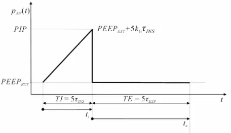
Figure 2 shows the advanced triangular waveform as
pAW excitation (AD_TRIANG). Unlike AD_SQUARE, where pAW is kept constant during the whole time of in-spiration (0 ≤ ti ≤ TI), in AD_TRIANG pAW increases linearly from minimum or PEEPEXT to maximum or peak (PIP) values assumed at the beginning (ti = 0) and at the end (ti = TI) of the time during inspiration (ti), respec-tively. The linear increase of pAW has been selected for smoothing RES discontinuity occurring at the beginning of every inspiration as response to upward pAW vertical transition of AD_SQUARE. As in AD_SQUARE, during the whole time of expiration (0 ≤ te ≤ TE) pAW is kept constant on PEEPEXT value.
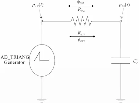
AD_TRIANG can be carried out by connecting the patient’s airways with an ideal generator creating a tri-angular waveform of pAW. The electrical-equivalent cir-cuit of AD_TRIANG generator connected to the patient's airways is shown in Figure3. The respiratory mechanics of patient (lung simulator) has been treated with a steady and linear physical model consisting of the respiratory airways resistance (RRES) connected in series to the lung compliance (CP) [9,45,46]. Such physical model does not include any inductance on account of negligible in-ertia of airflow as well as airways, lungs and chest tis-sues at very low breathing frequencies involved (10 - 12 act/min).
3.3.1. Inspiration Time
The application of the second Kirchhoff’s law to the circuit of Figure3 provides for the following equation:
0AWi i INS I NS i EAi i
p t R t p t (19)
AD_TRIANG (Figure 2) requires the following expres-sion of pAWi(ti):
Figure 2. The advanced triangular waveform as airways
Figure 3. Electrical-equivalent circuit of AD_TRIANG
gen-erator connected to the patient’s airways.
1AWi i EXT i i
p t PEEP k t (20)
where k1iis the slope of pAWi(ti) linear increase with time (ti).
As it is well known, INS(ti) is defined as the time derivation of vPi(ti), as follows:
d
d
Pi i INS i
i v t t
t
(21)
Considering (3) as well as by inserting both (20) and (21) into (19), the following equation results:
1
d
0 d
Pi i Pi i EXT i i INS
i P
v t v t
PEEP k t R
t C
(22)
In order to solve Eq.22, i.e. to find out the transient
and steady expressions of vPi(ti), it is useful to transform it from time (ti) to Laplace (s) variable domains, as fol-lows:
1
2 0 0
Pi i
EXT
INS Pi Pi
P
v s
k PEEP
R s v s v
s s C
(23) On account of both (1) and (9), the solution of (23) con-sists in the following expression:
2 1
2 1
i
INS INS
Pi
INS k FRC
FRCs s
R v s
s s
(24)
Eq.24 can be properly decomposed as follows:
2 1Pi
INS
A B C
v s
s s
s
(25)
The unknown constants A, B and C can be determined by setting Eq.24 equal to Eq.25, resulting as follows:
1i P
Ak C (26)
1
1P EXT i INS i P INS
BC PEEP k FRCk C (27)
1i P INS
Ck C (28)
Finally, by inserting (26), (27) and (28) into (25), the following expression results:
1 1 12 1
i P i P INS i P INS
Pi
INS
k C FRC k C k C
v s
s
s s
(29)
According to the Inverse Laplace Transform of (29), the function vPi(ti) assumes the following expression:
1 1 ei INS t
Pi i i P i INS
v t FRC k C t
(30)
The functions INS(ti) and pEAi(ti) can be determined considering (21) and (3), respectively, as follows:
1 1 ei INS t
INS ti k Ci P
(31)
1 1 ei INS t
EAi i EXT i i INS
p t PEEP k t
(32)
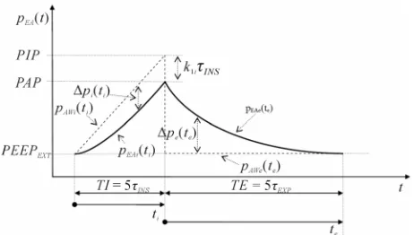
The functions vPi(ti), INS(ti) and pEAi(ti) are reported in Figure 4, Figure 5 and Figure 6, respectively.
The difference between pAWi(ti) and pEAi(ti) (pi(ti)) can be determined from both (20) and (32), as follows (Figure 6):
1 1 ei INS t
i i i INS
p t k
(33)
The same result of (33) could also be obtained by in-serting (31) into (19).
Considering (30), (31) and (32) at the beginning of inspiration time (ti= 0), the following expressions result:
0pi
v FRC (34)
0 0I NS
(35)
0
0EAi EXT AWi
p PEEP p (36)
(34) and (36) fit well (9) and (8), respectively (Figure 4 and Figure 6), according to the same steady conditions occurring in AD_SQUARE at the beginning of inspira-tion time (ti = 0) and thus at the end of last expiration time (te= TE).
[image:6.595.56.286.81.251.2] [image:6.595.306.541.84.443.2]Figure 4.Lung volume (vP(t)) as a function of time (t) resulting
[image:7.595.58.286.242.413.2]from the application of AD_TRIANG.
Figure 5. Respiratory airflow (RES(t)) as a function of time (t)
resulting from the application of AD_TRIANG.
Figure 6. Endoalveolar pressure (pEA(t)) as a function of time (t)
resulting from the application of AD_TRIANG.
steady condition, i.e. the end of transient inspiration time
(tTI= 5INS), (20), (30), (31), (32) and (33) provide for the following expressions:
5
5 1AWi INS EXT i INS
p TI PIPPEEP k (37)
5
1
1
5 5 1 e
4
pi INS i P INS INS
i P INS
v TI FRC k C
FRC k C
(38)
5
1 1
5 1 e
I NS TI INS k Ci P k Ci P
(39)
5
4 1EAi INS EXT i INS
p TI PAPPEEP k (40)
p TIi
5INS
PIPPAPk1i INS (41)(39) establishes that at the end of transient time (ti = TI = 5 INS), the increase of INS reaches a saturation value given by the product of CP with the linear slope (k1i) selected for pAW (Figure 5). This result is remarkable sinceINS(5INS) being independent on RINS, provides for a more physiological INS waveform adapting itself to
lung elastic characteristic (CP). Moreover, INS(5INS)
can be adequately adjusted by k1iregulation for a proper compensation of the actual CP value.
According to our purpose, (35) establishes the real smoothing of RES discontinuity occurring at the
begin-ning of every inspiration time (Figure 5). Unfortunately, unlike AD_SQUARE, according to (39), the final value of INS (INS(5INS)) is different from zero (Figure 5).
Such problem will be soon after removed with AD_ TRAPEZ (§ 3.4).
Both (33) and (41) establish that pi increases from
zero to a saturation value (Figure 6) given by the prod-uct k1iINSreached at the end of transient time (ti = TI =
5INS). Moreover, (32) establishes that during the
tran-sient time (0 ≤ ti ≤ TI) the second time derivation of
pEAi(ti) is positive, the time rate of pEAi(ti) increasing from 0 to k1i, that is the slope selected for pAWi(ti). The last results are equally remarkable if compared to those obtained with AD_SQUARE. Unlike AD_SQUARE, indeed, where pEAi(ti) waveform can be controlled only by selecting the maximum (PI) constant level of pAW (control of first order), in AD_TRIANG pEAi(ti) wave-form can be much safely controlled by selecting k1i value under of which the pEAi(ti) increasing rate with time is certainly kept (control of second order).
Considering both (34) and (38), VTID for an inspiration time equal to TI (VTID(TI)), results as follows:
5
0 4 1TID pi INS pi i P INS
V TI v TI v k C (42)
From both (12) and (42), VMIN for an inspiration time equal to TI (VMIN(TI)), results as follows:
48 1i INS MININS EXP
k
V TI
R R
(43)
(43) takes into account that TE is set equal to 5EXP (§
3.3.2).
Expressions (37)-(43) provide the rationale for the op-timization of ventilation control in AD_TRIANG during the time of inspiration.
k1i value required for delivering in the same time (TI =
[image:7.595.56.287.453.584.2]following expression:
1 4
EXT squ i
INS
PI PEEP
k
(44)
Under the last condition (k1i= ksqu1i), the following ex-pressions result:
4 EXT
PI PEEP
PIPPI (45)
PAPPI (46)
4 EXT PI PEEP
PIPPAP (47)
4 EXT INS
INS INS
PI PEEP PIP PAP
TI
R R
(48)
So, the peak of INS and PIP required in AD_TRIANG
for delivering in the same time (TI = 5INS) the same VTID and thus for reaching the same PAP as in AD_SQUARE shows a 75% reduction and increases a quarter of the difference between upper (PI) and lower
(PEEPEXT) pAWconstant levels, respectively.
The diagnostic procedure has to be implemented as follows. According to both (1) and (31), the measure-ment of the time required for reaching the end of tran-sient inspiration time (tTI = 5INS), i.e. for observing a
differential increase of INS with time lower than one
percent (1%) or saturated INS (INS(tTI=5INS)), is useful
for the determination of INS, as follows:
5 TI INS
t
(49)
According to (39), for a given k1ivalue, the monitoring of INS(tTI=5INS) leads to the determination of CP, as follows:
1
( 5 )
INS TI INS P
i t C
k
(50)
From (1), (49) and (50), RINS can be determined as fol-lows:
1
5 ( 5 )
INS TI i
INS
P INS TI INS
t k R
C t
(51)
Once INS, CP and RINS have been determined, TI should
be set equal to the measured tTI(TI = tTI) and k1i regula-tion should be performed in order to fit the clinical re-quirements on PIP, PAP, VTIDor VMIN through (37), (40), (42) or (43), respectively. In particular, concerning with dual-control mode, k1i values ensuring the pre-set VTID (k1iTID) or VMIN (k1iMIN) can be determined from (42) or (43), as follows:
1 4
TID iTID
P INS
V k
C
(52)
1 48
MIN INS EXP iMIN
INS
V R R
k
(53)
PIP values resulting from VTID (PIPTID) or VMIN (PIPMIN) dual-control mode, can be obtained by inserting (52) or (53) into (37), as follows:
5 4
TID
TID EXT
P V
PIP PEEP
C
(54)
5
48 MIN INS EXP
MIN EXT
V R R
PIP PEEP (55)
(54) and (55) show that PIPTID or PIPMIN are independ-ent on RRES or CP, respectively. That is extremely rele-vant from both physiopathological and clinical point of view since an increase of RRES (obstructive process) or a reduction of CP (restrictive process) does not affect the maximum pAW value reached for dual-control mode with pre-set VTID or VMIN, respectively.
The compensation procedure is required in order to assimilate ALVS with an ideal pAW generator providing for a real AD_TRIANG, i.e. triangular waveform as pAW excitation insensitive to patient’s respiratory characteris-tics and ventilator settings, through a proper triangular waveform of external resistance (REXT) of ALVS which controls pAW [9]. The electrical-equivalent network of ALVS is shown in Figure 7. According to ALVS con-figuration and performances [9], the compensation pro-cedure requires that during both inspiration and expira-tion the airflow crossing REXT, i.e. the external airflow (EXT), must be kept constant and equal to the equilib-rium value assumed in initial steady conditions during apnea (EXT0), for which the following expressions
[image:8.595.92.286.160.264.2]re-sult:
Figure 7. Electrical-equivalent network of ALVS. The
[image:8.595.311.536.505.674.2]0 RES
(56)
0 0 0 G EXT VEN G P R
(57)
0
0 0
0
G EXT EXT EXT EXT
G P R
PEEP R
R
(58)
VEN0 is the steady equilibrium value assumed by the
ventilation airflow (VEN), i.e. the airflow delivered by the generator. REXT0 is the lowest REXT value set for
PEEPEXT regulation by means of (58). PG and RG0 are the
output pressure and equilibrium value assumed by the internal resistance (RG) of ALVS generator, respectively, both set for VEN0 regulation by means of (57), according
to the following initial steady condition:
0 0
G EXT
R R (59)
Considering (58), (59) implies the following condition:
G EXT
P PEEP (60)
If EXT is stabilized on constant steady EXT0 value,
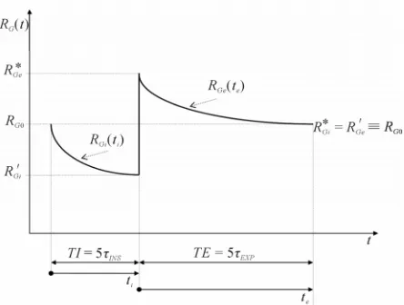
AD_TRIANG can be obtained by modeling REXT wave-form (REXT(t)) as linear increasing of REXT from REXT0 to
its maximum value ( *
EXT
R ) during inspiration (0 ≤ ti≤TI) and as instantaneous fall of REXT from REXT* to REXT0 followed by constant keeping of REXT on REXT0 during
expiration (0 ≤ te ≤ TE). From (57) and (58), REXT* is determined as follows:
* 0 0
0
G EXT
EXT
EXT G EXT
R PIP R PIP
PIP R
P PEEP
(61)
In particular, concerning with dual-control mode,
*
EXT
R values ensuring the pre-set VTID (
*TID EXT
R ) or VMIN ( *MIN
EXT
R ) can be obtained by inserting (54) or (55) into
(61), respectively, and considering (9), as follows:
* 0 5 1 4 TID TID EXT EXT V R R FRC
(62)
* 0 5 1 48MIN INS EXP MIN
EXT EXT
EXT
V R R
R R
PEEP
(63)
So, REXT(ti) to be implemented for dual-control mode during inspiration (0 ≤ ti ≤ TI) with pre-set VTID (REXT(ti)TID) or VMIN (REXT(ti)MIN), assumes the following expressions:
0 14
TID TID i
EXT i EXT
INS
V t
R t R
FRC
(64)
0 1 48
MIN INS EXP i MIN
EXT i EXT
INS
V R R t
R t R
R FRC
(65)
The stabilization of EXT during inspiration (EXTi(ti)) on
EXT0 can be carried out by proper modeling VEN wave- form during inspiration (VENi(ti)) according to the first
Kirchhoff’s low applied at airways node of ALVS’s net-work (Figure 7):
0
VENi ti EXTi ti INS ti EXT INS ti
(66)
By inserting both (57) and (31) into (66), the following expression results:
10 1 e i INS t G
VENi i i P
G P
t k C
R (67)
The second Kirchhoff’s low applied to the circuit of ALVS generator (Figure 7), assumes the following ex-pression:
0G Gi i VENi i AWi i
P R t t p t (68)
RGi(ti) is the RG waveform to be implemented for per-forming an effective compensation procedure during inspiration. By inserting both (67) and (20) into (68),
RGi(ti) can be determined as follows:
11 0
1 e i INS
G EXT i i
Gi i t
G
i P G
P PEEP k t
R t P k C R (69)
From (69), on account of (60), the maximum (RGi*) and minimum (RGi ) values assumed by RGi(ti) at the beginning (ti= 0) and at end (ti = TI) of the time during inspiration (ti), respectively, result as follows:
*
0
0
Gi Gi G
R R R (70)
1 0 Gi G Gi G i P G P PIPR R TI
P k C R (71)
So, considering that in coincidence with the end of in-spiration (ti= TI), i.e. the end of transient inspiration time,
RGiand REXTi assume their minimum (RGi ) and maximum ( *
EXT
R ) values, respectively, RGi modeling must take into account the following final steady condition:
*
Gi EXT
R R (72)
According to both (70) and (71), i.e. to condition
Gi R < RG0 and considering (61), (72) implies the following
condition:
G
P PIP (73)
Obviously, (72) and (73) replace (59) and (60), re-spectively. On account of both (73) and (58), (69) and (71) reduce to the following expressions, respectively:
1 0 0 1 0 1 e 1 e i INS i INS GGi i t
G i P G
G EXT
t
EXT i EXT P P R t P k C R R PEEP
PEEP k R C
01 0
1 0
Gi
G G EXT
Gi
G EXT i EXT P
i P G
P R PEEP
R R TI
P PEEP k R C
k C R
(75) Moreover, in order to avoid that RGi reaches unpractical reduced values, the following condition should be prop-erly taken into account:
0 2
Gi G R
R (76)
Considering (75), (76) leads to the following functional limitation on k1i value:
1
0 0
G EXT
i
P G P EXT
P PEEP
k
C R C R
(77)
The function RGi(ti) is reported in Figure 8. 3.3.2. Expiration time
The application of the second Kirchhoff’ law to the circuit of Figure 3 provides for the following equa-tion:
0AWe e EXP EXP e EAe e
p t R t p t (78)
As AD_SQUARE, AD_TRIANG requires the fol-lowing expression of pAWe(te):
AWe e EXT
p t PEEP (79)
As it is well known, EXP
te is defined as the time derivation of vPe(te), as follows:
d
d
Pe e EXP e
e v t t
t
(80)
[image:10.595.61.283.512.680.2]Considering (3) as well as by inserting both (79) and (80) into (78), the following equation results:
Figure 8. Internal resistance (RG(t)) of ALVS generator as a
function of time (t) to be implemented for performing the
compensation procedure in AD_TRIANG.
d
0 d
Pe e Pe e EXT EXP
e P
v t v t
PEEP R
t C
(81)
In order to solve Eq.81, i.e. to find out the transient
and steady expressions of vPe(te), it is useful to
trans-form it from time (te) to Laplace (s) variable domains,
as follows:
0 Pe
0EXT
EXP Pe Pe
P
v s
PEEP
R sv s v
s C (82)
From both (2) and (38), on account of continuity con-dition on vP when the switching between inspiration
and expiration takes place (vPe(0) ≡vPi (TI)), the
solu-tion of (82) consists in the following expression:
4 1
1
i P INS
EXP Pe
EXP
FRC
FRC k C s
v s
s s
(83)
Eq.83 can be properly decomposed as follows:
1Pe
EXP
A B
v s
s s
(84)
The unknown constants A and B can be determined by setting Eq.83 equal to Eq.84, resulting as follows:
A = FRC (85) B = 4k1iCPINS (86) Finally, by inserting (85) and (86) into (84), the fol-lowing expression results:
4 11
i P INS Pe
EXP k C FRC
v s
s s
(87)
According to the Inverse Laplace Transform of (87), the function vPe(te) assumes the following expression:
4 1 ee EXP t
Pe e i P INS
v t FRC k C
(88)
The functions EXP(te) and pEAe(te) can be determined considering (80) and (3), respectively, as follows:
4 1 ee EXP t i INS EXP e
EXP k t
R
(89)
4 1 ee EXP
t
EAe e EXT i INS
p t PEEP k
(90)
The functions vPe(te), EXP(te) and pEAe(te) are
re-ported in Figure 4, Figure 5 and Figure 6, respec-tively.
(Figure 6):
4 1e EXP t
e e i INS
p t k v
(91)
The same result of (91) could also be obtained by in-serting (89) into (78).
Considering (88), (89) and (90) at the beginning of expiration time (te = 0), the following expressions
result:
0 4 1
Pe i P INS Pi
v FRC k C v TI (92)
0 4 1i INS EXPEXP
k R
(93)
0 4 1
EAe EXT i INS EAi
p PEEP k p TI (94)
(92) and (94) fit well (38) and (40), respectively, ac-cording to continuity condition required between the end of inspiration and the beginning of expiration (Figure 4 and Figure 6). Unlike our purpose, (39) together with (93) establish a considerable discontinuity occurring on RES at the end of every inspiration when the switching between inspiration and expiration takes place (Figure 5). Such problem will be soon after removed with AD_ TRAPEZ (§ 3.4).
If TE is set equal to the time required for reaching the
steady condition, i.e. the end of transient expiration time
(tTE= 5EXP), (88), (89), (90) and (91) provide for the following expressions:
5
1
5 4 e 0
Pe INS i P INS Pi
v TE FRC k C FRCv (95)
5
4 1i INS
e 5 0EXP INS
EXP k TE
R
(96)
5 1
5 4 e
0
EAe INS EXT i INS
EXT EAi
p TE PEEP k
PEEP p
(97)
51
5 4 e 0
e INS i INS
p TE k
(98)
(95) and (97) fit well (34) and (36), respectively, ac-cording to continuity condition required at the transition between the end of every expiration and the beginning of the following inspiration (Figure 4 and Figure 6). More- over, according to our purpose, (96) together with (35) establish the real elimination of RES discontinuity occur-ring in coincidence with such a transition (Figure5).
The diagnostic procedure has been implemented as follows. According to both (2) and (89), the measure-ment of the time required for reaching the end of tran-sient expiration time (tTE = 5EXP), i.e. for observing a ninety nine per cent (99%) reduction of EXP with regard to its initial value (EXP(0)), is useful for the determina-tion of EXP, as follows:
5 TE EXP
t
(99)
According to (93), for a given k1i and INS values, the monitoring of EXP(0) leads to the determination of REXP, as follows:
1 4
0
i INS EXP
EXP k
R
(100)
From (2), (99) and (100), CP can be determined as fol-lows:
1 0 20
TE EXP EXP
P
EXP i INS
t C
R k
(101)
(101) can be employed for confirming the result ob-tained with (50). Once EXP, REXP and CP have been de-termined, TE should be set equal to the measured tTE (TE = tTE).
So, considering (58) and (79), REXT(te) to be imple-mented for dual-control mode during expiration (0 ≤ te≤
TE) with pre-set VTID(REXT(te)TID) or VMIN (REXT(te)MIN), assume the following expression:
TID
MIN 0EXT e EXT e EXT
R t R t R (102)
The compensation procedure, i.e. the stabilization of
EXT during expiration (EXTe(te)) onEXT0 can be carried
out by proper modeling VEN waveform during expiration (VENe(te)) according to the first Kirchhoff’s low applied at airways node of ALVS’s network (Figure 7):
0
VENe te EXTe te EXP te EXT EXP te
(103)
By inserting both (57) and (89) into (103), the following expression results:
10 4
e
e EXP
t
G i INS
VENe e
G EXP
P k
t
R R
(104)
The second Kirchhoff's low applied to the circuit of ALVS generator (Figure 7), assumes the following ex-pression:
0G Ge e VENe e AWe e
P R t t p t (105)
RGe(te) is the RG waveform to be implemented for per-forming an effective compensation procedure during expiration. By inserting both (104) and (79) into (105),
RGe(te) can be determined as follows:
1
0 4
e
e EXP
G EXT
Ge e t
G i INS
G EXP
P PEEP
R t
P k
R R
(106)
From (106), on account of (60), the maximum ( *
Ge
R ) and
[image:11.595.62.285.425.551.2]expiration (te), respectively, result as follows:
*
1
0 0
4
Ge
G Ge
G i INS
G EXP
P
R R
P k
R R
(107)
0Ge Ge G
R R TE R (108)
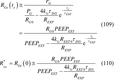
On account of both (58) and (60), (106) and (107) re-duce to the following expressions, respectively:
1
0
0
1 0
4 e
4
e
e EXP
e EXP G
Ge e t
G i INS
G EXP
G EXT
t i EXT INS EXT
EXP P
R t
P k
R R
R PEEP
k R PEEP
R
(109)
* 0
1 0
0
4
Ge
G EXT
Ge
i EXT INS EXT
EXP R PEEP
R R
k R PEEP
R
(110)
The function RGe(te) is reported in Figure 8.
So that, in conclusion, the implementation of (74) and (109) during the inspiration (0 ≤ ti≤TI) and expiration (0 ≤ te≤TE) times, respectively, ensures the compensa-tion procedure to be carried out, providing for an effec-tive AD_TRIANG.
From Figure2, Figure6, (12), (15), (16), (20), (32), (44), (79) and (90), it is easy to demonstrate that MAP
and MEP values of AD_TRIANG (MAPtri and MEPtri) result as follows:
EXT 0 625
INStri EXT
INS EXP
PI PEEP .
MAP PEEP
(111)
0 425 0 2
tri EXT
EXT INS EXP
INS EXP
MEP PEEP
PI PEEP . .
(112)
In comparison with (17), (111) shows a 37.5% reduction of the component of MAPtri above PEEPEXT with regard to the same component of MAPsqu. Moreover, in com-parison with (18), (112) shows a 31.3% reduction of the component of MEPtri above PEEPEXT with regard to the same component of MEPsqu, if the ratio between EXPand
INS is estimated twice.
[image:12.595.311.538.82.209.2]3.4. Advanced Trapezoidal Waveform as Airways Pressure Excitation (AD_TRAPEZ)
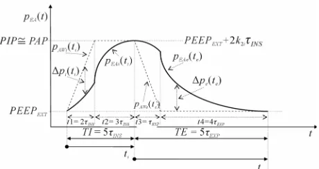
Figure 9 shows the advanced trapezoidal waveform as
pAW excitation (AD_TRAPEZ). In AD_TRAPEZ the time of inspiration (0 ≤ ti≤ TI) is divided into two sub
Figure 9. The advanced trapezoidal waveform as airways pre-
ssure (pAW(t)) excitation (AD_TRAPEZ).
sequent intervals of time lasting t1 and t2. During first (0
≤ti≤t1) and second (t1 ≤ti≤t1 + t2 = TI) intervals, pAW increases linearly with an higher slope (k2i) from mini-mum or PEEPEXT to maximum or peak (PIP) values and keeps constant on PIP value, respectively. Therefore, t1, t2 and k2i fit the following conditions:
1 2
t t TI (113)
2i 1i
k k (114)
As in AD_TRIANG, the linear increase of pAW has been selected for smoothing RES discontinuity occurring at the beginning of every inspiration, but its duration has been reduced (t1 < TI) for having a following interval (t2
= TI − t1) with constant pAW available for reducing to zero the final value of INS. Unlike AD_SQUARE and AD_TRIANG, during the time of expiration (0 ≤te≤TE)
pAW is no more kept constant on PEEPEXT. During the first interval of expiration (0 ≤te≤t3), pAW linearly falls with a slope k2e from PIP to PEEPEXT values for reduc-ing to zero the initial value of EXP, while during the second interval of expiration (t3 ≤te≤t3 + t4 = TE) pAW keeps constant on PEEPEXT value for reducing to zero the final value of EXP. Obviously, t3 and t4 fit the fol-lowing condition:
t3 + t4 = TE (115)
In such a way, according to our purpose, the discontinu-ity on RES occurring in AD_TRIANG at the end of every inspiration when the switching between inspiration and expiration takes place can be completely removed.
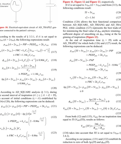
AD_TRAPEZ can be carried out by connecting the patient’s airways with an ideal generator creating a trapezoidal waveform of pAW. The electrical-equivalent circuit of AD_TRIANG generator connected to the pa-tient’s airways is shown in Figure 10.
3.4.1 Inspiration Time
[image:12.595.91.286.201.340.2]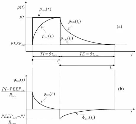
![Figure 7figuration and performances [9], the compensation pro-](https://thumb-us.123doks.com/thumbv2/123dok_us/9038251.400168/8.595.311.536.505.674/figure-figuration-and-performances-the-compensation-pro.webp)