REALIZATION OF MILKING ROBOT WITH TRACKING OBJECT FUNCTION
Department of Intelligence Robot, Busan University of Foreign Studies, BUFS
ARTICLE INFO ABSTRACT
In order to design the optimal well
system for automatic milking robot, which can reduce the stress of cows such as actuator noise sound and mecha
condition of a cow. Also, the robot manipulator must control tracking the teat cup to the detected nipple
designed and realized the automatic milking system that is t laser scanning unit and the manipulator has the
technology su
unit, manipulator protection bar, AC servo motor with feedback sensors, inverters and 3 axes position tracking boards using PIC18F8720 microprocessor and interface com
presented
simple, low cost and very quiet. The designed manipulator is realized by the servo posi
using the
control line. The designed robot specification for milking robot manipulator.
Copyright ©2016,Prof. Dr. Kyoo Jae Shin. This is an open access article distribute use, distribution and reproduction in any medium, provided the original work is properly cited.
INTRODUCTION
The industry of automatic milking system has developed by the need of the aging workforce reduction issues and strengthens the international competitiveness of farmers in t milking cow farms. The need of milking robots is required a productivity improvement and cost reduction through automation of the dairy animal husbandry.
although the domestic cow dairy farm business
decreasing in South Korea since year 1997, the robotic milking system is expanding in Korea because it becomes the large scale breeding operations in business scale basis.
milking robot have been developed in the early 1990s during the 3,000 level in the year 2010 more than 30 countries 90 farmers had used in Korea, about 120 farmers. The milk production working is the most important task of determining the farmers' income from livestock farms cows. Also, milking of cows is important for the other purpose of
prevention management and so farmers have to work hard every day to be repeated 2-3 times. The
cow comfort has a several works following by
*Corresponding author: Prof. Dr. Kyoo Jae Shin,
Department of Intelligence Robot, Busan University of Foreign Studies, BUFS, Busan, Republic of Korea
ISSN: 0975-833X
Article History:
Received 22nd August, 2016 Received in revised form 09th September, 2016 Accepted 18th October, 2016 Published online 30th November,2016
Citation: Prof. Dr. Kyoo Jae Shin, 2016. “Realization of milking robot with tracking object function
Journal of Current Research, 8, (11), 40997-41008.
Key words:
Milking Robot, Milking Manipulator, Embedded Control Unit, Laser Scanning, Moving Target Tracking, Fully electrical driving unit, Detecting nipples,
Manipulator Protection Bar.
RESEARCH ARTICLE
REALIZATION OF MILKING ROBOT WITH TRACKING OBJECT FUNCTION
ELECTRICAL DRIVING UNIT
*Prof. Dr. Kyoo Jae Shin
, Busan University of Foreign Studies, BUFS, Busan
ABSTRACT
In order to design the optimal well-being cow system, it had researched the fully electrical driving system for automatic milking robot, which can reduce the stress of cows such as actuator noise sound
mechanical vibration. The milking robot can detect exactly
condition of a cow. Also, the robot manipulator must control tracking the teat cup to the detected position. The proposed milking robot is designed by the fully
designed and realized the automatic milking system that is the nipples laser scanning unit and the manipulator has the tracking control to
technology such as 3 axes manipulator, detecting nipple unit, vacuum generating unit, milking storage unit, manipulator protection bar, AC servo motor with feedback sensors, inverters and 3 axes position tracking boards using PIC18F8720 microprocessor and interface com
presented nipple detection method and the electrical driving manipulator have the advantages of a simple, low cost and very quiet. The designed manipulator is realized by the
position control algorithm with tracking PID compensation. The presented robot is realized using the nipple detection unit, 4 teat cups, 3 axes robot arm, 6 servo motors and automatic milking control line. The designed robot is tested in the cow farm, which
specification for milking robot manipulator.
is an open access article distributed under the Creative Commons Attribution License, which in any medium, provided the original work is properly cited.
The industry of automatic milking system has developed by the need of the aging workforce reduction issues and strengthens the international competitiveness of farmers in the milking cow farms. The need of milking robots is required a productivity improvement and cost reduction through of the dairy animal husbandry. In addition, although the domestic cow dairy farm business has been year 1997, the robotic milking system is expanding in Korea because it becomes the large-scale breeding operations in business large-scale basis. Facilities for milking robot have been developed in the early 1990s during an 30 countries, about 90 farmers had used in Korea, about 120 farmers. The milk production working is the most important task of determining the farmers' income from livestock farms cows. Also, milking of cows is important for the other purpose of disease management and so farmers have to work hard
The Management of by; milking, feed
, Busan University of Foreign Studies, BUFS,
preparation, feeding, and care and cleaning of cow, milk transport, such as grazing and clean. In particular, the milking operation depends on the manual personnel. Because i requires the labor of 51.9% to
that, now a days automated important (Butler et al., 2012) ( order to reduce the labor for this
spread the automated milking robot by Prolion, Gascoigne Melotte, Lely, DeLaval VMS, Orion, Cemagref, AFRC, Duveldrorf, Reonardo, FAL (
et al., 2007). Because of the
decreases labor ratio and increases productivity, which
farmers have a big economic profit by the milking robot. Also, it has the advantages such as to
quality, and cow health effects. In addition, if it applies the robot to cow farms, the milking quantity increase three times a day, the milk yield is more producing 18% than manual case and it was increased by 25% in the producing cow of first time milk. From the results of the Image Do, if it increases the milking operation, it becomes
somatic cells contained in milk; hence the milk quality was improved and, also prevents the nipple damaging problem addition to measures temperature and conductivity during the milking can be found early mastitis of cows in dairy,
International Journal of Current Research
Vol. 8, Issue, 11, pp.40997-41008, November, 2016
Realization of milking robot with tracking object function using fully electrical driving unit
REALIZATION OF MILKING ROBOT WITH TRACKING OBJECT FUNCTION USING FULLY
Busan, Republic of Korea
had researched the fully electrical driving system for automatic milking robot, which can reduce the stress of cows such as actuator noise sound the nipples position in the moving condition of a cow. Also, the robot manipulator must control tracking the teat cup to the detected by the fully electrical driving system. It had nipples of the cow are detected by the to 3 axes driving unit. It includes high ch as 3 axes manipulator, detecting nipple unit, vacuum generating unit, milking storage unit, manipulator protection bar, AC servo motor with feedback sensors, inverters and 3 axes position tracking boards using PIC18F8720 microprocessor and interface communication using TCP/IP. The detection method and the electrical driving manipulator have the advantages of a simple, low cost and very quiet. The designed manipulator is realized by the fully electrical motor and PID compensation. The presented robot is realized by detection unit, 4 teat cups, 3 axes robot arm, 6 servo motors and automatic milking , which is satisfied with the design
ribution License, which permits unrestricted
preparation, feeding, and care and cleaning of cow, milk transport, such as grazing and clean. In particular, the milking on the manual personnel. Because it cows management working, so that, now a days automated milking robot system is very ) (Reine- Mann et al., 2001). In is milking, it had developed and automated milking robot by Prolion, Gascoigne DeLaval VMS, Orion, Cemagref, AFRC,
(Ion Boldea et al., 1999) (Shin ., 2007). Because of the automated milking robot, it
reases productivity, which gives to farmers have a big economic profit by the milking robot. Also, such as to Increase milk production, milk quality, and cow health effects. In addition, if it applies the ng quantity increase three times a day, the milk yield is more producing 18% than manual case and it was increased by 25% in the producing cow of first time the results of the Image Do, if it increases the s to be reducing the number of somatic cells contained in milk; hence the milk quality was improved and, also prevents the nipple damaging problem. In to measures temperature and conductivity during the milking can be found early mastitis of cows in dairy, the INTERNATIONAL JOURNAL OF CURRENT RESEARCH
several milking is effective to treat mastitis (Shin et al., 2007). In order to supply low cost milking robot in South Korea, we had analysed the milking robot technology about the teat detecting and drive control technology has shown in the Table 1, the robots has some problems to supply in South Korea, which are expensive and has A/S support issues. In this paper, it was considering the strengthening of market competitiveness, the designing of automatic milking robot and considering equipment of cow welfare for the economic improvement of farmers. It also had designed a tracking drive control system of milking robots and a detecting teat object using laser sensor. It has researched the object detecting methods using the vision, ultrasonic sensor and laser sensor in order to detect object. It needs the coordinated position data on automatic control, so that it had researched to detect the object position using position detecting boundary algorithms and image processing techniques. These algorithms are used to detect the moving object in fish robot, milking robot and self-driving vehicles and get the coordinated data with encircled by a rectangular object. This detection can be performed by using the edge detectors such as Roberts, Sobel and Prewitt. In the experimental results, analyse these detectors performance of the moving object (Shin et al., 2007) (Dote et al., 1990). In this paper, we applied two methods for detecting teat cups they are, one is boundary detecting algorithm and second one is laser sensor. It used the boundary image processing using camera, but it has some problem to apply in milking robot because of light reflection and color noise, etc. In this paper, we are proposed to detect teat position method of boundary detecting algorithm using the precision laser sensor. In general, the tracking control driving unit is realized by pneumatic unit, it has some problem of noise and vibration. It had affective the stress to cows, milk quantity decrease. It was verified by the performance test for the designed milking robot system.
Analysis of body condition for hostein cows
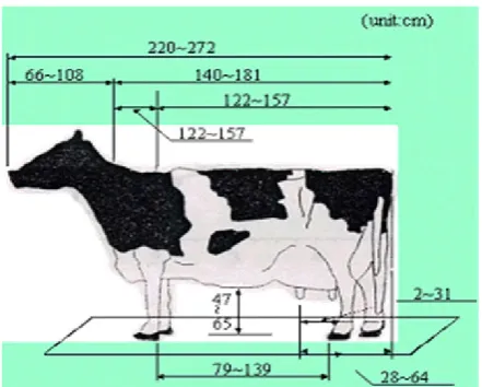
In order to design the milking robot system, now a days Holstein cow’s is spreading widely in South Korea. By measuring the positions of the two Holstein cows to 11 cows in the livestock Institute, which is located in South Korea, to realize this, it was designed the specifications of the standardization work of the stall and milking robot manipulators (Shin et al., 2007). The designed robotic milking cow, part of the body was measured as shown in Figure 1. The body full-length is 220 to 272 [cm], the distance between the front and back legs is 79 to139 [cm], the distance between from breasts to the floor is 31 [cm], the distance between the chest and the floor is 47 to 65[cm] respectively. The design specifications of the stall have been set by using the data of the measured cows and the information is applied to the design of the manipulator. In order to measure the relative position of the nipple rubbing, our beta Dean Solution of the red-brown nipple of the cow using the paper of A3 (420mm×279mm) size checks to mark the position of the nipple. Each cow milk production for each morning and evening was measured based on the relative difference in birth, and we are taking multiple times nipple measuring per a day we make report several days and then finally we make measurements as shown in the Figure 2. In addition, we have four flat nipples dimensions are marked. When we compare the Figure 1and Figure 2, along the x-Axis from front legs to rear legs, the distance is 79-139 [cm], from front nipple to rear nipple, the distance is 30-180 [mm] (Average distance is 130 [mm]). Along y-axis distance between the front nipple interval is 10-180 [mm] (Average
[image:2.595.323.544.182.359.2]distance is 65[mm]), distance between rear nipples interval is 130~260 [mm] (Average distance is 139[mm], diameter of the nipple is 16~33 [mm], length of the nipple is 100[mm] and nipple angle is90° to a position perpendicular to the back surface. In addition to the driving speed of the manipulator and the milking cup drive device, such as a milking cup shaft g axis and driving distance nipple location for attaching precisely the milking cups on the teats of the cow moves by distance and Table 2, by gender so Kung the nipple driving device set the mounting error and the milking cup.
Figure 1. Measured body size of Holsteincows
Figure 2. Measured nipples size of cows
Modeling of electrical driving control system
Modeling of brushless servo motor
The general robot is the noise and vibration generated by a pneumatic drive system and then cows are subjected to substantial stress by this environment. Because of this reason, it takes 2~4 weeks’ time to apply the robot to cows and this is environmentally not good. In order to realize the fully electrical driving control system, it needs the modeling of driving motor, which is the position and velocity feedback control using BLDCM (BrushLess DC Motor). The equivalent circuit model of three-phase BLDCM is applied to the milking
manipulator as shown in Figure 3. Where,
λ
abcd is the [image:2.595.323.546.395.558.2]magnet. The 3 phase stator voltage
v
abcsof brushless servo motor is converting to the dq-axis using the inverse conversion equation, which can be expressed in the equation (1) and (2), the phase voltage and phase current as shown in equation (3).abcs s qdos
K
v
v
(1)abcs s qdos
K
I
v
(2)
0
λ
ω
i
i
L
P
r
L
ω
L
ω
L
P
r
V
V
m r ds qs d s q r d r q s ds qs (3)In addition, the brushless dc servo motor of milking robot is represented by the counter electromotive force as three-phase permanent magnet synchronous motor. The torque induced in the motor by the current is as shown in equation (4), the mechanical motor torque is equal to the equation (5) (Shin, 2014).
m q d q qd
e λ i L L i i
2 P 2 3
T
(4) L r
r ω T
P 2 B dt d P 2 J
T
(5)Where,
r
s: Stator resistanced
q,
L
,
L
q d:
Axis inductance:
J
The rotor and load inertia:
B
Viscous friction coefficientm
λ
: Permanent magnet flux leakageP
: Number of Poled
q,
i
i
q,d:
Axis currentd
q,
V
,
V
q d:
Axis voltager
ω
: Rotor electrical angular speede
T
: Electrical field torqueL
T
: load torqueWhen the electric motor is driven by a vector control technique,
[image:3.595.308.520.54.396.2]which is assumed to contain the current controller, therein
i
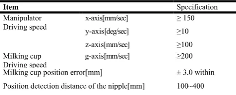
d on the d-axis current can be assumed to be zero torque, and the generated torque in the motor is shown in equation (6).Table 1. The designed specification of milking robot
Item Specification
Manipulator Driving speed
x-axis[mm/sec] ≥ 150
y-axis[deg/sec] ≥10
z-axis[mm/sec] ≥100 Milking cup
Driving speed
g-axis[mm/sec] ≥200
Milking cup position error[mm] ± 3.0 within
Position detection distance of the nipple[mm] 100~400
q l e
k
i
T
(6) [image:3.595.310.557.438.545.2]m l
λ
2
P
2
3
k
where,
(a) (b)Figure 3. Model of brushless servo motor (a) Reduced Model of 3 phase-2 pole, (b) Equivalent circuit of 3 phase-2 pole
Figure 4. The position tracking controller of milking manipulator
Design of teat-cup position tracking controller
Automated milking manipulator is controlled by the x, y, and z-axis independently of the drive shaft of Figure 3. In order to attach the cup to the cow nipple, positions tracking controller is designed as shown in Figure 4, which is to follow the laser nipple recognize the position command value. In addition, the actuator is driven the milking cups of manipulator to the cow's breast as shown in Figure 5. The object recognition unit can detect the position of the teats using the laser sensor; the detected position value is converted into a command position on the milking robot manipulator. Then it implements a position and speeds command value to control quickly and accurately mount the teat cup to a milking. The nipple recognition milking robot manipulator is transferred to three-axis by the independent driving unit and it can eliminate the mechanical vibrations using PID controller (B.SHAHIAN et al., 1993).The Nipple recognition apparatusis approximated
(s)
[image:3.595.34.277.676.774.2]results of observing the dynamic behavior of the cow, the bandwidth of controller was defined the reference bandwidth value to the below 2[Hz] and the dynamic bandwidth 10[Hz]
of
H
s(s)
to the approximation to the secondary order modelof equation (7), which is defined
s=0.5 andω
s= 62.8.2 s s s 2
2 s s
ω
s
ω
2ζ
s
ω
(s)
H
[image:4.595.317.543.54.201.2]
(7) [image:4.595.41.281.142.363.2]Figure 5. The proposed detecting position method using laser and ultrasonic sensor
[image:4.595.320.549.240.373.2]Figure 6. The laboratory model for detecting nipple
[image:4.595.47.278.403.556.2]Figure 7. The detecting object using laser sensor
[image:4.595.321.544.404.581.2]Figure 8. Nipple detection and teat-cups driving unit
Figure 9. Nipple detection and teat-cups driving unit
Figure 10. The designed teat-cup driving unit
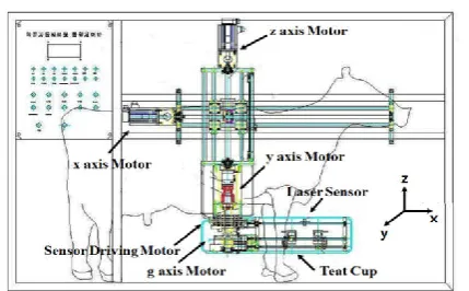
[image:4.595.46.278.586.759.2] [image:4.595.310.558.611.760.2]Figure 12. The designed manipulator of milking robot
Figure 13. Milking plane schematic of manipulator
Milking cup driving unit of Figure 6 consists of two servomotors, ball screws, LVDT and PID speed controller. The teat cup driver is controlled by the position command of nipple recognition device, which it takes place to vibration because of flexible body. The vibration problem can be eliminated by using the vibrations and torque ripple of the manipulator itself by equation (10). The frequency band including the integral gain has a 2ndorder low-pass filter is applied to the equation
(s)
H
i (8), which has frequency band 11.6 [Hz]. Also, it is applied the 2ndorder differential gain including the primary band pass filter to remove the manipulator vibration itself by equation (9), and it is possible to stable control in the dynamic band milking robot system, which has the band center frequency is 21.9[Hz]. This controller parameters is defined the speed controllerH
pid(s)
by the root locus method andfield test such as proportional gain
k
p = 0.35, applies theintegral gain
k
i =0.29, and differential gaink
d = 0.03 inequation (10). In addition to applying a damping coefficient
i= 0.80,
d= 0.48 and aω
i=72.8,ω
i=137.5 each of the filter functions to remove a mechanical vibration.2 i i i 2 2 i i LPF i i
ω
s
ω
2ζ
s
ω
K
(s)
H
k
(s)
H
(8) 2 d d d 2 2 d d BPF d dω
s
ω
2ζ
s
s
ω
k
(s)
H
k
(s)
H
(9)(s)
H
k
(s)
H
k
k
(s)
H
pid
p
i i
d d (10)Milking robot manipulator is composed of a phase current
controlled inverter
H
inv(s)
and the phase current feedbackgain
k
cur(s)
is applied to the speed control approximationmodel
1
(sL
R)
and gain feedback speedk
cur(s)
of the drive motor, as shown in Figure 9.In addition, the position ofthe load model
k
tsJ
being approximated position control isimplemented by the feedback gain
k
θ for each output; the position of the milking robot manipulator position with speed control is implemented. Therefore, when the teat position value detected by the teat scanning by the laser sensor of the teat recognition apparatus is applied to the position command ofthe manipulator, that the speed signal compensation
ω
cto the inverter is input to the PID speed controller of the formula (10) the speed of the drive motor It is controlled. The speed controller is the fast response and tracking the response of the manipulator is implemented according to the position and speed control on the drive shaft 3 axes.The proposed detecting method of nipple object
The review of image processing method
We designed the modeling of an object to detect the fish robot in the aquarium. The detection in the early stages of vision processing identifies the features in images that are relevant to estimating the structure and properties of objects in a scene. Edges are significant local changes in the image and are important features for analyzing images (William et al., 2012) (William et al., 1978). Edges typically occur on the boundary between two different regions in an image. Edge detecting is an image processing technique to finding the boundaries of an object within the images. It works by detecting discontinuities in brightness (Shin et al., 2016). Discontinuities in the image intensity can be either (a) step discontinuities, where the image intensity abruptly changes from one value on one side of the discontinuity to a different value on the opposite side, or (b) line discontinuities, where the image intensity abruptly changes value but then returns to the starting value within some short distance. However, step and line edges are rare in real images. Because of low-frequency components or the smoothing introduced by most sensing devices, sharp discontinuities rarely exist in real signals. Step edges become ramp edges and line edges become roof edges, where intensity changes are not instantaneous but occur over a finite distance. The edge set produced by an edge detector can be partitioned into two subsets: correct edges, which correspond to edges in the scene, and false edges, which do not correspond to edges in the scene. A third set of edges can be defined as those edges in the scene that should have been detected (Maria Petrou et al., 2005). This is the set of missing edges. The false edges are called false positives, and the missing edges are called false negatives.
[image:5.595.60.267.225.370.2]of edges. Edge detection uses local information to decide if a pixel is an edge, while edge following can use global information.
There are basic steps to create an edge detection operator.
(a) Filtering: Since gradient computation based on intensity values of only two points are susceptible to noise and other vagaries in discrete computations, filtering is commonly used to improve the performance of an edge detector with respect to the noise. However, there is a trade-off between edge strength and noise reduction. Filtering is necessary to reduce noise results in a loss of edge strength.
(b) Enhancement: In order to facilitate the detection of edges, it is essential to determine changes in intensity in the neighborhood of a point. Enhancement emphasizes pixels where there is a significant change in local intensity values and is usually performed by computing the gradient magnitude.
(c) Detection: We only want points with strong edge content. However, many points in an image have a nonzero value for the gradient, and not all of these points are edges for a particular application. Therefore, some method should be used to determine which points are edge points. In this, Sobel, Prewitt, Roberts and canny provides the criterion used for detection.
(d)Localization: The location of the edge can be estimated with sub pixel resolution if required for the application. The edge orientation can also be estimated (Gonzalez et al., 2010).
Types of Edge Detectors
(a) Gradient operators: It is older tool for detecting boundary. (b) Laplacian of Gaussian (Marr-Hildreth) detector: It can be useful in mathematical, electrical and electronics devices. (c) Gradient of Gaussian (canny) operator: It is more suitable for mechanical dynamics and robotics. In this method canny equation is used. The examples of gradient based an edge detector is Sobel, Prewitt, Roberts and Laplacian of Gaussian based an edge detector is Marr-Hildreth operator. Finally, the Gradient of Gaussian operator is canny edge detector. The Sobel operator is very similar to Prewitt operator. It is also a derivate mask and is used for edge detection. Like Prewitt operator Sobel operator is also used to detect two kinds of edges in an image: (a) Vertical direction (b) Horizontal direction (Steven et al., 2012; Space K et al., 1986; Tamal Bose et al., 2004; William et al., 2012).
The design of detecting object unit
It used the boundary image processing using camera, but it has some problem to apply in milking robot because of light reflection and color noise, etc. Laser sensor is one of the best sensor for detecting position than compare to stereo vision camera, it had researched using both laser sensor and stereo vision camera, but stereo vision camera has the same problem like light disturbance. So it is unable to recognition exact position of the cow nipple. Laser sensor can detect the exact position of the cow nipple at light or without light and it can be detected very accurate position using detecting object unit with teat cup. It is proposed detecting position method using Laser and ultrasonic sensor. The distance of applied laser sensor is 100~400 [mm] and accuracy is below 0.1%, which has a very
strong feature of the external environment. The sensing distance of auxiliary ultrasonic sensor is 1,000[mm] which is used the purpose of cow moving state. It had been a proven performance by the laboratory model for detecting teat as shown in Figure 3. The designed unit is applied for detecting teat in the farm field. When the cow-milking robot manipulators inside the entrance to the milking stall at the initial position, as shown in Figure 4, the manipulator rotates 90° to the y-axis direction. When the y-axis transfer device is arranged in a direction parallel to the breast, the nipple while feeding a laser sensor recognizes the device as a g-axis direction using senses the position of a cow teat. Next to the milking cup and aligned by the milking cup to the teat drive device, it is mounted to the milking cups by the z-axis drive motor on the nipple.
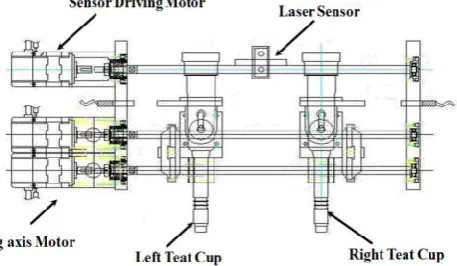
Nipple Detection and Teat-Cups Driving Unit
Nipple recognition unit is shown in Figure 5, 100~400 [mm] of the laser position detection sensor is capable of detecting the position and distance of each of the four nipples of the cow, and the sensor holder, and the ball screw shaft to provide a driving force, and a linear bush, the support unit, the servo motor and LVDT sensors. The teat unit is recognized by carrying out the scanning position the nipple angle and distance while feeding a g-axis direction in a state equipped with a laser sensor, the cow can detect the position and the nipple by object array. The teat detecting unit is a position command value is determined by scanning the nipple position. As it is shown in Figure 6, by the laser sensor and the sensor drive motor. Milking cups servo drive control device will each be equipped with two milking cups on the left and right mounting for milking the milking teat cup in both hands, as in a person. The milking cups are designed and manufactured drive unit configured as g-axis drive motor and milking the left and right in order to transfer the individual milking cup as shown in Figure 7. Laser sensor is Displacement measurement sensors, are laser sensors which measure precisely with a measuring range of cow nipple. Which is measure very accuracy, this sensor are particularly suitable for this project. Commonly measured characteristics include dimension and position.
Design of manipulator mechanism for fully electrical driving control
Design of teat cup driving unit
feeding device, as shown in Figure 4. In Figure 3, the lower the cow's breast, the y-axis transfer device is intended to enter the milking cups on the drive unit to the breast if the cows milking stall milking cups from the initial state ready to enter the milking stall stage. The y-axis transfer device is the y-axis drive motor, the planetary reduction gears, bearings, power transmission center axis, potentiometer rotatable for each detected power transmission clutch and the y-axis position meter and consists of a rotating belt for milking cups of the milking robot It determines the transfer direction of the y-axis.
Design of Manipulator Mechanism for Fully Electrical Driving Control
Z-axis transfer device is to drive in a vertical direction in order to mount the four milking cups to the teats. The transfer device consists of the z-axis drive motor, ball screw, shaft, linear bushings, support unit, the support and the z-axis position detecting LVDT sensor determines the transfer of the milking cup to the z-axis up and down direction.
Each step operates as follows.
Step 1: Initialize the aligning
Initialization step is aligning the position of the nipple state recognition device and the milking robot manipulator to position the initialization state and a state where the output value of each laser sensors, LVDT sensor on the display lamp and LCD.
Step 2:Detecting nipple
If the operating mode is the manual mode milking teat reader and 3-axis robot manipulators are respectively manual operations. Also, if the automatic mode is to detect the teat positions by scanning the teat position value using a laser sensor of the teat recognition.
Step 3: The milking cup mounting
This step is detected nipple position which the milking robot manipulator and which is converted into a command, is driving position of the milking robot arm to transfer a 3-axis mount the milking teat cup in alignment with each drive.
Step 4: The milking cup stripping
This step is the detachment of the milking teat-cup by free flow by using four sensors installed in the flow teat individually which is determined by the specific flow conditions while the milking teat cup attached.
Step 5: Milking robot arm to return
This step is used to return the milking robot arm, when the four milking cups milking left and right, then, milking robot manipulator is to be returned to the initialization position and exit the milking drive control the entire process.
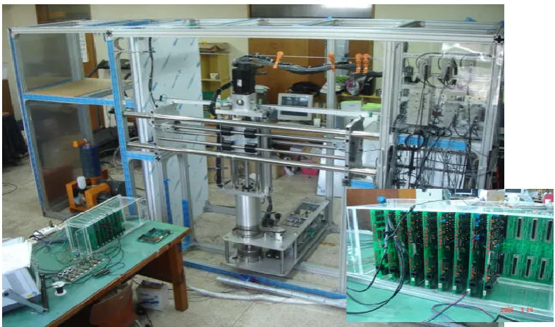
Design of hardware controller
The milking robot manipulator control box circuit as shown in the Figure 14, Figure 16and Figure 17and it has a microcomputer (PIC18F8720), for each independent axis, it has analog input signal conditioning circuit, 8-channel analog processor, analog-to-digital converters, digital-to-analog
converter, 12-bit parallel signal interface circuit EEPROM, and RS232C communication is configured by Ethernet. The control panel provides the ability to control the position precisely and speed of the milking robot manipulator being transported to the nipple reader and three axes. The production design milking robot manipulator control inverter and half embedded main controller as shown in Figure 10 and Figure 11. The main panel and the sub-control board, laser sensors, LVDT sensor interface with a high-frequency signal is shown in Figure 12. In addition to, an embedded control board is the main manipulator half DIO (Digital Input Output) 12-bit parallel signal processing microcomputer (PIC18F- 8720), It has applied using a digital converter and signal processing in parallel and the analog-digital converter.
[image:7.595.312.557.224.340.2](a) (b)
Figure 14. Embedded controller (a) Servo motor driver, (b) main and servo controller
Design of software controller
The milking robot manipulator control program is shown in Figure 15. In this flow chat Process of program explained step by step this program is shown in the Figure 18 and which is controlling the teat cup driving unit by laser sensor. Main steps involved in this process are sensor is scanning the cow nipple and collecting the position of the nipple at the same time, send nipple position to the teat cup driving unit. The teat cup driving unit start moving towards cow nipple and hold the cow nipple one by one or 4 cup at a time and hold the cow nipple and at a time vacuumed system start to suck the milk.
[image:7.595.311.558.529.667.2](a) (b)
Figure 15. The designed milking robot manipulator
EXPERIMENTAL RESULTS
Cow’s laboratory Model Experiments
Figure 16. Interface of control boards for milking robot manipulator
[image:8.595.111.505.537.769.2]Figure 18. The designed software for milking manipulator
This system detects the distance 100~400 [mm] and was applied to the dynamic bandwidth 100 [Hz] of the laser sensor. The Teats and milking cups recognition device, driving the manipulator device, which is implemented as shown in Figure13 and Figure 14.
[image:9.595.325.534.347.499.2](a) (b)
Figure 19. The experiment of nipple detection and teat-cups driving control
[image:9.595.39.289.416.537.2]This developed robot was performed Lab experiments with the model cow moveable. In addition to, it was recognized and milking the teat cup mount experiments using laser sensors, as shown in Figure 19.
Figure 20. Cows standing for experimental test
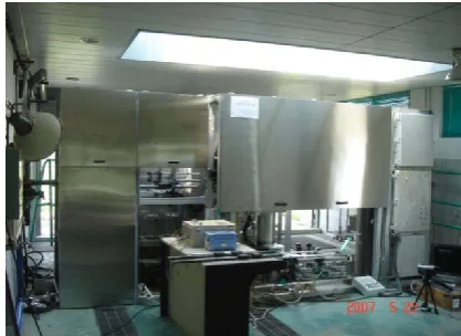
Figure 21. Overall experimental milking robot systems
Vacuum Generating system for Milk collecting
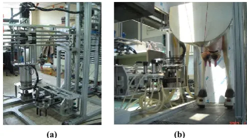
[image:9.595.308.549.611.786.2]This vacuum generating device whereby a vacuum is obtained by means of an ejector pump utilizing compressed air from a compressor provided vacuum pump. This system connected between the teat-cups and milk collecting equipment as shown in the Figure 22 and Figure 23.
[image:9.595.49.261.612.771.2]The vacuumed generator is mainly consists of compressor device, which is nothing but a compressor pump has implemented as shown in the Figure 18and the present invention relates to a vacuum generating device utilizing compressed air from a compressor provided to teat cups. It is possible to simply change its internal structure in response to use to suck the milk and send to milk collecting tank.
Figure 23. Automation milk storage equipment
Designed manipulator protection bar
Manipulator protection bar is protecting the manipulator from cow, sometime cow is very afraid to machine elements moving, and braking equipment mainly manipulator, so that we create this manipulator protection bar as shown in the Figure 24 and Figure 25. This manipulator is mainly consists of LVDT, distance sensor (ultrasonic sensor), screw bar for linear motion of bar this device is just controlling the cow
[image:10.595.308.551.209.769.2](a) (b)
Figure 24. Designed fixed cow bar for manipulator protection
(a) LVDT sensor with fixed bar driver (b) Ultrasonic sensor with fixed bar driver
Figure25.Designed fixed bar drive unit for cow
Figure 25. Designed fixed bar drive unit for cow
Experimental farm milking cows
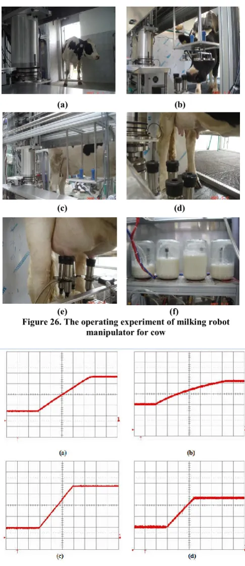
The robotic milking system is designed milking performance tests were conducted using cow pasture material Livestock Institute in Suwon, South Korea. This work was carried out to test the milking robot, as shown in Figure 26 to the cow, in order to verify the following ability of the manipulator is designed to experiment was performed according to the position command, the response time from the initial state position of the milking robot manipulator as shown in Figure 19.Milking cup drive shaft g axis and each axis x, y, a result of measuring the time response characteristics from the z-axis of the manipulator is as shown in Figure 12, g, x, z-axis output
(a) (b)
(c) (d)
(e) (f)
Figure 26. The operating experiment of milking robot manipulator for cow
Figure 27. Time responses of milking robot manipulator (a) x axis(0.5sec/div, 100mm/div)(b) y axis(0.5sec/div, 40deg/div)
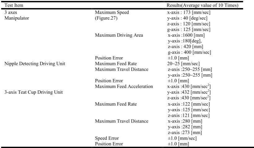
[image:10.595.42.287.443.553.2]Table 2. Experimental Results
Test Item Results(Average value of 10 Times)
3 axes Manipulator
Maximum Speed (Figure.27)
x-axis : 173 [mm/sec] y-axis : 40 [deg/sec] z-axis : 120 [mm/sec] g-axis : 125 [mm/sec] Maximum Driving Area x-axis :1600 [mm]
y-axis :180[deg], z-axis : 420 [mm] g-axis : 400 [mm/sec]
Position Error ±1.0 [mm]
Nipple Detecting Driving Unit Maximum Feed Rate 20~25 [mm/sec] Maximum Travel Distance z-axis :250~255 [mm]
y-axis :250~255 [mm]
Position Error ±1.0 [mm]
3-axis Teat Cup Driving Unit
Maximum Feed Acceleration x-axis :430 [mm/sec2] y-axis :432 [mm/sec2] z-axis :430 [mm/sec2] Maximum Feed Rate x-axis :122 [mm/sec] y-axis :125 [mm/sec] z-axis :121 [mm/sec] Maximum Travel Distance x-axis :280 [mm]
y-axis :282 [mm] z-axis :273 [mm]
Speed Error ±1.0 [mm/sec]
Position Error ±1.0 [mm]
signal was measured by an LVDT sensor is installed on each axis and y times axis potentiometer type was detected by the meter. In the experiments, we have measured which the result is x, y, z-axis and the axis of the milking cup drive shaft manipulator g axis recognizes a cow teat at the initial position
state. The tracking time
t
x= 2.3 [sec],t
y= 3.2 [sec] andt
g= 1.5[sec],
t
z= 1.2 milking cup [sec] it was attached to the nipple. In addition to, the maximum drive speed for each axis wasmeasured to
v
x= 150 [mm / sec],v
y= 40 [deg / sec],v
z= 253 [mm/ sec],
v
g= 42 [mm / sec].The attached time and the maximumdriving speed measurement results as shown in the Figure 27 and it was confirmed that satisfies all of the milking robot manipulator design specification of Table 2. When compared to the existing foreign milking robot performance, Lely, Delaval, Orion, Prolion products, uses the pneumatic cylinder actuators of the manipulator. In addition, the operation of the conventional robot manipulator in a manner that sequential milks the milking cup on the teat 1.
The proposed manipulator may be reduced by 40% compared with the time available mounting Figure 6 and mounted left and right at the same time milking cup as shown in Figure 7 on an existing milking robot. In addition, it is possible to reduce the proposed milking robot since all the driving devices are electric-driven adaptation training time a cow by way of pneumatic noise than existing robots within a week from the second-week old products. In particular, has the advantage to minimize the stress of milking cows. Milking robot may improve the milk quality by preventing a bacterial infection that can be infected at the time provided for the lack of labor and the milking farmer. Robot milking system accurately detects the position of the nipple and moving cows, the robot manipulator to track the detected position value must be fitted with milking teat cup. The proposed milking robot manipulator is scanning the teats using the laser position detection sensor and controlled by an independent three-axis drive mechanism via the embedded controller.
Conclusion
The most of all in milking systems have used the pneumatic actuator and assembly unit, which it affect the sound noise and mechanical vibration to cows. Because of the reasons, it take the milking system to apply for 20~30 days at least. In order to design the optimal well-being cow system, the robot had researched the fully electrical driving system for automatic milking work, which can reduce the stress of cows such as actuator noise sound and mechanical vibration. It had designed and realized the automatic milking system that is included high technology such as 3 axes manipulator, detecting nipple unit, vacuum generating unit, milking storage unit, manipulator protection bar, AC servo motor with feedback sensors, inverters and 3 axes position tracking boards using PIC18F8720 microprocessor and interface communication using TCP/IP. The designed manipulator is a laser sensor for detecting the teat position, four milking cups, a three-axis manipulator, an embedded control unit and the automatic milk control line. The proposed robotic system structure is simple, low cost, and by the robot, manipulator using the advantages of the electric drive motor with low noise. The robot was tested in Livestock Institute in Suwon, which is satisfied the performance requirements identified in the design of the milking robot milking through experiments, as shown in Table 2. It will apply to Korea milk cow farms in the near future, which will be compensate and improve the performance of disinfecting and processing of wash work using the total embedded drive control unit for the fully electrical automatic milking system.
REFERENCES
Butler, D., Holloway, L., and Bear, C. 2012. The impact of technological change in diary farming: Robotic milking systems and changing role of the stockperson" Journal of the royal agricultural society of England, Vol. 173, pp.1-6. Dote Y. and Kinoshita, S.1990.Brushless Servomotors
Fundamentals and application. Oxford.
Golnaraghi, F. and B. C.Kuo. 2010. Automatic Control Systems. Willey.
Kim,W. and D.W. Lee. 2005. Development of teat-cups attachment module for robot milking system. Journal of biosystems Eng., Vol.30, No.3, pp.179-184.
Kim, Y.U. 2003.Dairy.Rural development agency.
MariaPetrou and Costas Petrou, 2010. Image Processing - The fundamentals. Wily publication, 2nd edition, pp.591-625.
Maria Petrou., Panagiota Bosdogianni, 2005. Image Processing: The Fundamentals1st edition. Wiley, England, pp.125-138.
Milan Sonaka, Vaclav Hlavac and Roger Boyle, 2015. Image Processing, Analysis, and Machine Vision.4th edition, CENGAGE Learning, International edition, pp.116-160. Rafel C, Gonzalez and Richard E, Woods. 2010. Digital Image
Processing, 3rdedition, Pearson, pp.715-804.
Reinemann, D. J., Ruegg, P.L., and Davis, M. A. 2001. Assessment of robotic milking in Wisconsin- The 2001
ASAE Annual international meeting, paper No. 013008. Shahian, B. and Hassul, M. 1993. Control System Design
Using Matlab, Prentice Hall.
Shin, K. J. 2007. Development of milking robot system. Report of Ministry of Agriculture and Forestry, suncheon first college.
Shin,K. J. 2014. Design of Driving Control Unit and Milking Robot Manipulator. Journal of the Institute of Electronics and Information Engineers, pp.2124-2133, Vol.51, No.9. Shin,K. J. and S.I, Han. 2009. Robust Sliding Mode Friction
Control with Adaptive Friction Observer and Recurrent Fuzzy Neural Network. pp.125-130, International Journal of KIMICS, No.2.
Shin, K.J. and YogendraRao, Musunuri 2016. Realization of aquarium fish robot system with drawing fish of augmented reality. FCV 2016, Takayamagifu, Japan, pp.238-243. Shin, K.J. and YogendraRao, Musunuri. 2016. Design of
Aquarium Robot World Using Detecting fish robot Position Method”, The ICEIC Danang, Vietnam, pp. 81-84. Shin, K.J. and YogendraRao, Musunuri. 2016. Realization of
aquarium fish robot system with drawing fish of augmented reality. FCV 2016, Takayamagifu, Japan, pp.238-243. Shin, K.J. and YogendraRao, Musunuri. 2016. Realization of
Fish Robot Tracking Control Using Position Detecting Algorithm.ITC-CSCC 2016, Okinawa, Japan, pp.551-554. Shin, K.J.and YogendraRao, Musunuri.2016.Realization of
Fish Robot Tracking Control Using Position Detecting Algorithm. ITC-CSCC 2016, Okinawa, Japan, pp.551-554. Shin., K.J, and D.J, Kwon. 2007. Milking automatic robot and
milking automatic method. Patent no. 10-2007-0099351. Spacek, L.A. 1986. Edge detection and motion detection.
Image and Vision Computing, vol 4, pp. 43-53.
Steven C, Chapra, 2012. Applied numerical Methods with MATLAB for Engineers and Scientists. McGraw- Hill international edition, 3 rd edition, pp.497-531.
TamalBose.2004.Image Processing Fundamentals. John wiley & sons, USA, pp.570-581.
William J, Palm III.2012.Introduction to MATLAB for Engineers. McGraw- Hill international edition, 3rd edition, pp.263-293.
William K, Pratt.1978. Digital Image processing. John Wiley and Sons, England.