ISSN Online: 2333-9721 ISSN Print: 2333-9705
DOI: 10.4236/oalib.1104784 Sep. 29, 2018 1 Open Access Library Journal
Design and Construction of a Telescopic
Platform
Akinnuli Basil Olufemi
1, Olabaniji Taye Sola
2, Yakubu Anakobe Jimoh
31Department of Production and Industrial Engineering, Federal University of Technology, Akure, Nigeria 2Department of Mechanical Engineering, Landmark University, Omu-Aran, Nigeria
3Department of Computer Engineering, Federal Polytechnic Ile, Oluji, Nigeria
Abstract
A telescopic platform is equipment used in the Laboratory or Workshop to carry out different kinds of job on the ceiling e.g. fixing or replacing of elec-tric bulbs, fixing of elecelec-tric fans etc. it is also used to change streetlight on campus. Now that technology changes rapidly, the use of step ladders of dif-ferent kinds with low reliability and quite a number of limitations should gradually be replaced by less expensive alternative. To this end, Telescopic Platform has been designed and constructed to meet the urgent need for re-placement. Materials were locally sourced for such as Bevel gear, Sprockets, Chain, Power screw, Nut etc. and used for the fabrication, which involves welding grinding, fitting practices as well as assembly. The Telescopic Plat-form so produced is mobile, suitable for use on flat, sloping and terraced sur-faces with high reliability. Its height can be varied within a range designed. The telescopic platform designed can offer a good capacity of 834 N with effi-ciency of 85% and can conveniently carry an average human weight of 736 N.
Subject Areas
Industrial Engineering, Mechanical Engineering
Keywords
Telescopic, Platform, Stepladder, Design, Fabrication, Mechanical Elements
1. Introduction
The convectional platform or stepladder for internal use within building has a few imitations. It can only be used on plane surfaces. It becomes unstable on a slope or a terraced floor. Moreover, the stepladder is of fixed height. If such a How to cite this paper: Olufemi, A.B.,
Sola, O.T. and Jimoh, Y.A. (2018) Design and Construction of a Telescopic Platform. Open Access Library Journal, 5: e4784. https://doi.org/10.4236/oalib.1104784
Received: July 16, 2018 Accepted: September 26, 2018 Published: September 29, 2018
Copyright © 2018 by authors and Open Access Library Inc.
This work is licensed under the Creative Commons Attribution International License (CC BY 4.0).
DOI: 10.4236/oalib.1104784 2 Open Access Library Journal platform is to be built for changing the light bulbs in a workshop which is 6.5 metres high, it will be too big for easy movement and storage. As a result of these limitations, the telescopic platform is designed such that it can be used on a plane, a sloping as well as a terraced floor. Unlike the stepladder, the platform level is adjustable. The platform can therefore be set for use at various heights. At its lowest height it is handy for ease of storage and movement.
Other devices in the same category with telescopic platform include jack which is portable hand operated device for raising heavy weight through short distances, exerting great pressure, or holding assembled work firmly in position, as in jacking up a building to prevent settling or keep in position while replacing a foundation [1]. The jack’s effectiveness stems from the ratio of the load or weight of the object raised to the amount force applied to the handle of the jack. The ratio can be made quite high by the use of a gear or screw to regulate the upward extension of the jack. A ratchet allows a heavy weight to be raised in short successive stages, with jack locking whenever force is not being applied to its handled. Though limited in capacity by the requirement of portability and ease of manual operation, a jack may be viewed to lift, or exert a force of several tonnes [2].
Another example is a crane, which is a device that not only lifts heavy objects but also shifts them horizontally. Cranes are distinct from hoists, passenger ele-vators and other devices intended solely or primarily for vertical lifting and from conveyors, which continuously lift or carry bulk materials such as grain and coal. Cranes have come into their present widespread application only since the in-troduction of steam engines, internal combustion engines, and electric motors beginning in the nineteenth century [3]. The most prominent of that class known as Derrick cranes is the jib, or boom; this is a long beam that is structu-rally reinforced so that it will not bend. The jib is supported or held aloft by guy wires running from its top to its vertical mast or pillar that is itself stiffly braced; the guy wires set the angle at which the jib leans. The load may also be moved from side to side by having the jib pivot or rotate on its base around the pivot,
[4].
2. Literature Review
DOI: 10.4236/oalib.1104784 3 Open Access Library Journal or close in an endless track. They are usually designed to drag the train of a four-wheeled art around in loop to carry large products or materials for assem-bly on the conveyor system [5]. Slat conveyors consists of endless chains, driven by electric motors operating through reduction gears and sprockets, with at-tached spaced slats to carry objects that will damage a bolt because of sharp edges or heavy weight, Britannica [4].
Most modern elevators are propelled by electric motors with the aid of a counterweigh, through a system of cables and pulleys by opening a decisive role in a characteristic urban geography of many modern cities especially in United State, and promises to fill aim indispensable role in future city developments. The practice of lifting load by mechanical means during building operations goes to at least Roman architect-engineer Vitrullius in the 1st century BC de-scribed lifting platforms that use pulleys and capstans, or windlasses, operated by human, animal, or water power. Steam power was applied in such devices in England by 1800 [6]. In the early 19th centuries the hydraulic lift was intro-duced, in which a platform was attached to a plunger in a cylinder sunk in the ground below the shaft to a depth equal to the shaft’s height. Pressure was ap-plied to the fluid in a cylinder by a steam pump. Later a combination of pulley was used to multiply car’s motion and reduced the depth of the plunger. All these devices employed counterweight to balance the weight of the car, requiring only enough power to raise the load [7]. Prior to the mid-1850s, these principles were primarily applied to freight hoists. The poor reliability of the ropes used at that time made such lifting platform unsatisfactory for passenger’s case. When an American Elisha Graves Otis, introduced a safety device in 1853, he made the passenger elevator possible. Otis device, demonstrated at the Crystal Palace Ex-position in New York, incorporated a clamping arrangement that gripped the guide rails on which the car moved when tension was released from the hoist rope. The first passenger elevator was put into service in the Haugh Wout De-partment Store in New York City in 1857; driven by steam power, it climbed five stories in less than a minute and was pronounced success [8].
DOI: 10.4236/oalib.1104784 4 Open Access Library Journal more), increase both the fraction surface with pulley and safety factor, cable failure is rare [6]. The safety, usually mounted below car platform, is actuated by a speed governor through a rope. The rope pulls the safety to the on position in the event of excessive downward motion of the car. The device first cuts off ele-vator power; if excessive speed continues, it applies the safety break [10]. Eleva-tors lifted by hoisting ropes are required to have platform “safeties” devices de-signed to clamp unto the steel guide rails upon activation, quickly breaking the elevator to a halt. Now that the technology changes rapidly, the use of step lad-ders of different kinds with low reliability and quite a number of limitations should gradually be replaced by less expensive and more reliable alternatives.
3. Materials and Methods
3.1. Identification of the Required Components
The following components were required for the production of telescopic plat-form:
1) The screw pair 2) Bevel gear 3) Chain drives
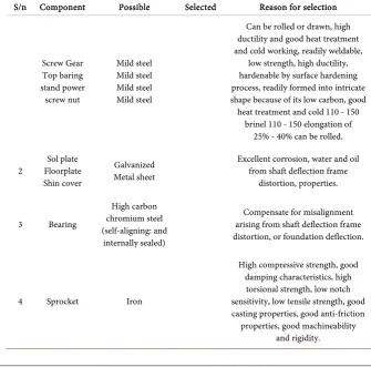
[image:4.595.201.537.408.739.2]The materials required for the production of the components of this telescopic platform are as shown in Table 1.
Table 1. Selected components and reason for selection.
S/n Component Possible Selected Reason for selection
Screw Gear Top baring stand power screw nut
Mild steel Mild steel Mild steel Mild steel
Can be rolled or drawn, high ductility and good heat treatment and cold working, readily weldable,
low strength, high ductility, hardenable by surface hardening process, readily formed into intricate shape because of its low carbon, good heat treatment and cold 110 - 150
brinel 110 - 150 elongation of 25% - 40% can be rolled.
2 Floorplate Sol plate Shin cover
Galvanized Metal sheet
Excellent corrosion, water and oil from shaft deflection frame
distortion, properties.
3 Bearing
High carbon chromium steel (self-aligning: and
internally sealed)
Compensate for misalignment arising from shaft deflection frame distortion, or foundation deflection.
4 Sprocket Iron
High compressive strength, good damping characteristics, high
torsional strength, low notch sensitivity, low tensile strength, good casting properties, good anti-friction properties, good machineability
DOI: 10.4236/oalib.1104784 5 Open Access Library Journal
3.2. Components Design Analysis
3.2.1. Design Analysis of the Screw Capacity of platform = 1000 N.
Maximum load on screw = 1500 N. Moment of inertia 4
π
64c d
I= (1)
The crippling load required
3 4 2
2 2
π π
4 256 c
Ed EI P
L L
= = (2)
The core diameter of screw is 28 mm.
Therefore designing for screw of 28 mm core diameter, selection was made from the table of basic dimensions for square threads in mm. (normal stress ac-cording to IS 4694-1968): Major diameter, (d0) =34 mm; pitch (p) = 6 mm and mean diameter, dm = 31 mm of screw were selected.
3.2.2. Design Analysis for Nut
P = 6 mm; do = 34.5 mm; D = 55 mm; H = 3.0 mm; L = 3p; (18 mm) θ = 5.70 μ = 0.1 = tanθ; α =10.47˚ Efficiency of screw (η)
(
)
tan tan
α η
α θ =
+ (3) 63.7%
η=
Design analysis for the force (P) and Torque (T) of the screws with mean di-ameter (dm) 31 mm. Horizontal force at the screw thread.
(
)
tan
P w= α θ+ (4)
870 N P=
Torque at the Screw
2m
r d
T P= =P×
(5) 13485 N mm
T = ⋅
3.2.3. Design for Stress
Compressive stress on the screw cross-section
c W A
σ = (6)
2 4.872 N mm c
σ =
where W is the designed load on the screw and A is the area of the screw shaft.
3.2.4. Torsion Stress (τ)
r T
J
τ = (7)
2 3.129 N mm
DOI: 10.4236/oalib.1104784 6 Open Access Library Journal Maximum Shear due to combined torsion and direct stresses (τm)
(
2 2)
1 21 4
2
m c
τ = σ + τ
(8)
2 3.965 N mm m
τ =
To check the screw thread for bearing, shear and bending stresses, bearing pressure on screw thread must be equal to that on the nut thread. Allowing a bearing pressure of 0.8 N/mm2 on the nut thread, shear stress on screw thread, (τs)
2π
s c W
r nh
τ = (9)
2 0.874 N mm s
τ =
3.2.5. Determination of Bending Stress
2 2
3 2.37
2π N mm
b WLrnh
σ = = (10)
3.2.6. Design Analysis of Gear Box
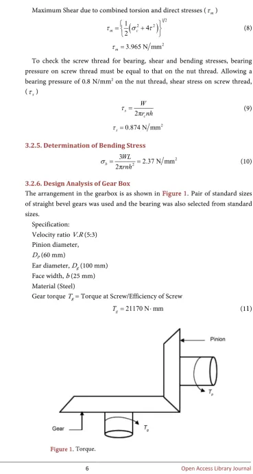
The arrangement in the gearbox is as shown in Figure 1. Pair of standard sizes of straight bevel gears was used and the bearing was also selected from standard sizes.
Specification:
Velocity ratio V.R (5:3) Pinion diameter,
DP (60 mm)
Ear diameter, Dg(100 mm) Face width, b (25 mm) Material (Steel)
Gear torque Tg = Torque at Screw/Efficiency of Screw 21170 N mm
g
[image:6.595.170.540.65.755.2]T = ⋅ (1
1
)DOI: 10.4236/oalib.1104784 7 Open Access Library Journal
Pinion torque P
P g
g D
T T
D
= × (12)
12700 N mm P
T = ⋅
3.2.7. Design Analysis for Chain
For the velocity ratio (V.R)
Pinion revolution per minute .
Manual turning per minute
V R= (13)
104.17
. 2.1
50
V R= =
Chain and sprockets selection (Holowenko, 1983) For driven Sprocket:
Nt2= 18; P = 14 mm
The Pitch dameter, 2
2 2N P2πt
D = (14)
2 80.2 mm
D =
For driver wheel:
Nt1 = 40; Pitch, P =14 mm
The Pitch dameter, 1
1 22πt
N P
D = (15)
1 178.25 mm
D =
The Velocity ratio, V.R
1 2
1 2
Output Speed, .
Input Speed, tt N n V R
n N
= = (16)
. 2.22
V R=
For the roller chain
Pitch, P = 14 mm; d = 5 mm; N = 5 mm Therefore chain length L
(
) (
1 2)
21 2
2 π R R
L C R R
C +
= + + + (17)
2808 mm L=
Torque required at pinion (Tp) taking efficiency to be 90% Torque at the driven sprocket,
1
2
P dn D
T T
D
= ⋅
(18)
31360 N mm P
T =
Torque required of handle with length 180 mm (L)
h Ldr
τ
τ =
(19)
175 N h
DOI: 10.4236/oalib.1104784 8 Open Access Library Journal 3.2.8. Design Analysis for Shaft and Base
The shaft is fully supported by the base of the platform so that it is not under much stress. The shaft was manufactured from solid drawn steel tubing to the following specification;
Inside diameter, D1 = 55.0 mm; Outside diameter, D2 = 65 mm; Length, L = 2400 mm.
The support legs of the platform were made from steel rods. Step ladder was attached to one of the legs to enable the operator climb unto the platform.
3.3. Determination of Stress on the Cross-Section of the
Support Legs
The support legs are attached to the shaft through flange ball bearings to allow for the rotation of the legs around the shaft. Weight of platform plus load on platform (W) (4000 N).
The direct load on the Cross-section of the support legs. Since there are four legs, therefore;
4cos WT F
θ=
4cosT
W F
θ
= (20)
(
)
1000 4cos 29.36 1147.4 N
F= =
Direct stress on the Cross-Section of the support legs
2 4 3.6 N mm2
π 5
F d
σ = = (21)
3.4. Design Analysis of the Jack
The jacks were manufactured to the following specifications; minor diameter dm (14.60 mm); normal diameter dn (19.10 mm); length, L (300 mm) and material selected was made from 0.25 C steel.
The pressure plate was made from Cast iron and the screw attached to it through a ball and socket joint to allow for self-alignment.
Compressive stress of the screw cross-section.
Total weight of platform plus load WT = 4000 N compressive stress on screw. Cross-Section
(
)
2 2 2
4 4000
π T 4 π 14.6 23.893 N mm
c c W d
σ = = × =
× (22)
This stress is sufficiently low compared to the Ultimate compressive stress of 430 N/mm2.
3.5. Machine Production
DOI: 10.4236/oalib.1104784 9 Open Access Library Journal bought from the market.
The major work done in the construction were cutting, filing and welding. There was very little machining. The construction process is as follows:
The nut was screwed into the power screw, which had already been attached to the gear box. The stopper was then machined to slide into the power screw and to just slide into the shaft. It was then welded to the end of the screw.
1) Sliding the stopper and screw down the shaft the nut was brought into po-sition at the upperpart of the shaft welded.
2) The platform was fixed on top of the gearbox and the gear made from steel rod fixed to the top of the platform.
3) The Chain drive was then assembled as specified in the design.
3.6. Production Cost
These costs include material cost, direct labour cost and overhead cost. All of these costs were incurred during the equipment fabrication stage.
3.7. Material Cost
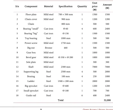
[image:9.595.163.534.388.748.2]The cost of raw materials purchased for the fabrication of the machine (Tables 2-4).
Table 2. Cost of materials.
S/n Component Material Specification Quantity price Unit (N)
Amount (N)
1 Floor plate Mild steel 700 × 500 mm 1 1500 1500 2 Chain cover Mild steel 900 mm 1 1200 1200
3 Chain 800 mm 1 500 500
4 Bearing “small” Cast iron Ѳ 60 4 600 2400 5 Bearing “big” Cast iron Ѳ 150 1 1500 1500
6 Top bearing Steel 1000 mm 1 500 500
7 Power screw Mild steel 1750 mm 1 1500 1500
8 Big nut Bronze 460 1 500 500
9 Gear box Mild steel 1 1000 1000
10 Bevel gear Mild steel Ѳ 350 × Ѳ 200 2 1000 1000
11 Sole plate Mild steel 1 300 300
12 Shaft Mild steel 2300 mm 1 7000 7000
13 Supporting leg Steel 2500 mm 4 500 2000
14 Brazing Steel 100 mm 4 250 1000
15 Ladder Steel 1500 × 200 mm 1 2000 2000
16 Big sprocket Cast iron Ѳ 400 1 1200 1200 17 Small sprocket Cast iron Ѳ 100 1 700 700
18 Guide rail Steel 6 400 2400
DOI: 10.4236/oalib.1104784 10 Open Access Library Journal
Table 3. Direct labour and fabrication cost.
S/n Component Description Quantity Unit price (N) Amount (N)
1 Guide rail 700 × 500 mm 1 1000 1000
2 Chain cover 900 mm 1 750 750
3 Ladder 800 mm 1 1000 1000
4 Supporting leg 2500 mm 4 750 3600
5 miscellaneous Assembly 3000 3000
Total 8750
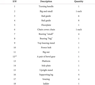
Table 4. Telescope stand.
S/N Description Quantity
1 Turning handle 1
2 Big and small 1 each
3 Rail guide 6
4 Rail guide 8
5 Floorplate 1
6 Chain cover; chain 1 each
7 Bearing “small” 4
8 Bearing “big” 1
9 Top bearing stand 1
10 Power bolt 1
11 Big nut 1
12a,b A pair of bevel gear 1
13 Platform 1
14 Sole plate 1
15 Upright stand 1
16 Supporting leg 4
17 brazing 4
18 ladder 1
Cost Summary
Material Cost = N32,200 Fabrication Cost = N8750 Overhead Cost = N10,000 Grand Total = N50,950
4. Results and Discussions
[image:10.595.208.539.258.552.2]DOI: 10.4236/oalib.1104784 11 Open Access Library Journal and also in the workshops. As concerned farm harvesting of fruits and trimming of palm front leaves, this can serve these purposes. The production cost of this telescope platform is N50,950 which is $141.53 US Dollar using the current ex-change rate of N360 per Dollar.
The efficiency of the machine can be calculated below:
Average capacity of machine adjustment factor
Efficency 100 85%
Average human weight ×
= × =
The telescopic platform has an average efficiency of 85% which can give a reasonable performance in use.
5. Discussions
The proposed Telescopic Platform has been successfully designed, fabricated and tested and found capable of lift and sustain a weight of 736 N. But getting to a load of 800 N, there was buckling developed by the supporting shaft as well as shear at some welding joints. The maximum load recommended on this plat-form is 750 N for safety assurance.
6. Conclusion
The design and construction of a telescopic platform had been carried out, and can meet the urgent need for the replacement of electric bulbs, and fixing of fans in the workshop. It can also be used for the erection of streetlights on campus; more so, it can meet the requirement of painting in high building as well as some activities as concerned harvesting of fruits, pruning of branches and removal of epiphytes.
Recommendation
Although this design satisfies the requirement of the purpose for which the plat-form is meant, considerable improvement can still be made in the following areas:
1) Operation: to save the operator the task of raising the platform manually, the platform can be redesigned such that the screw will be driven through the gars by an electric motor. This of course will increase the production cost.
2) Minimum platform level: it can be observed that the screw-pair principle employed in the design only serves to reduce the minimum platform level to about half the maximum level. This level is too high for compactness and storage when the platform is fully telescoped.
The minimum platform level can be reduced considerably by redesigning the platform using the strut and cylinder principles, in which the platform be raised or lowered by feeding hydraulic working fluid into hydraulic telescopic rams which will for the stalk of the platform. The working fluid can be fed to the rams by pumps which can be operated either manually or electrically.
DOI: 10.4236/oalib.1104784 12 Open Access Library Journal
Acknowledgements
Authors hereby acknowledge the Head of Department of Industrial and Produc-tion Engineering of Federal University of Technology Akure, Nigeria; for release of found and the workshop tools required for the production of this product. Also we can not but appreciate Engr. J. O. Fasan the Technician that carried out the fabrication of this platform.
Conflicts of Interest
The authors declare no conflicts of interest regarding the publication of this pa-per.
References
[1] Knowlton, H.B. (1950) Introduction to Hardening of Gears. SAE January Journal, 3, 33-42.
[2] Laughlin, H.H. (1961) Calculation of Force Condition of a Loaded Connection. Machine Design. McGraw-Hill Book Co., New York, 213-250.
[3] Roth Bart, H.A. (1964) Mechanical Design and System Handbook. McGraw-Hill Book Co, New York, 176-178.
[4] McGraw Hill Inc. (2003) Encyclopedia Britannica. McGraw Hill Inc., New York, 211-214.
[5] Lipson, C., Noll G.C. and Clock, L.S. (1950) Selection of a Power Suitable Type of Chain. Stress and Strength of Manufactured Parts. McGrawhill, Inc., New York. [6] Berezovsky, Yu., Chernilevsky, D. and Petrov, M. (1983) Simple Definition of
In-stalled Shafts and Hollow Ones. Machine Design. Mir. Publisher, Moscow, 355. [7] Faires, V.M. (1965) Design of Gearing for Exact Axis Distance. Design of Machine
Elements. The Macmillan Company, New York, 37-70.
[8] Kalpakjian, S. and Schmid, S. (2006) Manufacturing Engineering and Technology. Pearson Education Inc., Upper Saddle River, 1246-1250.
[9] Budynas, N. (2008) Shigley’s Mechanical Engineering Design. 8th Edition, McGraw-Hill Companies, New York, 15-351.
DOI: 10.4236/oalib.1104784 13 Open Access Library Journal
Nomenclature
σc = compressive stress (N/mm2)
ϵ = young’s modulus (N/mm2)
Ls = lead of the screws
P = pitch of the thread
I = moment of inertia
L = unsupported length
n = factor of safety
W = design load (N)
dc = core diameter
Do = outside diameter(mm)
do = major diameter of nut (mm)
H = depth of thread (mm)
η = Efficiency (%)
θ = Friction angle (˚C)
α = Helix angle π = constant
dm = Mean diameter
Ʈ = Torsion stress
Ʈs = Share stress
σb = bending stress
A = Area of the screw shaft (mm2)
T = torque