University of Twente
Fabrication of a full-ceramic
hydrophobic membrane for water
desalination
Chemical engineering Bachelor assignment
1
Summary
In this work a full-ceramic membrane, suitable for water desalination by means of Membrane Distillation (MD), was developed. A Si3N4 membrane was fabricated using the phase-inversion tape
casting method, which resulted in a thin skin layer with small pores at the top, finger-like micro channels that were almost back-through in the middle and a spongy layer at the bottom. The surface properties of the membrane were changed from hydrophilic to hydrophobic by pyrolysis of PDMS which introduced methyl groups on the surface. The obtained water contact angle was 117°. During sintering the membranes were immersed in a powder bed and pieces of powder stuck to the membrane, which were removed by sandpaper. This treatment damaged the skin layer and bigger pores were exposed, which caused the Liquid Entry Pressure to be lower than expected.
Other performance tests such as assessing the salt rejection and the gas and water vapour flux were conducted. The salt rejection was measured using a NaCl solution and a value of 99.8% was obtained, which is well comparable with literature values for various desalination membranes in MD.
2
Contents
Summary ... 1
1. Introduction ... 3
2. Theoretical background ... 5
2.1 Membrane distillation ... 5
2.2 Hydrophobicity ... 7
2.3 Membranes ... 8
2.4 Grafting ... 10
3. Scope of Research ... 12
4. Experimental ... 13
4.1 Fabrication ... 13
4.2 Grafting ... 13
4.3 Characterization ... 13
4.4 Performance ... 14
5. Results and Discussion ... 16
5.1 Characterization ... 16
5.2 Performance ... 20
6. Conclusion ... 23
7. Recommendations... 24
3
1.
Introduction
The population around the world is growing, and more and more people demand and strive for an improved quality of life. Despite their best intentions, this is always accompanied by an increase in consumption, which asks more and more of the earth’s resources. All around the world there are reports of resources in decline, from fossil fuels and rare earth metals to something as essential as water. For some of these resources there can be an alternative, for example, driven by increasing oil prices, renewable sources become interesting and solar power and wind energy have the potential to power the world’s economy for the decades to come. Rare earth metals however, or elements in general, do not have this option and careful recycling of products containing these elements is necessary to fight a threatening shortage.
A water shortage is different problem. Despite the fact that most of the Earth’s surface is covered by water, the availability of fresh water is not as obvious as it may once appeared, i.e. many thought it to be inexhaustible. Pressure from food production and population growth however are leading to declines. In many countries, there can be no replacement for declining water resources. Food scarcity and health epidemics, leading to societal decline, are likely outcomes as people chase diminishing water supplies [2].
In order to meet the overall demand and to avoid water scarcity, research focusses on techniques for water purification. There is a strong need to develop less energy intensive and environmentally friendly desalination techniques. First generation techniques were based on thermally driven processes like Multi-Stage Flash Distillation. But the evaporation of water takes a lot of energy and soon the attention shifted to membrane and pressure driven processes like Reverse Osmosis (RO) because of the lower energy input. RO is pressure driven; by overcoming the osmotic pressure of the solution, the solvent is pushed through a membrane, leaving the solute behind. When desalinizing sea water (~3.5 wt.% NaCl) the osmotic pressure is ~25 bars. Typically 2 – 3 kWh are necessary to desalinize one ton of water by RO [3]. At the moment RO accounts for 60% of all water desalination projects across the globe.
Although RO is energy efficient, high salinity brines cannot be treated due to the dramatically
increased osmotic pressure required. Besides, fouling tendencies has made the academic community search for other techniques. In terms of attention in research, RO is now being surpassed by third generation techniques like forward osmosis, capacitive deionization and Membrane Distillation (MD). Still, without heat recovery a minimum energy consumption of 628 kWh is necessary to create one ton of clean water using MD. However, MD uses low grade heat streams, making it easier to integrate in a wide variety of processes [1].
The process of MD is based on a thermal gradient across a microporous, hydrophobic membrane. Despite being a thermally driven process, the temperature of the hot feed is rarely higher than 90°C and usually between 50°C and 80°C. This gives the opportunity to use hot water coming from solar energy, geothermal energy and waste grade energy associated with low temperature industrial streams. Other advantages are a theoretical salt rejection of 100% (experimental results are
commonly ≥99%) and improved fouling resistance. The latter is often attributed to the fact that it is not solely a pressure driven process [4].
A high flux MD membrane should have low water vapour mass transfer resistance and besides a low thermal conductivity to prevent heat loss across the membrane. In addition, these membranes should have good thermal and chemical (e.g. acid and base) stability in order to handle the elevated operating temperatures and chemical cleaning [3].
4 liquid water containing possible solutes behind. As the liquid water will contaminate the permeate, it must not penetrate the membrane and thus the membrane is made water repellent (hydrophobic). Because the membrane needs to be hydrophobic, polymers that had intrinsic hydrophobic properties were the first materials to be used in fabrication of desalination membranes. Membranes made from polytetrafluoroethylene (PTFE), polypropylene (PP) and polyvinylidenedifluoride (PVDF) were already commercially available around twenty years ago [5]. But the requirements of good thermal and chemical stability do not apply to polymers and thus ceramic materials are chosen in this work. In 2004 it was Larbot et al. who first tried to use a ceramic membrane for water desalination. Ceramic membranes are not hydrophobic but instead hydrophilic due to hydroxyl groups on the surface, which causes immediate pore wetting [6]. The membranes were grafted using
Fluoroalkylsilane (FAS) to introduce hydrophobic functional groups on the membranes surface and make the material water repellent. FAS is an organic compound and therefore subject to the characteristics of organic compounds. It would be interesting to create a fully inorganic membrane, using an inorganic water repellent layer. PDMS was used to create hydrophobic surfaces on ceramic membranes [7-9]. The membranes are dip-coated in pure or dissolved PDMS and then placed in an oven under an oxygen free atmosphere.
Ceramic membranes used in MD are still largely limited to the four oxides, silica, zirconia, titania and alumina. Non-oxide materials such as silicon nitride (Si3N4) are often more chemically inert and it
would be interesting to create an inorganic membrane made from such a durable material. Si3N4 has
a low thermal expansion (~3 ∗ 10−6 𝐾−1) and has therefore an ability to withstand thermal shock. It has a high creep resistance and is relatively chemically inert, only dilute HF and hot H2SO4 react with
it [10]. With a melting point of 1900°C it is resistant to temperatures of most practical applications outside MD and anything within MD.
Low mass transfer resistance is essential for a high flux in MD and is achieved when straight micro channels are present in the membrane and connect the top to the bottom, the so called back through pores. Straight micro channels have another advantage: if the water vapour condenses within the pores there is a high chance of membrane wetting and permeate contamination. Straight micro channels lower the probability of early condensation. The phase inversion tape casting method is used to fabricate membranes that have straight micro channels.
5
2.
Theoretical background
2.1
Membrane distillation
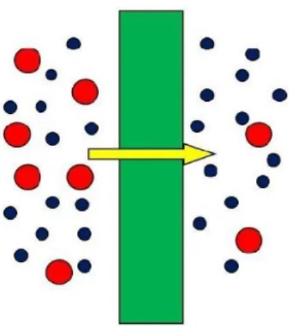
Water desalination is the process in which water is evaporated and water vapour is transported through a hydrophobic and microporous membrane. The driving force is the partial pressure difference between the feed and the permeate side [11]. Thanks to its hydrophobicity, the membrane cannot be wetted by the aqueous feed solution in direct contact with one side of this membrane; otherwise, immediate pore filling (wetting) will occur due to capillary forces. Liquid– vapour interfaces are thus created at each hydrophobic pore entrance allowing only the water vapour to transfer through the membrane [12]. Advantages of membrane distillation include the easy treatment of high salinity brines, relatively low temperatures and a theoretical selectivity of
100%.
In general, there are four different setups described [1, 5]. In Direct Contact Membrane Distillation (DCMD, Figure 1a) the cooling solution is in direct contact with the permeating side of the
membrane. This is the easiest and simplest configuration to realize practically, and useful for feeds with a fouling tendency because it is not pressure driven like Vacuum Membrane Distillation (VMD, Figure 1b). The flux obtained is however lower than in VMD and thermal polarization is high
compared to other configurations. Other disadvantages are that DCMD is relatively more sensitive to feed concentration and that the permeate quality is sensitive to membrane wetting.
In VMD the pressure is lowered on the distillate side. This setup is known for high obtained fluxes, the permeate quality is less dependent on membrane wetting and there is no possibility of wetting
6 from the distillate side. Also thermal polarization is very low. But the high pressure difference also has disadvantages. There is a high probability of pore wetting, high probability of fouling and the configuration requires an external vacuum pump and external condenser.
With Air Gap Membrane Distillation (AGMD, Figure 1c) a quiescent layer of air exists at the permeate side. This technique has the benefits of relatively high flux, low thermal losses, no wetting on
permeate side and less fouling tendency. However, the air gap provides an additional resistance to vapours, and the setup is more difficult to design. AGMD can also be difficult to model due to the involvement of too many variables.
In Sweep Gas Membrane Distillation (SGMD, Figure 1d) the distillate is taken away by an air stream. Thermal polarization is lower when this technique is used and there is no wetting from the permeate side. The permeate quality is independent of membrane wetting. However extra equipment must be added to establish the air flow which increases the complexity of the configuration. Pre-treatment of the sweep gas may also be necessary. Besides, heat recovery from the distillate is very difficult when using SGMD.
Ongoing research has developed new techniques that have improved energy efficiency or better permeation flux. The introduction of Material Gap Membrane Distillation (MGMD), Multi Effect Membrane Distillation (MEMD) and Permeate Gap Membrane Distillation (PGMD) show that there is still a lot of innovation possible, but also that specific process parameters ask for tailored solution. For completeness these configurations are named but a comparison falls outside the scope of this report.
One of the problems in MD, especially in DCMD, is thermal polarization. The result of thermal polarization is that the temperature on both sides of the membrane becomes equal and the water vapour flow stops. The temperature becomes equal because, in order to promote water molecules from the liquid phase to the gas phase, the enthalpy of vaporisation (𝛥𝐻𝑣𝑎𝑝= 40.65 𝑘𝐽 𝑚𝑜𝑙−1) has
to be provided. When the water starts to evaporate from the entrance of the pores, the total free energy decreases and the temperature subsequently drops. Water vapour travels through the pores and reached the permeate side. Here the water condenses and energy that was provided to
evaporate the water is now released; the temperature on the permeate side rises. The temperature difference induces the water vapour partial pressure difference, which is the driving force of the MD process. If no pressure difference exists the driving force is zero and no water vapour is transported through the pores.
In order to keep the temperature difference level, a fast flowrate and turbulent flow at the feed side can help to keep the temperature level at that side. Fast removal of distillate at the permeate side is also helpful. However, this problem can never fully be averted.
Another problem that also happens at the interface is the occurrence of supersaturated solutions and is the result of concentration polarization. By removing water in a fast pace, the concentration of salt rises locally. This affects the viscosity, the boiling temperature and the water vapour pressure. The latter is derived from Raoult’s Law:
𝑝𝑖 = 𝑝𝑖∗𝑥𝑖 (1)
In which 𝑝𝑖 is the partial vapour pressure of component 𝑖 in the gas phase. 𝑝𝑖∗ is the vapour pressure
of the pure component and 𝑥𝑖 is the mole fraction of that component. As the concentration of salt
rises, 𝑥𝐻2𝑂 becomes smaller and the vapour pressure decreases, leading to a lower flux. When the
7 crystals can also nullify the hydrophobic nature of the membrane, which can lead to membrane wetting and contamination of the distillate.
A solution can be a turbulent flow on the feed side but elevated local salt concentrations will always be a problem in MD. If the module has run for a certain period of time and the flux is decreased dramatically, the membrane can be taken out, cleaned (ultrasonically) and dried. After such a treatment the performance usually fully recovers [13].
2.2
Hydrophobicity
If a surface contains non-polar groups such as methyl (−𝐶𝐻3) or ethyl (−𝐶𝐻2− 𝐶𝐻3) groups, polar
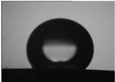
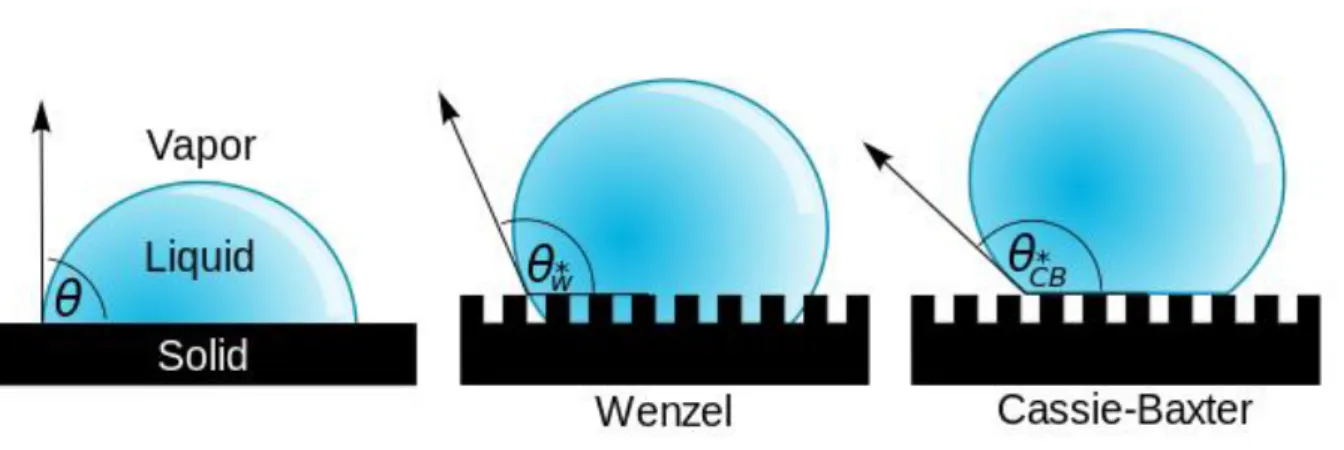
water molecules which are in contact with that surface become more organized, forming clathrate-like structures and make the surface area in contact with the material as small as possible. Droplets will not spread out but will form a spherical-like structure. The angle between the sphere and the material is called the contact angle and is a measure for the hydrophobicity. From an angle of 90° on, the material is categorized as hydrophobic. In the theoretical case of a perfect sphere the angle between the water and the material is 180°.
The hydrophobicity of materials is not only determined by the functional groups on the surface, but also the surface morphology plays a role. Rough surfaces can achieve much higher contact angles as Figure 2 shows. If a material has a contact angle larger than 150°, the material can be called
superhydrophobic. This superhydrophobicity is also dependant on the roll-off angle, which is a dynamic measurement, instead of the static contact angle. If a water droplet rolls of a surface under an angle less than 10° and the former criterion is also met, the material is deemed superhydrophobic [14].
Figure 2: A droplet resting on a solid surface and surrounded by a gas forms a characteristic contact angle 𝜃. If the solid surface is rough, and the liquid is in intimate contact with the solid asperities, the droplet is in the Wenzel state. If the liquid rests on the tops of the asperities, it is in the Cassie–Baxter state.
8
2.3
Membranes
A membrane can be described as a barrier that lets for instance substance A pass through, but retains substance B; it is selective. Membranes are more than filters that separate on pore size, some separate on affinity of a certain compound. Membranes come in all shapes and sizes, made from polymers, metals or ceramics. Roughly dividing in two categories results in dense and porous membranes, in which transport in dense ceramic materials happens by the movement of ions in lattices. Porous membranes are the subject of this report and contain micro channels of various sizes to allow mass transfer. (For water desalination by MD the pore size is between 0.1 – 1 µm). The shape of these micro channels can be straight or wrinkled, the latter resulting in a higher tortuosity. The phase-inversion method produces ceramic membranes that have finger-like pores, which are straight micro channels with a low tortuosity and therefore a low mass transfer resistance.
Preparation of porous ceramics usually involves pyrolyzable pore formers such as graphite. These compounds are burned out during sintering of ceramic green bodies, leaving pores in the final ceramics. Porous ceramic material can also be prepared by the freeze-casting method, where the solvent is solidified and removed by sublimative drying [15].
Phase-inversion tape casting is another way to prepare porous ceramics. To prepare planar ceramic membranes, ceramic powders are dispersed in a polymer solution, tape casted and then immersed in a water bath to begin the coagulation reaction.
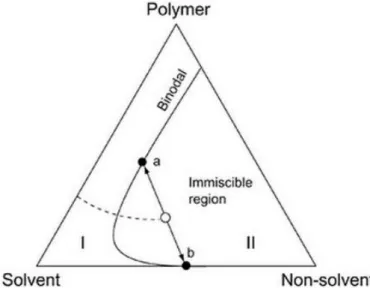
Experimental results of the phase-inversion method are abundantly available. A reaction of a polymer solution after immersion in a non-solvent results in a series of micro channels that are numerous and small at the interface and merge together to form a few larger ones. The bottom of the green tape, however thin, is almost never reached and a spongy layer is formed. The precise mechanism of both the origin and growth of the finger-like pores is still subject to debate. As Wang et al. observed, a substantial amount of research has been done in the field of polymer membranes [16]. Smolders et al. [17] eventually formulated a theory that nucleated droplets of the polymer-lean phase (point ‘b’ in Figure 4) in the suspension just below the interface were the starting point of these pores. Existing theories, summarized in the paper of Smolders et al., were disproven. One theory stated that mechanical stresses caused ruptures on the interface, which would then function as convection cells for non-solvent flows. Another theory stated that matrix shrinkage causes the finger-like pores. Despite the fact that this still may happen in certain polymer-solvent-non-solvent systems, there is no evidence that this is the driving force responsible for the formation of the micro channels.
The growth of nucleated droplets further down into the green tape was something Smolders et al. explained by the fact that droplets could not grow towards the interface due to a lack of solvent. The droplets also could not go sideways because of other droplets. This last statement is also an
explanation for the observed periodicity of the micro channels. Micro channels would grow and then collide and merge to give lower surface tension, and the growth eventually slows down due to diffusional limitations and result in a spongy bottom layer [17].
9 Figure 4: Ternary diagram in which the demixing of a polymer solution upon the introduction of a non-solvent is displayed.
The solution moves from region I to region II and demixes into a polymer-rich (a) and a polymer-lean (b) phase.
As Lee et al. correctly described, much literature is available on different effects of fabrication parameters, but an improved understanding of the formation mechanism is still necessary to control the membrane characteristics and enhance the reproducibility [18]. Fang et al. described the viscous fingering phenomenon, which occurs when two immiscible mediums with different viscosities are brought in contact with each other. This process can also be a suitable explanation for the obtained morphology [15].
The viscous fingering phenomena is well known and both experimental and mathematical
descriptions are available. Saffman and Taylor first published in 1958 a mathematical description on the phenomenon in a so called Hele-Shaw cell [19]. The models reported since then fall outside the scope of this work.
There are two types of viscous fingering. The first one occurs when the solvent and non-solvent are immiscible; a distinct interface is present and interfacial tension plays an important role. The second type occurs when the two liquids are miscible. In this case there is no interfacial tension but the dispersion of the finger fonts affects the fingering process.
In a system with a non-solvent that is displacing a ceramic suspension there is always a distinct interface, but still the suspension and the non-solvent are miscible to a limited extent. This results in a system with varying interfacial tensions and varying viscosities.
One of the parameters that influence the formation of these materials, is the ratio between polymer and solvent. In ceramic suspensions the polymer acts as a binder for the ceramic particles that creates a matrix. During sintering the polymer is burnt out and the ceramic particles form the structure of the membranes. For hollow fibre Si3N4 membranes the most advantageous
10 Figure 5: Bending strength, porosity and average pore size of the Si3N4
hollow fibre membranes as a function of the ceramic powders/PESf ratio [13]
Figure 6: Bending strength and porosity of Si3N4 membranes sintered at different temperatures. (Figure obtained after personal communication with Wang Junwei)
2.4
Grafting
In order to make the surface of the membrane water repellent, non-polar molecules are introduced to the surface. In order to make a lasting coating, the non-polar molecules need to be chemically bonded to the material and not physically adsorbed on the surface. Ceramic membranes have hydroxyl groups (−𝑂𝐻) on the surface which makes the surface hydrophilic. To chemically bond a compound to the surface, it needs to react with these hydroxyl groups.
Silicon based polymers have the ability to link with hydroxyl groups, are categorized as inorganic and have been proven to make surfaces hydrophobic. These polymers come in a wide variety of
configurations, the backbone often contains elements such as oxygen (called polysiloxanes), nitrogen (polysilazanes), carbon (polycarbosilanes) and boron (polyborosilanes) or mixtures of them. The silicon in the backbone is bonded to two organic side groups, which can be alkyl groups, such as methyl or ethyl, allylic groups in which a methylene bridge is attached to a vinyl group, or aryl groups of which benzene is the simplest.
Polydimethylsiloxane (PDMS, Figure 7) is an organosiloxane that is known to produce hydrophobic surfaces. The polymer backbone of alternating silicon and oxygen atom can be cleaved and silanol compounds (𝑆𝑖 − 𝑂𝐻) can be formed. (Figure 8) This reaction is carried out in aqueous alkaline solutions. For alumina surfaces, PDMS has been introduced to the surface and was able to react with the hydroxyl groups, as FT-IR showed. The result were polymer chains of siloxane that changed the hydrophilic properties of the surface [8]. (Figure 9)
Figure 7: Polydimethylsiloxane Figure 8: Reaction of PDMS with aryl (-Ar) compounds and alkyl (-R) compounds [8]
11 temperature paths have been found by Thermal Gravimetric Analysis (TGA). Between 50°C and 300°C shaping takes place. At these temperatures the macrostructure of the material can be altered. At the same time crosslinking between polymer chains can occur, typically between 100°C and 400°C. Beyond 400°C pyrolysis begins. This is the start of the so called polymer-to-ceramic conversion. Although pyrolysis is still happening for certain compounds at 1400°C, crystallization comes in to play at around 1000°C. For PDMS it is observed that at about 1000°C amorphous SixCyOz is obtained. This
is not preferable because the organic side groups will be completely removed at that point.[7]
12
3.
Scope of the project
Research in ceramic membranes for water desalination in a MD setup have gained attention over the last few years. Oxide materials coated with organic compounds for hydrophobic effects have
debatable performance in terms of durability. A fully ceramic material with hydrophobic properties for MD has not been reported but would be promising in terms of chemical and thermal stability. A tough material, even for ceramic compounds, is Si3N4, which is the basis for the membranes
fabricated in this work. Although hollow fibre Si3N4 membranes have been reported, planar samples
have promising features but are not described in literature. The membranes in this report are fabricated using the phase-inversion tape casting method to create finger-like pores which are back-through to obtain low mass transfer resistance. Scanning Electron Microscopy (SEM) is used to verify if the expected pores are formed and if characteristic grains are present.
To change the surface properties of ceramic materials used in MD, mainly fluoro-alkyl silanes (FAS) are reported as interesting candidates to hydrophobize oxide ceramic surfaces. In this work a fully inorganic material is developed by dip-coating and pyrolysis of PDMS. The combination of this technique with the Si3N4 material is new. SEM will again be used to determine if there have been any
changes in morphology after coating. Static contact angle measurements will verify if the surface has been changed to hydrophobic and FT-IR will be used to give an indication of the bonds formed on the surface.
13
4.
Experimental
4.1
Fabrication
A polymer solution was formed by dissolving 2.24 g of the dispersant O-(2-aminopropyl)-O’-(2-methoxyethyl)-polypropylene glycol (AMPG) and 8.00 g of the polymer polyethersulfone (PESf) in 40.00 g N-methyl-2-pyrrolidone (NMP) by milling for 2 h. To this solution 56 g of starting ceramic powders (93 wt.% α-Si3N4 + 2 wt.% Al2O3 + 5 wt.% Y2O3) were added to the solution, followed by
milling for 48 h at room temperature using a ceramic container and milling balls in a planetary mill. The additives (2 wt.% Al2O3 + 5 wt.% Y2O3) were used as sintering additives to promote sintering and
grain growth of the rod-like Si3N4 grains [13]. The slurry was degassed for 10 minutes using a vacuum
pump and casted on a Mylar sheet with a doctor blade with a gap height of 0.8 mm. A doctor blade was pulled over the sheet at a speed of 20 cm/min. The casted slurry was immediately immersed in water at room temperature and left for 24 hours for coagulation [20].
After drying under ambient conditions, the green tape was cut into round pieces and placed inside a powder bed composed of 30 wt.% BN + 70 wt.% starting powders, followed by sintering [21]. The powder bed is necessary to protect the membranes form the graphite of the furnace that will
otherwise contaminate the membranes and influence their mechanical strength. During the sintering the green tape was heated to 1200°C in 2 h, then heated to 1700°C for 1h 40m and then kept at 1700°C for 4 h in a graphite furnace under N2 atmosphere. The N2 atmosphere is necessary because
exposure to the O2 in air would convert the Si3N4 to silica.
After the sintering procedure the membranes were taken out of the oven and treated with sand paper shortly to remove large particles from the powder bed stuck to the surface. The membranes were then treated ultrasonically in ethanol three times for 15 minutes each. After each ultrasonic treatment the membranes were dried at 80°C.
4.2
Grafting
The membrane surface was modified by coating. Via a dip-coating procedure, the membranes were once gradually immersed into pure polydimethylsiloxane (PDMS) with an average lifting dip-coating speed of 0.2 mm/s.
In a tubular oven with a constant argon flow, the coated membranes were dried at 220oC for 2 h,
then heated to 400oC to induce polymerisation. 400°C was held for 30m and the sample was further
heated to 650°C. At this temperature it was calcined for 3 hours. The applied heating/cooling temperature profiles in all steps were set at a relative slow rate of 3-5 K/min [9].
This procedure was carried out twice. In between the procedures the membrane was cleaned ultrasonically and dried at 80°C.
4.3
Characterization
Scanning Electron Microscopy (SEM)
SEM produces images of a sample by scanning it with a focused beam of electrons. The electrons interact with atoms in the sample, producing various signals that can be detected and that contain information about the sample's surface topography.
Static contact angle
14
FTIR
Fourier Transform Infrared spectroscopy uses radiation in the infrared spectrum to bombard a sample with energy. A large range of wavelengths is used and at each wavelength molecules can absorb the energy of the radiation if that specific wavelength corresponds with bending and stretching vibrations within the molecule. Specific compounds have specific wavelengths for absorption of infrared energy and if a graph is made of the absorbance of the sample at each wavelength, the presence of certain functional groups can be determined.
In this report a grafted and a non-grafted sample will be compared with FTIR. Peaks present in the grafted sample but not in the non-grafted sample will be analysed according to their specific wavelength [22].
4.4
Performance
Liquid Entry Pressure (LEP)
The LEP of a grafted membrane gives the pressure at which water penetrates the membrane. By filling the side of the module that is normally connected with the nitrogen feed with deionized water and slowly increasing the pressure, the point at which water penetrates the membrane was
determined.
Gas permeability
The gas permeability of grafted and ungrafted membranes was determined using pure nitrogen at different pressures. The membranes were sealed with a sealing liquid (Silicone adhesive sealant, Zhizhen No-703) between two metal cylinders that were connected on one side to the nitrogen feed and on the other side to a soap film flow meter. The permeability was measured in the pressure range 0.1 – 1.0 bar at 0.1 pressure intervals. For each pressure, the permeability was measured three times.
Because of the sealing liquid, the surface area that was exposed to the nitrogen feed was therefore smaller than the surface area of the entire membrane and had also an irregular shape. To estimate the real surface area, the membranes’ diameter was measured five times and the average was used to calculate the area, as if it was a perfect circle.
The flux was calculated using: 𝐽 =𝑡∗𝐴𝑉 in which V is the volume in litres, t the time in hours, A the surface area in m2 and J the flux in L m-2 h-1.
Water desalination
In order to test the desalination performance of the grafted Si3N4 membranes, nine membrane were
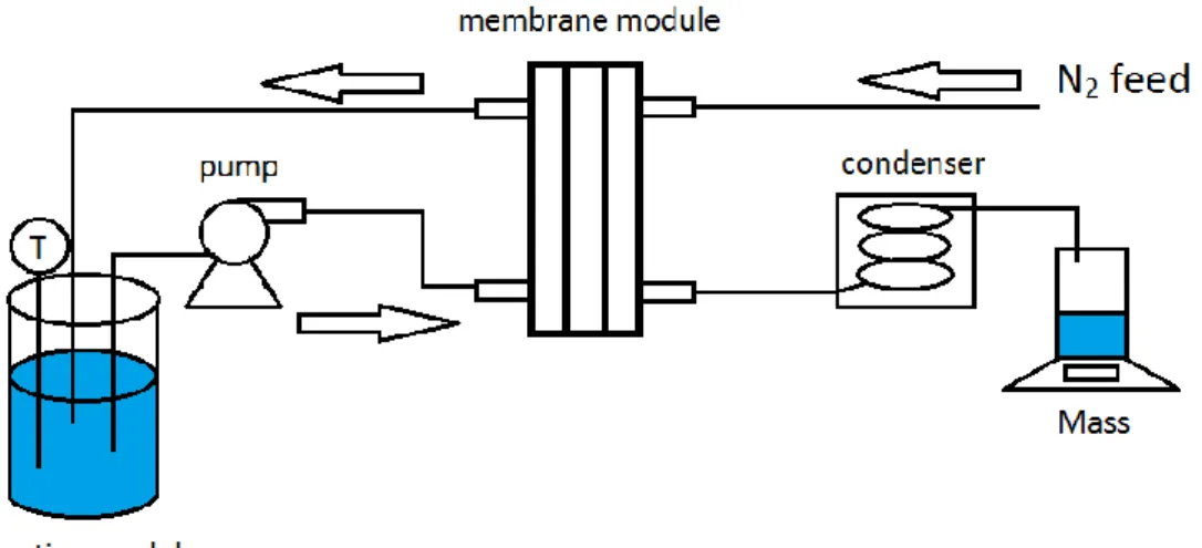
sealed in a module with a sealing liquid (Silicone adhesive sealant, Zhizhen No-703) and exposed to a hot salt water feed. To calculate the real surface area of the membranes, again the membranes’ diameter was measured five times and the average was used to calculate the area. The salt water feed consisted of a water bath of 12,00 L of deionized water and 480,0 gr of dissolved NaCl (3.85 wt.%). As Sweep Gas Membrane Distillation was used, a sweep consisting of a constant flow of nitrogen (pressure 1.2 bar) was applied at the cold side of the membrane. The nitrogen was chilled by a condenser and the permeated water collected in a glass beaker that was weighed every 35 minutes.
After six weighing measurements were done, the water flow of 20 mL s-1 was stopped for 30 minutes
15 Figure 10: Schematic representation of the SGMD setup used
16
5.
Results and Discussion
5.1
Characterization
FTIR
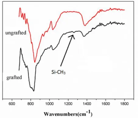
Figure 11: An IR spectrum of both a grafted sample (lower graph) and an ungrafted sample (upper graph)
From the FTIR spectrum (Figure 11) some differences between grafted and non-grafted membranes are visible. The most important changes are that the high intensity peak at ~840 cm-1 has become
much broader after grafting, indicating a second peak at ~800 cm-1. There seems to be a peak at
around ~755 cm-1. Also has the dip in the upper graph close to a 1000 cm-1 become less deep in the
bottom graph and there is a small but noticeable peak at around 1250 cm-1 for the grafted sample
(indicated by the arrow in Figure 11). The sharp peak at 840 cm-1 is characteristic for Si 3N4.
The peak at 800 cm-1 can be explained in two ways. 𝑆𝑖 − 𝐶𝐻
3 bonds in polydimethylsiloxane
configuration gives of a peak at 800 cm-1, which would indicate the presence of siloxane polymer
chains on the surface. However, it is also known that 𝑆𝑖𝐶 gives of a strong peak at the same
wavelength. This would mean that the temperature applied during the grafting procedure would be too high, converting most of the polymer chains to amorphous ceramics.
The peak at 755 cm-1 is also probably from 𝑆𝑖 − 𝐶𝐻
3.
The change at 1000 cm-1 can be attributed to a number of bonds, most probable is the 𝑆𝑖 − 𝑂 − 𝑆𝑖
backbone of the structure. The peak at ~1250 cm-1 is pointed out because it is usually associated with
𝑆𝑖 − 𝐶𝐻3 bonds in a polysiloxane structure, in which the silicon atom has three methyl groups bonded to it. When the silicon atom has two methyl groups attached to it and is part of the backbone, the peak shifts to 1260 cm-1. With this resolution it is not clear which compound is
depicted. In the end it does not matter, because whether the silicon has two or three methyl groups attached to it, hydrophobic groups are present on the surface [22].
Because of the intensity of the peak at 800 cm-1 is large, and 𝑆𝑖𝐶 is known to give of strong peaks,
17 properties of the membrane, the grafting procedure should be carried out at lower temperatures to prevent converting the polymer chains to amorphous 𝑆𝑖𝐶.
SEM images
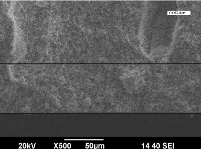
Figure 12: A cross-sectional image of a Si3N4 membrane Figure 13: A cross-sectional image of the sponge layer
Figure 14: SEM image of the top of a Si3N4 membrane Figure 15: SEM image of the bottom of a Si3N4 membrane
Figure 12 shows a cross-sectional image of a silicon nitride membrane. It shows that the phase-inversion tape casting worked, finger-like pores are formed and they are numerous near the skin (top) layer, but merge and become larger when growing downwards. The membrane is about 0.36 mm thick. Figure 13 shows the spongy (bottom) layer, a rather thin layer but it would block the vapour flux when this membrane is used in membrane distillation. To the naked eye the skin and spongy layer were indistinguishable.
18 it is reported that bigger pores also work for membrane distillation and can even enhance the flux, pore wetting is also more probable. On Figure 15 the advancement of the growing finger-like pores is also visible. In this sample the spongy layer completely removed and instead of the numerous smaller pores, few pores with pore size of ±40 µm are formed.
Figure 16: SEM image of an ungrafted Si3N4 membrane. The characteristic
needle-like shape grains are visible
Figure 17: SEM image of a grafted Si3N4 membrane. The change in
morphology, the tiny white dots, are clearly present
Figure 18: SEM image of an ungrafted Si3N4 membrane. Between the
needle-like grains, bits are present
Figure 19: SEM close-up of a grafted Si3N4 membrane
Figure 16 is an image of an ungrafted Si3N4 membrane at higher magnifications. The characteristic
needle-like grains are present, which is an indication that the material is Si3N4. There are however
also oddly shaped bits present with sizes of several µm, which have likely stuck to the grains during sintering and cannot be removed by ultrasonic cleaning. However, the presence is not bad, the bits might enhance the mechanical stability of the membrane.
Figure 17 shows a grafted membrane, and because it has the same magnification as the ungrafted sample next to it, a comparison about the morphology can be made. On the grafted membranes clearly nanoparticles are visible, covering the surface of the uppermost grains.
19 nanoparticles cover a large part of the grains and their sizes range from 20 nm to 50 nm. However, it is also visible in the upper right corner, that this grain is not covered at all. This means that during the dip-coating procedure the PDMS liquid could not penetrate/cover inside the structure of the
membrane.
Contact angle
Membrane Side Place Angle (°)
1 1 1 120
2 120
2 1 104
2 118
2 1 1 113
2 120
2 1 117
2 118
3 1 1 106
2 1 122
2 132
4 1 1 124
2 118
2 1 118
2 110
Average contact angle 117,3
Table 1: Contact angles of a random selection of the membranes used in the Membrane Distillation setup
On each membrane the contact angle was measured four times, twice on each side. The results are given in Table 1. The droplet was always placed near the edge of the membrane, in order to get a clear picture. On side 1 of membrane 3, only one clear picture could be taken due to the wrinkled shape of the membrane. To compare the grafted samples with not grafted samples, strictly speaking there should have been contact angle measurements of not grafted samples as well. However, on a non-grafted sample the water droplet would fall straight through. From these results it is clear that hydrophobicity has changed after grafting
From the FTIR, the SEM images and the contact angle test it is clear that a hydrophobic material is created and that a chemical bonding is present between grafting agent and membrane. The average contact angle is not very high but more information about the properties of pyrolysis products of PDMS may give insight in the correct temperature for the grafting procedure. Moreover, if the polymer chains on the surface provide the hydrophobic behaviour and converting them to SiCO (silicon oxycarbide) means hydrophobicity is lost or reduced, thermal stability is strongly reduced.
20
5.2
Performance
The membranes in this work had often a wrinkled or dome-like shape. The wrinkled shape of the samples was a feature that made it difficult not only to do the contact angle tests, but handling of the material in general was sometimes complicated. Removing the spongy layer completely was impossible as the sandpaper would only scratch a small portion of the surface. Some membranes were so deformed that they did not fit in the desalination or gas permeability test modules. The origin of this wrinkled shape is not known. Perhaps by removing the green tape from the circular knife, for cutting the desired discs, a dome shape is introduced that is later sintered into the material. This dome shape would be caused by the fact that the membranes are always stuck to the knife, and that removal is done by pressing out the membrane disc by hand or by hitting the circular knife from the other side to create pressure causing the membrane to ‘pop’ out. As the membrane is stuck to the sides, the middle of the flexible green tape bends before the membrane is removed. After sintering and treatment with sandpaper it was often seen that the edges were getting rough and the middle was not, or the other way around. Also imperfections in the green tape can be responsible for deformations during the sintering procedure. Solid particles could be responsible, but air bubbles could also be an option.
Liquid Entry Pressure
The LEP of two membranes was measured. The
membrane depicted with the blue line in Figure 21 was also used in the gas permeability test. The membrane depicted with the red line came from the same green tape as membranes that were used for the water desalination test.
The LEP is quite low, a possible reason is that during the treatment with sand paper, the skin layer is
damaged which causes the pores exposed to be bigger. This is also confirmed by the SEM pictures, pores were bigger than desired values.
The low LEP means that this membrane is not suitable for processes in which the pressure becomes a factor (such as VMD). Table 2 shows LEP values for other membranes of the same material or same
macrostructure. Values for commercial membranes are provided by Drioli et al.
Type of membrane Material Coating LEP (bar) Reference
Hollow fibre Si3N4 FAS 3.4 [21]
Hollow fibre Si3N4 FAS 3.25 [13]
Planar Alumina FAS 2 [20]
planar Si3N4 SiOC 1 This work
Table 2: Comparison of LEPs available in literature
21
Gas Permeability test
In order to evaluate the results of the gas permeability test, data from literature is included. Because different papers use different axes, for comparison the gas permeability graph is from this report is every time the graph on the right. Figure 23 is based on results from is from Ren et al. [20] on FAS-grafted planar alumina membranes while Figure 25 represents results from Zhang et al. [13] on hollow fibre, FAS-grafted Si3N4 membranes.
Figure 22: Gas permeability test from this work, axes configured to Figure 23 Figure 23: Gas permeability test with alumina membranes coated with FAS. Samples were tested by Ren et al. [20]
Figure 24: Gas permeability test from this work, axes configured to Figure 25 Figure 25: Gas permeability test with Si¬3N4 hollow fibre membranes coated with FAS. Samples were tested by Zhang et al. [13]
The membranes that were sealed in the module for this test originated from the same green tape. Their properties are therefore comparable. From the gas permeability test it is clear that the coating increases the mass transfer resistance slightly, which can be expected.
The N2 flux through the membranes fabricated in this work is higher than reported for comparable
22 flux if compared with membranes where the spongy layer is completely removed, meaning that the Si3N4 membranes produced here have a higher overall porosity.
Water desalination
Time (min) Flux (L m-2 h-1) at 70oC Flux (L m-2 h-1) at 75oC Flux (L m-2 h-1) at 80oC
35 3,67 4,44 4,89
70 2,82 3,13 5,66
105 2,84 3,50 4,81
140 2,33 3,78 4,80
175 2,76 3,38 4,95
210 2,80 3,59 4,78
Average flux 2,71 3,48 4,98
Table 3: Water flux through grafted Si3N4 membranes using a 3.85 wt.% NaCl solution at different temperatures
Using SGMD, the water flux was determined at different temperatures for one set of nine
membranes, which were coated two times. As the obtained salt rejection was high and permeate side of the membranes was dry after usage, there was no membrane wetting during the tests. The obtained fluxes are compared with literature in Table 4.
Material & Type of membrane MD setup used NaCl concentration Temperature (°C)
Flux (kg m-2 h-1)
Reference
PP hollow fibre DCDM 3.5 wt.% 82 40.5 [20]
PVDF flat sheet DCDM 3.5 wt.% 70 21.2 [20]
Al2O3 planar DCDM 0.58 wt.% 53 17.0 [20]
Si3N4 hollow fibre DCDM 2.0 wt.% 80 12.5 [20]
Si3N4 hollow fibre VMD 4 wt.% 80 28 [13]
Al2O3 planar DCDM 2.0 wt.% 80 19.1 [20]
Si3N4 planar SGMD 3.85 wt.% 80 5 This work
Table 4: Water vapour fluxes for different membranes
Compared with literature, the water desalination flux is very low. The reduced flux is probably caused by the presence of the spongy layer, which makes the mass transfer resistance very high. Because the skin- and spongy layer could not be told apart, it could be that the spongy layer was exposed to the salty water, making no use of the pores at all.
Salt rejection
Temperature hot feed (oC)
Conductivity obtained water (mS cm-1)
Salt rejection (%)
70 0,1815 98,7
75 0,0260 99,8
80 0,0403 99,7
Table 5: Salt rejection at different feed temperatures
23
6.
Conclusion
Silicon nitride planar membranes where fabricated via the phase-inversion tape casting method and expected morphologies with finger-like pores that were back-through were obtained. The surface properties of the membranes were changed from hydrophilic to hydrophobic using polysiloxane; the average contact angle of the material with water was changed from 0° to 117°. A change in
morphology was noticed by SEM imaging; nanoparticles between 20 – 50 nm covered the Si3N4
grains. A change in functional groups present on the surface was achieved, according to FTIR. Due to the odd shape of the membranes, the spongy layer could not be removed, which severely limited the mass transfer across the membranes. This effected the water vapour flux during MD, which was about 20% of reported literature values. The N2 flux was not hindered by the spongy layer;
the membranes tested showed better performance than reported samples.
Furthermore, the membranes had to be treated with sandpaper to remove impurities left by the sintering procedure. This damaged the skin layer and opened up bigger pores, which decreased the LEP, which was between 0.7 and 1 bar.
24
7.
Recommendations
Performance
The Si3N4 membranes produced in this research had a wrinkled shape, which limited the desalination
performance by a dramatic increase in the mass transfer resistance; the water vapour had to go through the material of the membrane instead of the finger-like pores which were intended to go back-through. This way the full potential of the membrane cannot be exploited. A way must be found to take the spongy layer off, whether it is to make the membrane flat or not.
Sintering the membranes in a powder bed leads to treatment with sandpaper. This is not preferable as it damages the pores and subsequently lowers the LEP. This means that the membranes have a higher chance of pore wetting and that application in VMD setups becomes impossible. By switching from a graphite furnace to a different oven, the powder bed no longer becomes necessary.
If the first two issues are solved, the next step in planar Si3N4 research are durability tests. In this
research the maximum time the setup has ran was 4.5 hours and there was no significant decrease in flux. It would be interesting to investigate the long-term behaviour, to let the setup run for days or longer to research the fouling behaviour and the stability of the membrane and coating.
Grafting
Despite the fact that the grafting was a success, still much in unknown about the exact composition of the nanoparticles on the surface of the membrane. It seems that organic groups are present, which contain methyl groups that change the surface properties. But FTIR indicated that amorphous 𝑆𝑖𝐶 might also be present. To achieve maximum hydrophobic properties, the exact temperature route for pyrolysis should be further investigated.
Fabrication
The fabrication of Si3N4 membranes via the phase-inversion tape casting procedure was successful
and similar results are obtained every time. But the knowledge about the mechanism that starts and grows the pores is too limited, with scientific debate still going on. Being able to precisely tailor the membranes to the application must be the long-term objective and can only be achieved if an improved understanding of the mechanism is obtained.
25
8.
References
1. Drioli, E., A. Ali, and F. Macedonio, Membrane distillation: Recent developments and perspectives. Desalination, 2015. 356(0): p. 56-84.
2. Schwartz, F.W. and M. Ibaraki, Groundwater: A Resource in Decline. Elements, 2011. 7(3): p. 175-179.
3. Wang, P. and T.S. Chung, Recent advances in membrane distillation processes: Membrane development, configuration design and application exploring. Journal of Membrane Science, 2015. 474(0): p. 39-56.
4. Guillén, E., et al., Comparative evaluation of two membrane distillation modules. Desalination and Water Treatment, 2012. 31(1-3): p. 226-234.
5. Lawson, K.W. and D.R. Lloyd, Membrane distillation. Journal of Membrane Science, 1997. 124(1): p. 1-25.
6. Larbot, A., et al., Water desalination using ceramic membrane distillation. Desalination, 2004. 168(0): p. 367-372.
7. Colombo, P., et al., Polymer-Derived Ceramics: 40 Years of Research and Innovation in Advanced Ceramics. Journal of the American Ceramic Society, 2010. 93(7): p. 1805-1837. 8. Leger, C., H.L. De Lira, and R. Paterson, Preparation and properties of surface modified
ceramic membranes. Part II. Gas and liquid permeabilities of 5 nm alumina membranes modified by a monolayer of bound polydimethylsiloxane (PDMS) silicone oil. Journal of Membrane Science, 1996. 120(1): p. 135-146.
9. Godini, H.R., et al., Design and demonstration of an experimental membrane reactor set-up for oxidative coupling of methane. Chemical Engineering Research & Design, 2013. 91(12): p. 2671-2681.
10. Riley, F.L., Silicon nitride and related materials. Journal of the American Ceramic Society, 2000. 83(2): p. 245-265.
11. Suk, D.E., et al., Development of novel surface modified phase inversion membranes having hydrophobic surface-modifying macromolecule (nSMM) for vacuum membrane distillation.
Desalination, 2010. 261(3): p. 300-312.
12. Cerneaux, S., et al., Comparison of various membrane distillation methods for desalination using hydrophobic ceramic membranes. Journal of Membrane Science, 2009. 337(1-2): p. 55-60.
13. Zhang, J.W., et al., Preparation and characterization of silicon nitride hollow fiber membranes for seawater desalination. Journal of Membrane Science, 2014. 450: p. 197-206.
14. Marmur, A., The Lotus effect: superhydrophobicity and metastability. Langmuir, 2004. 20(9): p. 3517-9.
15. Fang, H., et al., Phase-inversion tape casting and synchrotron-radiation computed tomography analysis of porous alumina. Journal of the European Ceramic Society, 2013. 33(10): p. 2049-2051.
16. Wang, B. and Z.P. Lai, Finger-like voids induced by viscous fingering during phase inversion of alumina/PES/NMP suspensions. Journal of Membrane Science, 2012. 405(0): p. 275-283. 17. Smolders, C.A., et al., Microstructures in phase-inversion membranes. Part 1. Formation of
macrovoids. Journal of Membrane Science, 1992. 73(2-3): p. 259-275.
18. Lee, M., et al., Formation of micro-channels in ceramic membranes - Spatial structure, simulation, and potential use in water treatment. Journal of Membrane Science, 2015. 483: p. 1-14.
19. Saffman, P.G. and G. Taylor, The Penetration of a Fluid into a Porous Medium or Hele-Shaw Cell Containing a More Viscous Liquid. Vol. 245. 1958. 312-329.
20. Ren, C.L., et al., Preparation and characterization of hydrophobic alumina planar membranes for water desalination. Journal of the European Ceramic Society, 2015. 35(2): p. 723-730. 21. Zhang, J.W., et al., Preparation of silicon nitride hollow fibre membrane for desalination.
26 22. Launer, P.J., Infrared analysis of organosilicon compounds: spectra-structure correlations.
![Figure 1: Different resistances to heat and mass transfer in (a) DCMD, (b) VMD, (c) AGMD, (d) SGMD [1]](https://thumb-us.123doks.com/thumbv2/123dok_us/9833354.484641/6.892.79.814.352.863/figure-different-resistances-heat-transfer-dcmd-agmd-sgmd.webp)
![Figure 7: Polydimethylsiloxane Figure 8: Reaction of PDMS with aryl (-Ar) compounds and alkyl (-R) compounds [8]](https://thumb-us.123doks.com/thumbv2/123dok_us/9833354.484641/11.892.127.429.927.1047/figure-polydimethylsiloxane-figure-reaction-pdms-compounds-alkyl-compounds.webp)
![Figure 9: PDMS reacting with hydroxyl groups on the surface of a ceramic material [8]](https://thumb-us.123doks.com/thumbv2/123dok_us/9833354.484641/12.892.255.601.290.467/figure-pdms-reacting-hydroxyl-groups-surface-ceramic-material.webp)