COMPARATIVE ANALYSIS OF SOFT STOREY MECHANISMUSING DIFFERENT CODAL STANDARDS
Department of Civil Engineering, Adhiyamaan College of Engineering, Dr.M.G.R Nagar, Hosur
ARTICLE INFO ABSTRACT
Soft storey or open ground storey is an unavoidable feature in the multi
the purpose of parking or reception lobbies. It is also called as stilts storey. A large number of buildings with soft storey have been built in recent
earthquake. Therefore it is need of time to take immediate measures to prevent the indiscriminate use of soft first storey in buildings, which are designed without regard to the increased displacement and force demands in the first storey columns. In this regard, this study talks about the provided strength and stiffness to the 2D building frame by modified soft storey provision in two ways providing stiffer column and (ii) By providing adjacent in
frame. Also comparison of results has been carried out to compare modified soft storey provisions with complete infill wall frame and bare frame models of structure designed with Indian and American Standards usin
Copyright ©2014 Dr. G. Nandini Devi. This is an open access article distributed under the Creative Commons Attribution License, which permits unrestricted use, distribution, and reproduction in any medium, provided the original work is properly cited.
INTRODUCTION
Reinforced concrete (RC) frame buildings constructed in recent times have the ground storey left open for the purpose of parking , i.e columns in the ground storey do not have any partition walls (of either masonry or RC) between them and are often called open ground storey buildings or buildings on stilts. The relatively flexible in the ground storey or the relative horizontal displacement it undergoes in the ground storey is much larger than the above storeys, this flexible ground storey is called soft storey. ‘Soft story’ and ‘weak story’ are irregular building configurations that are a significant source of serious earthquake damage. In multi-storey buildings formation of a soft storey plastic mechanism shall be prevented, as such a mechanism might entail excessive local ductility demands in the columns of the soft storey. Large open areas with no or less infill and exterior walls and higher floor levels at the ground level result in soft stories and hence damage. In such buildings, the stiffness of the lateral load resisting systems at those stories is quite less than the stories above or below. During an earthquake, if abnormal inter-storey drifts between adjacent stories occur, the lateral forces cannot be well distributed along the height of the structure. This situation causes the lateral forces to concentrate on the storey (or stories) having large displacement (s). In addition, if the local ductility demands are not met in the design of such a building structure for that storey
*Corresponding author: Dr. G. Nandini Devi
Department of Civil Engineering, Adhiyamaan College of Engineering, Dr.M.G.R Nagar, Hosur - 635109, Tamilnadu, India.
ISSN: 0975-833X
Available online at http://www.journal
International Journal of Current Research
Vol. 6, Issue, 09, pp.83
Article History:
Received 14th
June, 2014 Received in revised form 06th July, 2014
Accepted 20th August, 2014
Published online 18th September,2014
Key words: Soft storey, Infill frames, Seismic drift, Storey displacement, Stiffness.
RESEARCHARTICLE
COMPARATIVE ANALYSIS OF SOFT STOREY MECHANISMUSING DIFFERENT CODAL STANDARDS
*Dr. G. Nandini Devi
Department of Civil Engineering, Adhiyamaan College of Engineering, Dr.M.G.R Nagar, Hosur Tamilnadu, India
ABSTRACT
Soft storey or open ground storey is an unavoidable feature in the multi-storey building. It is open for the purpose of parking or reception lobbies. It is also called as stilts storey. A large number of buildings with soft storey have been built in recent years. But it showed poor performance during past earthquake. Therefore it is need of time to take immediate measures to prevent the indiscriminate use of soft first storey in buildings, which are designed without regard to the increased displacement and force demands in the first storey columns. In this regard, this study talks about the provided strength and stiffness to the 2D building frame by modified soft storey provision in two ways providing stiffer column and (ii) By providing adjacent infill wall panel at each corner of building frame. Also comparison of results has been carried out to compare modified soft storey provisions with complete infill wall frame and bare frame models of structure designed with Indian and American Standards using Finite Element Method software ETABS 2013
is an open access article distributed under the Creative Commons Attribution License, which permits unrestricted use, vided the original work is properly cited.
Reinforced concrete (RC) frame buildings constructed in recent times have the ground storey left open for the purpose of parking , i.e columns in the ground storey do not have any partition walls (of either masonry or RC) between them and are open ground storey buildings or buildings on stilts. The relatively flexible in the ground storey or the relative horizontal displacement it undergoes in the ground storey is much larger than the above storeys, this flexible ground storey ‘Soft story’ and ‘weak story’ are irregular building configurations that are a significant source of serious storey buildings formation of a soft storey plastic mechanism shall be prevented, as such a cal ductility demands in the columns of the soft storey. Large open areas with no or less infill and exterior walls and higher floor levels at the ground level result in soft stories and hence damage. In such buildings, ateral load resisting systems at those stories is quite less than the stories above or below. During an storey drifts between adjacent stories occur, the lateral forces cannot be well distributed along ure. This situation causes the lateral forces to concentrate on the storey (or stories) having large displacement (s). In addition, if the local ductility demands are not met in the design of such a building structure for that storey
Department of Civil Engineering, Adhiyamaan College of Engineering,
and the inter-storey drifts are not limited, a local failuremechanism or, even worse, a storey failure mechanism, which may lead to the collapse of the system, may be formed due to the high level of load deformation (P
storey mechanism affect greater effect in storey displacement and storey drift criteria. The presence of walls in upper storeys makes them much stiffer than open ground storey. Hence the upper storey move almost together as a single block and most of the horizontal displacement of the building occurs in the soft ground storeyitself. Such building swing back and forth like inverted pendulums during earthquake shaking and columns in the open ground storey are severely stressed.
A large number of buildings with open ground storey have been built in India in recent years. Open ground storey buildings have consistently shown poor performance past earthquakes. Huge number of similarly designed and constructed buildings exists in the various towns and cities situated in moderate to severe seismic zones of the country. The presence of walls in upper storeys makes them much stiffer than the open ground storey. Thus, the upper storeys move almost together as a single block, and most of the horizontal displacement of the building occurs in the soft ground storey itself as shown in Fig. 1. The drift and the strength demands in the first storey columns are very large for buildings with soft ground storeys. It gives result to collapse of the building.
Available online at http://www.journalcra.com
International Journal of Current Research
Vol. 6, Issue, 09, pp.8370-8379, September,2014
INTERNATIONAL
OF CURRENT RESEARCH z
COMPARATIVE ANALYSIS OF SOFT STOREY MECHANISMUSING DIFFERENT CODAL STANDARDS
Department of Civil Engineering, Adhiyamaan College of Engineering, Dr.M.G.R Nagar, Hosur - 635109,
storey building. It is open for the purpose of parking or reception lobbies. It is also called as stilts storey. A large number of years. But it showed poor performance during past earthquake. Therefore it is need of time to take immediate measures to prevent the indiscriminate use of soft first storey in buildings, which are designed without regard to the increased displacement and force demands in the first storey columns. In this regard, this study talks about the provided strength and stiffness to the 2D building frame by modified soft storey provision in two ways - (i) By fill wall panel at each corner of building frame. Also comparison of results has been carried out to compare modified soft storey provisions with complete infill wall frame and bare frame models of structure designed with Indian and
g Finite Element Method software ETABS 2013
is an open access article distributed under the Creative Commons Attribution License, which permits unrestricted use,
storey drifts are not limited, a local failuremechanism or, even worse, a storey failure mechanism, which may lead to the collapse of the system, may be formed due to the high level of load deformation (P-Δ) effects. Soft storey mechanism affect greater effect in storey displacement and storey drift criteria. The presence of walls in upper storeys them much stiffer than open ground storey. Hence the upper storey move almost together as a single block and most of the horizontal displacement of the building occurs in the soft ground storeyitself. Such building swing back and forth like lums during earthquake shaking and columns in the open ground storey are severely stressed.
A large number of buildings with open ground storey have been built in India in recent years. Open ground storey buildings have consistently shown poor performance during past earthquakes. Huge number of similarly designed and constructed buildings exists in the various towns and cities situated in moderate to severe seismic zones of the country. The presence of walls in upper storeys makes them much e open ground storey. Thus, the upper storeys move almost together as a single block, and most of the horizontal displacement of the building occurs in the soft ground storey itself as shown in Fig. 1. The drift and the columns are very large for buildings with soft ground storeys. It gives result to collapse of INTERNATIONAL JOURNAL
Fig.1. Soft Storey Mechanism to Lateral Forces
Masonry infill is normally considered as non-structural elements and their stiffness contributions are generally ignored in practice. Masonry infill has several advantages like good sound and heat insulation properties, high lateral strength and stiffness. These help to increase the strength and stiffness of RC frame and hence to decrease lateral drift, energy dissipation capacity due to cracking of infill and friction between infill and frame. This in turn increases redundancy in building and reduces bending moment in beams and columns. Masonry infill has disadvantages like very high initial stiffness and compressive strength. This also induces torsional effect in the structure if not symmetrically placed. While analyzing multi storey buildings, designers usually neglect the contribution of masonry infill in resisting loads. They consider only dead weight of masonry and analysis is done by bare frame method.
Dande et al. (2013) hasstudied about soft storey mechanisms in RC frame building and concluded that the displacement and force (i.e. BM & SF) in the first storey columns are very large for building with soft ground storey. Arturo Tena-Colunga (2010) have studied irregularity Condition of Buildings with Soft First Story for Seismic Design and concluded thatdepending on the method of analysis used. Guney et al. has studied the nonlinear effect of infill walls stiffness to prevent soft story collapse of RC structures and concluded that to prevent soft story collapse, the inter-story drifts should be controlled and limited changing by stiffness of columns. Amit V. Khandve (2012) have studied seismic response of RC Framebuildings with soft storey and concluded that drift and strength demands in the first storey columns are very large for buildings with soft ground storey. Amit Gawande (2012) have done seismic analysis of RC frame with soft ground storey and concluded the action to reduce bending moments in beams supporting the masonry infill. Kasnale et al. has studied Seismic performance for soft basement of RC framed buildings and concluded that provision of infill wall enhances the performance in terms of displacement control, storey drift and lateral stiffness. Wakchaure et al. (2012) has done earthquake analysis of high rise building with and without in filled walls and concluded that the results show that infill walls reduce displacements, time period and increases base shear and is essential to consider the effect of masonry infill for the seismic evaluation of moment resisting reinforced concrete frame. Desai Pallavi et al. (2013) has studied seismic performance of soft storey composite column and concluded that soft storey
induce huge moments in the columns and also increase the axial force in some columns thereby creating very serious problems for columns. SaraswatiSetia et al. (2012) has studiedseismic response of R.C.C building with soft storey and concluded that building having masonry infill in upper floors and with increased column stiffness of bottom story and building with shear wall in core has a small first storey displacement of about 18% and 16% respectively of that of building having masonry infill in upper floors only. Past research work has shown that there is a considerable improvement in the lateral load resisting system by adding the walls.Rahiman et al. (2013) concluded that, as we shift the soft storey to higher level the intensity of hinge formation becomes lower and lower and at the same time displacement increases and base shear also. Maximum yielding occurs at the base storey, because of soft stories maximum plastic hinges are forming though the base force is increasing. As we shifted soft storey to higher level, yielding is less than lower level soft storey and lower intensity hinges are forming after maximum number of push-over steps. The results obtained in terms of demand, capacity and plastic hinges gave an insight into the real behavior of structures. It is advisable to provide soft storey at higher levels in addition to ground soft storey. Mulgund (2011) stated that the performance of fully masonry infill panels was significantly superior to that of bare frame and soft storey frames. The study also demonstrates use of nonlinear displacement based analysis methods for predicting performance based seismic evaluation. Many researchers performed experimentally and analytically on the behavior soft storey analysis but limited work is done on the comparative behavior of soft storey mechanism with improved methods for different codal standards.
MATERIALS AND METHODS
In this research paper, methods like providing stiff column,Infill wall in ground storey are adopted to improve the performance of building to lateral loads. Building models with frame with open ground floor, frame with stiffened column at ground storey and frame with infill at corner columns in ground storey was considered and analytical study was carried out with the help of ETABS 2012 V 13.1.1. Frames were analyzed two dimensionally and three dimensionally to study the effect of dimensionality. The parameters such as base shear, time period, natural frequency, storey drift and bending moments are studied. Maximum storey displacement and maximum storey drift was calculated using the provisions given in IS: 1893(2002), ASCE 7-10, NZS 1170 2004 and EUROCODE 8 2004. During Modeling in ETABS 2013 v 13.1.1 for soft storey analysis precautions were taken in defining the loading properties and their locations. The stiffness of the column is increased by providing higher dimensional values.
Model Geometry
The structure is analyzed as a 2D frame and 3D structure with five bays along X-direction and five bays along Y- direction with ten storeys (G+9) along Z- direction. Storey height is 3.5 m and bay width along X&Y-direction is 5 m. The concrete floors are modeled as rigid and frames as moment-resisting
frame of reinforced concrete (RC). The plan of the building is shown as Fig.2. Size of columns is 450 x 450 mm at all typical floors (Area, A =0.20m2, Moment of Inertia, I = 0.003417m and Stiffened column at ground storey is 550 x 550 mm ( 0.30m2, I = 0.007625m4). Size of beams is 300 x 450 mm at all floors (A = 0.135m2, I = 0.0023m4) and thickness of w panels is 250 mm at all floors (including infill at soft storey).
Fig.2. Plan of the Building
a) Bare Frame b) Infill Wall at Corner
8372 International Journal of Current Research,
te (RC). The plan of the building is olumns is 450 x 450 mm at all typical , Moment of Inertia, I = 0.003417m4) Stiffened column at ground storey is 550 x 550 mm (A = beams is 300 x 450 mm at all ) and thickness of wall panels is 250 mm at all floors (including infill at soft storey).
The Building is designed to resist Dead load, Live load & Seismic load. Various load combinations were tried as per IS 456 and the worst case was taken into account to design the respective member. Dead load consists of self
load and floor load. Self-weight was calculated automatically using the assigned density and dimension by ETABS itself.
Details of Modeled 2D Frame
ETABS Modeled 2D Frames are shown in Fig.3. Load transferred from slab to beams are calculated as follows:
Live load (LL)= 4.0 kN/m2 at typical floor
Dead load (DL) = Load transferred from slab to beam in trapezoidal form.
= (1/2 x h x (a +b) x D x ɣ)= (1/2 x 2.5 x (5 + 5) x 0.150 x 25) = 9.375 kN/m (for each beam in 2D frame)
Location= Zone II
Type of soil= Type II, Medium as per IS 1893:2002 Footing= isolated footings
Earthquake load (EQ)= As per IS-1893 (Part 1) ASCE 7-05
The loaded frames using the calculated slab loads are shown in the Fig.4. It may also be noted that since LL< (3/4) DL in all beams, the loading pattern as specified b
IS 456:2000 is not necessary. Therefore design dead load plus design live load is considered on all spans as per recommendations of Clause 22.4.1 (b) of IS 456:2000. In design of columns, it will be noted that DL + LL combination seldom governs in earthquake resistant design except where live load is very high.
[image:3.612.106.507.400.650.2]b) Infill Wall at Corner c) Stiff Column at soft storey
Fig. 3. ETABS Modeled 2D Frames
International Journal of Current Research, Vol. 6, Issue, 09, pp.8370-8379, September,2014
The Building is designed to resist Dead load, Live load & Seismic load. Various load combinations were tried as per IS 456 and the worst case was taken into account to design the respective member. Dead load consists of self-weight, brick weight was calculated automatically signed density and dimension by ETABS itself.
are shown in Fig.3. Load transferred from slab to beams are calculated as follows:
at typical floor
ransferred from slab to beam in
ɣ)= (1/2 x 2.5 x (5 + 5) x 0.150 x 25) = 9.375 kN/m (for each beam in 2D frame)
= Type II, Medium as per IS 1893:2002
1893 (Part 1) - 2002 and
The loaded frames using the calculated slab loads are shown in the Fig.4. It may also be noted that since LL< (3/4) DL in all beams, the loading pattern as specified by Clause 22.4.1 (a) of IS 456:2000 is not necessary. Therefore design dead load plus design live load is considered on all spans as per recommendations of Clause 22.4.1 (b) of IS 456:2000. In design of columns, it will be noted that DL + LL combination dom governs in earthquake resistant design except where
(A) Dead Load (B) Live Load
Fig. 4. Bare frame with Loading
Fig.5. Defining Seismic Load Pattern as per IS:1893(2002)
Fig.6. Defining Seismic Load Pattern as per ASCE 7-05
The lateral force on the structure is calculated by using IS1893:2002 and ASCE 7-05 as shown in Fig.5 and Fig.6 respectively. Seismic load pattern defining for frame structure was done by choosing ‘program calculated’ option. Here Response reduction factors, Importance factor, System over strength, Deflection amplification are predefined values as per Standards.
Details of Modeled 3D Structures
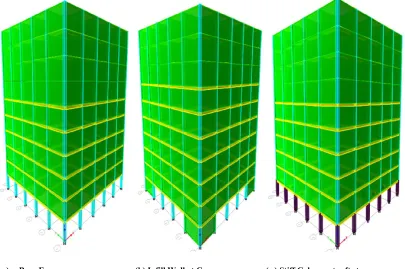
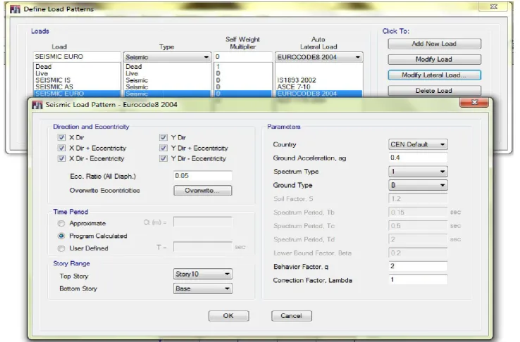
The modeled 3D frames of Bare Frame, Infill Wall at Corner and Stiff Column at soft storey are shown in Fig.7. The lateral force on the structure was calculated by using IS:1893(2002), ASCE 7-05 as shown in Fig. 5 and Fig.6 respectively and seismic load patternas per NZS 1170-2004 and EUROCODE 8-2004 are as shown in Fig. 8 and Fig.9 respectively.
[image:5.612.112.517.140.409.2]a) Bare Frame (b) Infill Wall at Corner ( c) Stiff Column at soft storey
[image:5.612.112.516.144.678.2]Fig. 7. ETABS Modeled 3D Structures
Fig.8. Defining Seismic Load Pattern as per NZS 1170 2004
RESULTS OF 2D FRAME ANALYSIS
[image:6.612.125.494.187.430.2]The deflected shape of bare frame (BF), Stiff columned at ground storey frame (SF) and Infill Wall at corner in ground storey frame (IF) are shown in Fig. 10. It is observed that deflection of bare frame (Fig.10.a) and stiffened column frame (Fig.10.c) cause the formation of a soft storey plastic mechanism which will lead to failure of structure. Infill wall at corner frame (Fig.10.b) deflects in a bending mode.
Fig.9 Defining Seismic Load Pattern as per EUROCODE 8 2004
(a) Bare Frame (BF) (b) Infill Wall at Corner Frame (IF)
8375 Dr. G. Nandini Devi, Comparative analysis of soft storey mechanismusing different codal standards
bare frame (BF), Stiff columned at ground storey frame (SF) and Infill Wall at corner in ground storey frame (IF) are shown in Fig. 10. It is observed that deflection of bare frame (Fig.10.a) and stiffened column frame oft storey plastic of structure. Infill wall at corner frame (Fig.10.b) deflects in a bending mode.
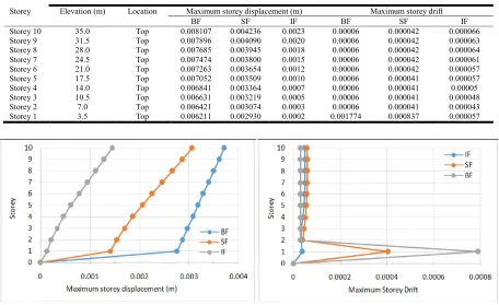
Table. 1 and Table.2 gives the storey response of maximum storey displacement and maximum storey drift
infill wall at corner frame and stiffened column frame due to lateral loading as per IS 1893:2002
respectively. From Table 1, it has been noted that roof deflection of SF and IF deflects 17.4% and 61.1% less when compared to BF. Storey drift of first storey at top of BF is 1.96 and 21.32 times higher than SF and IF respectively as per IS:1893 (2002). Deflection of BF as per IS:1893 (
loading 54.2% less when compared to ASCE 7
[image:6.612.100.508.466.711.2]Fig.12 shows maximum storey displacement and maximum storey drift as per IS: 1893(2002) and ASCE 7
Fig.9 Defining Seismic Load Pattern as per EUROCODE 8 2004
(b) Infill Wall at Corner Frame (IF) (c) Stiff Columned at Soft Storey (SF)
Fig.10. Deformed Shape
Dr. G. Nandini Devi, Comparative analysis of soft storey mechanismusing different codal standards
1 and Table.2 gives the storey response of maximum maximum storey drift of bare frame, infill wall at corner frame and stiffened column frame due to lateral loading as per IS 1893:2002 and ASCE 7-05 as been noted that roof deflection of SF and IF deflects 17.4% and 61.1% less when Storey drift of first storey at top of BF is 1.96 and 21.32 times higher than SF and IF respectively as per IS:1893 (2002). Deflection of BF as per IS:1893 (2002) lateral loading 54.2% less when compared to ASCE 7-05.Fig.11 and maximum storey displacement and maximum storey drift as per IS: 1893(2002) and ASCE 7-05 respectively.
Table 1. Maximum storeydisplacement and maximum storey drift as per IS: 1893(2002)
Storey Elevation(m) Location Maximum storey displacement (m) Maximum storey drift
BF SF IF BF SF IF
Storey 10 35.0 Top 0.003715 0.003068 0.001445 0.00003 0.000057 0.000046
Storey 9 31.5 Top 0.003609 0.002870 0.001284 0.00003 0.000058 0.000048
Storey 8 28.0 Top 0.003503 0.002667 0.001117 0.00003 0.000059 0.000049
Storey 7 24.5 Top 0.003396 0.002461 0.000948 0.00003 0.000059 0.000049
Storey 6 21.0 Top 0.003290 0.002256 0.000779 0.00003 0.000057 0.000047
Storey 5 17.5 Top 0.003184 0.002057 0.000617 0.00003 0.000054 0.000044
Storey 4 14.0 Top 0.003078 0.001869 0.000466 0.00003 0.000050 0.000039
Storey 3 10.5 Top 0.002972 0.001696 0.000331 0.00003 0.000044 0.000033
Storey 2 7.0 Top 0.002866 0.001546 0.000216 0.00003 0.000039 0.000031
Storey 1 3.5 Top 0.002761 0.001410 0.000130 0.000789 0.000403 0.000037
[image:7.612.76.532.247.526.2]Storey drift of first storey at top of BF is 1.96 and 21.32 times higher than SF and IF respectively as per IS:1893 (2002). Deflection of BF as per IS:1893 (2002) lateral loading 54.2% less when compared to ASCE 7-05.Fig.11 and Fig.12 showsmaximum storey displacement and maximum storey drift as per IS: 1893(2002) and ASCE 7-05 respectively.
Table 2. Maximum storey displacement and maximum storey drift as per ASCE 7-05
Storey Elevation (m) Location Maximum storey displacement (m) Maximum storey drift
BF SF IF BF SF IF
Storey 10 35.0 Top 0.008107 0.004236 0.0023 0.00006 0.000042 0.000066
Storey 9 31.5 Top 0.007896 0.004090 0.0020 0.00006 0.000042 0.000063
Storey 8 28.0 Top 0.007685 0.003945 0.0018 0.00006 0.000042 0.000064
Storey 7 24.5 Top 0.007474 0.003800 0.0015 0.00006 0.000042 0.000061
Storey 6 21.0 Top 0.007263 0.003654 0.0012 0.00006 0.000042 0.000057
Storey 5 17.5 Top 0.007052 0.003509 0.0010 0.00006 0.000041 0.000057
Storey 4 14.0 Top 0.006841 0.003364 0.0007 0.00006 0.000041 0.00005
Storey 3 10.5 Top 0.006631 0.003219 0.0005 0.00006 0.000041 0.000048
Storey 2 7.0 Top 0.006421 0.003074 0.0003 0.00006 0.000041 0.000043
[image:7.612.82.529.557.718.2]Storey 1 3.5 Top 0.006211 0.002930 0.0002 0.001774 0.000837 0.000057
Fig.11. Maximum storey displacement and maximum storey drift as per IS: 1893(2002)
Fig.12. Maximum storey displacement and maximum storey drift as per ASCE 7-05
RESULTS OF 3D FRAME ANALYSIS
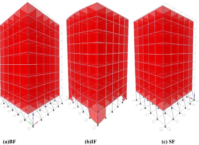
Results of maximum storey displacement and the various curves resulting from the analysis are briefed in the following text. Fig. 13 shows the deflected shape of three frames under seismic loading. From deflected shape, it has been noticed that storey failure mechanism as expected is more in BF when compared to other two frames. It has been also seen that deflection of corner columns of IF with infill differs from other free columns in soft storey.
(a)BF
[image:8.612.136.453.199.430.2]Fig. 13. Deformed Shape of the Frames to Lateral Loading
Table 3. Maximum Storey Displacement of Three Frames
Storey Elevation (m)
Storey10 35.0
Storey9 31.5
Storey8 28.0
Storey7 24.5
Storey6 21.0
Storey5 17.5
Storey4 14.0
Storey3 10.5
Storey2 7.0
[image:8.612.153.446.481.597.2]Storey1 3.5
Table 4. Maximum Storey Displacement of Three Frames
Storey Elevation (m) Location
Storey10 35.0 Top
Storey9 31.5 Top
Storey8 28.0 Top
Storey7 24.5 Top
Storey6 21.0 Top
Storey5 17.5 Top
Storey4 14.0 Top
Storey3 10.5 Top
Storey2 7.0 Top
8377 Dr. G. Nandini Devi, Comparative analysis of soft storey mechanismusing different codal standards
Results of maximum storey displacement and the various curves resulting from the analysis are briefed in the following text. Fig. 13 shows the deflected shape of three frames under loading. From deflected shape, it has been noticed that storey failure mechanism as expected is more in BF when compared to other two frames. It has been also seen that deflection of corner columns of IF with infill differs from other
Table 3 gives the maximum storey displacement three frame due to lateral loading in one direction (Y
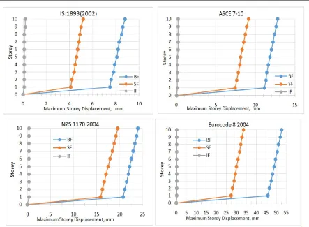
1893:2002 and ASCE 7-10.Table.4 gives the maximum storey displacement three frame due to lateral loading in one direction (Y-direction) as per NZS 1170 2004 and Eurocode 8 2004 respectively. Displacement in X-direction is very negligible. Comparison of deflection of three frames due to IS 1893:2002, ASCE 7-10, NZS 1170 2004 and Eurocode 8 2004 lateral loading is shown in Fig. 14.Comparis
deflection response to various standard loading is shown in Fig.15. Table. 5 gives structure response in terms of maximum storey displacement at top (mm), drift ratio (=Δ/H) and total base shear for various standards loading conditi
(b)IF (c) SF
Deformed Shape of the Frames to Lateral Loading
Maximum Storey Displacement of Three Frames
Elevation (m) Location
Maximum storey displacement (mm) as per IS:1893(2002) as per ASCE 7-10
BF SF IF BF SF IF
Top 8.8 5.2 0.2 12.8 9.1 0.2
Top 8.6 5.0 0.2 12.6 8.9 0.2
Top 8.5 4.9 0.1 12.4 8.7 0.2
Top 8.3 4.8 0.1 12.2 8.5 0.2
Top 8.2 4.7 0.1 12.0 8.3 0.2
Top 8.1 4.6 0.1 11.8 8.1 0.1
Top 7.9 4.5 0.1 11.6 8.0 0.1
Top 7.8 4.4 0.1 11.4 7.8 0.1
Top 7.6 4.2 0.1 11.3 7.6 0.1
Top 7.5 4.1 0.1 11.1 7.4 0.1
Maximum Storey Displacement of Three Frames
Location
Maximum storey displacement (mm)
as per NZS 1170 2004 as per Eurocode 8 2004
BF SF IF BF SF
Top 24.0 19.6 0.3 52.8 33.6
Top 23.7 19.2 0.3 52.0 32.9
Top 23.3 18.8 0.3 51.2 32.2
Top 23.0 18.4 0.3 50.5 31.6
Top 22.6 17.9 0.3 49.7 30.9
Top 22.2 17.5 0.3 48.9 30.2
Top 21.9 17.1 0.3 48.2 29.5
Top 21.5 16.7 0.3 47.4 28.9
Top 21.1 16.3 0.3 46.6 28.2
Dr. G. Nandini Devi, Comparative analysis of soft storey mechanismusing different codal standards
Table 3 gives the maximum storey displacement three frame due to lateral loading in one direction (Y-direction) as per IS 10.Table.4 gives the maximum storey displacement three frame due to lateral loading in one direction ) as per NZS 1170 2004 and Eurocode 8 2004 direction is very negligible. Comparison of deflection of three frames due to IS 1893:2002, 10, NZS 1170 2004 and Eurocode 8 2004 lateral loading is shown in Fig. 14.Comparisons of frames BF and SF deflection response to various standard loading is shown in Fig.15. Table. 5 gives structure response in terms of maximum storey displacement at top (mm), drift ratio (=Δ/H) and total base shear for various standards loading conditions.
[image:8.612.109.488.630.748.2]8378 International Journal of Current Research, Vol. 6, Issue, 09, pp.8370-8379, September,2014
[image:9.612.99.509.392.560.2]Fig. 14. Deflection Response Of Three Frames Subjected To Various Standard Seismic Lateral Loading
Fig.15. Comparisons of BF and SF Deflection Response to Various Standard Loading
Table 5. Structure Response for Loading as per IS 1893:2002, ASCE 7-10, NZS 1170 2004 AND Eurocode 8 2004
Structural Response Frame IS:1893 (2002) ASCE 7-10 NZS 1170 2004 Eurocode 8 2004
Maximum storey displacement at top (mm) BF 8.8 12.8 24 52.8
SF 5.2 9.1 19.6 33.6
IF 0.2 0.2 0.3 0.3
Drift Ratio = Δ/H of ground storey BF 0.00025 0.00036 0.00068 0.00015
SF 0.00015 0.00026 0.00056 0.00096
IF 0.0000057 0.0000057 0.0000086 0.0000086
Total Base shear (kN) BF 16053.2 17019.4 35752.7. 53370.6
SF IF
Comparison of Base shear of other standards with IS BF - 1.06 2.227 8.817
[image:9.612.73.537.597.728.2]Conclusion
In this study, G+9 Reinforced Concrete framed soft storey building was designed as per IS1893:2002 and was then analyzed for seismic lateral loading as per IS 1893:2002, ASCE 7-10, NZS 1170-2004 and EUROCODE 8-2004 methods using ETABS 2013 v 13.1.1. Following are the salient conclusions observed: The obtained result from ETABS software shows infill wall acts as the diagonal bracing in structure and the storey displacement in soft storey column transfers lateral force to adjacent infill wall panel. Stiffen columned frame also shows little soft storey mechanism when compared to Bare frame. Maximum storey displacement in 3D frame structure in descending order of (1) Bare frame model > (2) stiffen columned in soft first storey> (3) Infill wall at corners of soft first storey for Indian, American, New- Zealand and European Standards loading. Similarly in 2D frame structure maximum storey displacement and maximum storey drift values gives the same result. Hence use of infill walls at corners of soft first storey gives good resistant to lateral force. When comparing ETABS results of Indian, American, New-Zealand and European Standards, Base Shear values are in descending order of (1) European > (2) New-Zealand > (3) American> (4) Indian standards. Base shear value as per Eurocode is about 9 times greater than Indian Standard. Factors like Seismic zone factor, Importance factor, Response reduction factor, Fundamental period and Total mass of the structure differs from Standard to Standard. Hence the Base shear values also differ. Thereby affecting deformation of building.
REFERENCES
Amit S. Gawande “Seismic analysis of rc frame with soft ground storey”, IJPRET, 2013; Volume 1(8), pp: 213-223. Amit V. Khandve, “Seismic response of rc frame buildings with soft storey”, International Journal of Engineering
Research and Applications - Vol. 2, Issue 3, May-June
2012, pp 2100-2108.
Arturo Tena-Colunga “Review of the soft first story irregularity condition of buildings for seismic design”,
The Open Civil Engineering Journal, 2010, vol. 4, pp-
1-15.
Asce 7-05: “Minimum design loads for buildings and other structures”.
Dande P. S., Kodag P. B. “ Influence of provision of soft storey in rc frame building for earthquake resistance design”, International Journal of Engineering Research
and Applications, Vol. 3, Issue 2, March -April 2013,
pp.461-468.
Desai Pallavi T, Rajan A, “Seismic Performance of Soft Storey Composite Column”, International Journal of Scientific &
Engineering Research, Volume 4, Issue 1, January-2013,
ISSN 2229-5518.
ETABS - v9.7 ‘Integrated Building Design Software’ Manual, CSI, USA
Guney and E. Aydin, “The nonlinear effect of infill walls stiffness to prevent soft story collapse of rc structures”
The Open Construction and Building Technology Journal,
2012, 6, (Suppl. 1-M5) 74-80, 1874-8368.
IS 1893:2002, “Criteria for earthquake resistant design of structures”, Bureau of Indian Standards, New Delhi, India. Kasnale A S and Dr S S Jamkar, “Study of Seismic performance for soft basement of RCframed Buildings”, IOSR Journal of Mechanical & civil (IOSR-JMCE), ISSN: 2278-1684 PP: 47-51.
Mulgund GV 2011. “Seismic assesement of rc frame buildings with brick masonry infills”, International Journal of
Advanced Engineering Sciences and Technologies, Vol.
No. 2, Issue No. 2, 140 – 147.
Rahiman G. Khan, Prof. M. R. Vyawahare. “Push over analysis of tall building with soft stories at different levels”, International Journal of Engineering Research
and Applications, Vol. 3, Issue 4, Jul-Aug 2013,
pp.176-185.
SaraswatiSetia and Vineet Sharma, “Seismic Response of R.C.C Building with Soft Storey”, International Journal
of Applied Engineering Research, ISSN 0973-4562 Vol.7
No.11 (2012)
Wakchaure M.R, Ped S. P, “Earthquake Analysis of High Rise Building with and Without In filled Walls”, International Journal of Engineering and Innovative Technology
(IJEIT) Volume 2, Issue 2, August 2012.