Result Analysis of Efficient MIMO Framework for NOMA
Downlink and Uplink Transmission based on Signal
Alignment
Sonam Rai
M.Tech Scholar
Department of Electronics & Communication NRI, IIST Bhopal
Akhilesh Jain
Assistant Professor
Department of Electronics & Communication NRI, IIST Bhopal
ABSTRACT
In this paper, we aim to combine the schemes of multiuser applied in multiple-input multiple-output (MIMO) scheme with NOMA downlink communication systems. As multiple techniques can achieve multi-stream beam-forming coding diversity, the use of MIMO techniques brings flexible dimension for performance improvements. On the other hand, based on zero-forcing (ZF) technique, low complexity linear precoding scheme can reduce inter-interference when channel transmission. In particular, aiming to significantly enhance spectrum efficiency, we need to tackle the interference issue, which is exacerbated in heterogeneous network due to ultra dense node deployment as well as heterogeneity nature of various nodes. Specifically, we first study an optimal intra-cell inter-tier cooperation to mitigate interference between high power nodes and low power nodes.
Keywords
Non-orthogonal multiple access technique, uplink, spectral efficiency, fairness.
1.
INTRODUCTION
The widespread popularity of multimedia-friendly connected devices like smart phones and tablets is triggering explosive mobile video consumption and data traffic growth. Service providers are struggling to keep pace with the rapidly increasing demands from customers. Non-orthogonal multiple access (NOMA) procedure is broadly consider as one hopeful technology to get better the system capacity of future wireless communication systems [1-3]. The basic standard of NOMA is to provide several user by control area multiplexing at transmitter and successive interference cancellation (SIC) at receiver, which can accomplish the capability section of the downlink addictive white Gaussian noise channel and considerably outstrip the orthogonal multiple access (OMA) schemes.[5].
The conventional multiple access technique-orthogonal multiple access (OMA) schemes have been the dominant technology to employ the wireless systems. However, the conventional multiple access cannot satisfy high communication speed and load at the low data rate. Especially, 5th generation wireless systems require a faster and massive connections system to support transmission capacity and service billion of users. Non-orthogonal multiple access (NOMA) can provide significant performance gains over OMA schemes, it has been recognized as a viable solution of achieve spectrally efficient multiple access.
The basic idea of NOMA for multiple accesses is to introduce power domain, which the previous generation of mobile
networks have been relying only on the time/frequency/code domain. NOMA allocates a great amount of power to subcarriers with many users in weak conditions to facilitate a balance and trade-off between system throughput and users fairness. It means that NOMA scheme can meet the demanding 5G requirements of low latency and ultra-high connectivity.
As a promising paradigm in next generation networks, wireless heterogeneous networks bring heterogeneity into the network architecture. Specifically, we consider a two-tier downlink wireless heterogeneous network as shown in Fig. 1. Each cell is divided into several sectors, where one macro-node, e.g., mBS, and multiple micro-nodes, e.g., relay node (RN) and pBS, are deployed in each cell simultaneously. To differentiate from the cells that are created by macro-nodes, cells created by the micro-nodes are called micro-cells.
Compared to a macro-node, a micro-node typically transmits at a low power level and acts like a fully-featured mini-BS. Their reduced size and cost make them easily deployed for improving conditions in coverage holes and providing higher data rates at cell edge or in hotspots. UEs are uniformly distributed in the network, so that each UE can be served by either a macro-node or a micro-node, depending on the location and service requirement of the UE.
Fig.1 Wireless heterogeneous network
2.
SUPERPOSITION CODING
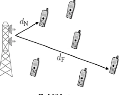
44 each user. When the far away user decodes the received
[image:2.595.318.534.75.227.2]encoded information, the interference from nearby users might be present. But the nearby users have a high link capacity gain with the base station, so it can decode the received information packet by subtracting the far user signals from the received signals. Fig 2 represents the two user SC (N-near the user, F-far user).
Fig.2 SC for two users
[image:2.595.60.260.155.313.2]The superposition coding is an acknowledged non orthogonal scheme. Capacity of scalar Gaussian broadcast channel can be achieved with SC [5]. In order to elaborate the performance of superposition coding, fig. 3 represents the signal constellation diagram of user 1 with higher transmitting power and user 2 with lower transmitting power and the constellation of user 1 is superimposed by user 2.
Fig.3 Encoding in SC (a) User 1's constellation (b) User 2's constellation (c) Superimposed signal constellation
diagram
3.
SUCCESSIVE INTERFERENCE
CANCELLATION
The SIC is the most powerful interference cancellation based scheme in terms of Bit-Error-Rate (BER) performance. The concept behind this scheme is that the users can decode the received signal efficiently. In SIC, users are aligned with respect to their signal strength. The receiver decodes the strongest signal first and cancelled it from the combined signal and later it decodes the signal which is having the weakest signal strength [6]. The SIC aims to improve system capacity and performance gain. Fig.4 illustrates the decoding of superimposed signals. As shown in the figure, after decoding the constellation point of user 1, constellation of user 2 will be decoded with respect to the user 1’s decoded constellation point.
Fig.4 Decoding in SC (a) Decoding user 1 (b) Decoding user 2
4.
PROPOSED METHODOLOGY
4.1
NOMA for Downlink
In NOMA downlink, the base station superimposes the information waveforms for its serviced users. Each user equipment (UE) employs SIC to detect their own signals. Figure 5 shows a BS and K number of UEs with SIC receivers. In the network, it is assumed that the UE1 is the closest to the base station (BS), and UEK is the farthest.
[image:2.595.56.280.406.528.2]The challenge for BS is to decide how to allocate the power among the individual information waveforms, which is critical for SIC. In NOMA downlink, more power is allocated to UE located farther from the BS and the least power to the UE closest to the BS. In the network, all UEs receive the same signal that contains the information for all users. Each UE decodes the strongest signal first, and then subtracts the decoded signal from the received signal. SIC receiver iterates the subtraction until it finds its own signal. UE located close to the BS can cancel the signals of the farther UEs. Since the signal of the farthest UE contributes the most to the received signal, it will decode its own signal first.
Fig.5 Downlink NOMA for K users
4.2
NOMA for Uplink
Uplink implementation of NOMA is slightly different than the downlink. Figure 6 depicts a network that multiplexes K UEs in the uplink using NOMA. This time, BS employs SIC in order to distinguish the user signals.
[image:2.595.316.542.489.617.2]requires connection between all the UEs which may be difficult to implement.
Fig.6 Uplink NOMA for K users
4.3
Flow Chart
In this proposed work explore the concept of non-orthogonal multiple access (NOMA) scheme for the future radio access for 5G. We first provide the fundamentals of the technique for both downlink and uplink channels and then discusses optimizing the network capacity under fairness constraints. We further discuss the impacts of imperfect receivers on the performance of NOMA networks. Finally, we discuss the spectral efficiency (SE) of the networks that employ NOMA with its relations with energy efficiency (EE). We demonstrate that the networks with NOMA outperform other multiple access schemes in terms of sum capacity, EE and SE.
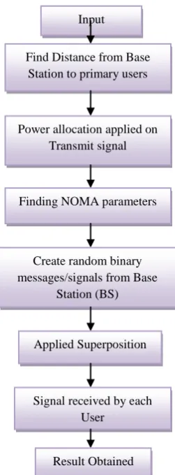
Fig.7 flow chart of proposed methodology
In the flow diagram of proposed system is show in fig.7. In this figure firstly provides the input into the proposed system than find the distance from base station to primary users.
After that Power allocation process is done. During this process power allocation applied on a signals. Than finding NOMA parameters such as power splitting factor, bandwidth splitting factor. Than Create random binary messages/signals from Base Station (BS) and signal of 'n' bits from BS to Primary User, User1 and User2 based on with power allocation after that applied superposition encoding and signals received by each users and lastly obtained the result.
5.
RESULTS
This paper gives efficient MIMO Framework for NOMA Downlink and Uplink Transmission Based on Signal Alignment results are shown below:
[image:3.595.318.543.211.387.2]Fig.8 graph representation of rate of user 1 and rate of user 2
[image:3.595.105.231.358.699.2]Fig.8 shows comparison of MIMO-NOMA and Basic method on behalf of rate of user 1 and rate of user 2. In this figure x axis shows rate of user 1 and y axis shows rate of user 2 in bps/Hz.
Fig.9 graph representation of spectral efficiency and energy efficiency
Fig.9 shows comparison of base paper method and proposed method on spectral efficiency and energy efficiency. In this figure x axis shows spectral efficiency in bit/sec/Hz and y axis shows the energy efficiency in bit/sec/Hz.
Input
Find Distance from Base Station to primary users
Power allocation applied on Transmit signal
Finding NOMA parameters
Create random binary messages/signals from Base
Station (BS)
Applied Superposition
Signal received by each User
[image:3.595.315.543.466.654.2]46
Fig.10 Graph representation of received power after NOMA apply
Fig.10 shows Graph representation of received power after NOMA apply. In this figure x axis show the data and y axis show the user.
Fig.11 Non orthogonal signal distribution
Fig.11 shows Non orthogonal signal distribution. The main advantages of non orthogonal schemes are its robustness against fading and cross-cell interference, and its flexibility in asynchronous transmission environments.
Fig.12 Graphical representation of transmission power and outage sum rate
Fig.12 shows Graphical representation of transmission power and outage sum rate. As can be seen from the figures, the proposed schemes can achieve larger outage sum rates compared to the base paper schemes, which demonstrates the superior spectral efficiency of NOMA.
Fig.13 Graphical representation of transmission power and outage probalities
Fig.13 shows Graphical representation of transmission power and outage probalities. The proposed schemes with precoding can achieve better outage performance than the base paper schemes without precoding, due to the efficient use of the degrees of freedom at the base station.
6.
CONCLUSION
NOMA can overcome a major problem of OMA based techniques that is not to allow frequency reuse within one cell, and is an advantageous technique for uplink transmission in future wireless communications. NOMA technology scheme applied from SISO to MIMO within systematic and mathematical approach. Specifically, after constructing system model, we demonstrate instantaneous weighted throughput and propose the problem formulation for resource allocation algorithm design. It can be implemented with some other diversity techniques like multiple-input-multiple-output (MIMO) or with coding schemes in order to increase the reliability and accordingly reduce the decoding errors. NOMA concept and proposed algorithm based on some problem formulation to improve the systems performance compared to OMA scheme.
7.
REFERENCES
[1] Ding, Zhiguo, Robert Schober, and H. Vincent Poor. “A general MIMO framework for NOMA downlink and uplink transmission based on signal alignment” IEEE Trans. on Wireless Communications 15.6 (2016): 4438-4454.
[2] Ding, Zhiguo, Fumiyuki Adachi, and H. Vincent Poor. “The application of MIMO to non-orthogonal multiple access” IEEE Trans. on Wireless Communications 15.1 (2016): 537-552..
[3] Tanaka, Al-Imari, Mohammed, et al. “Uplink non-orthogonal multiple access for 5G wireless networks” Wireless Communications Systems (ISWCS), 2014 11th Inter. Symposium on. IEEE, 2014.
communication” IEEE Trans. on Comm. 64.12 (2016): 5162-5175.
[5] Sun, Qi, et al. “On the ergodic capacity of MIMO NOMA systems” IEEE Wireless Communications Letters 4.4 (2015): 405-408.
[6] Wei, Zhiqiang, et al. “A survey of downlink non-orthogonal multiple access for 5G wireless communication networks” arXiv preprint arXiv:1609.01856 (2016).
[7] Aleem, Saniya, and Arathi R. Shankar. “QoS Analysis of MIMO-NOMA for Uplink Transmission using Successive Bandwidth Division” (2017).
[8] Murti, Fahri Wisnu, Rahmat Faddli Siregar, and Soo Young Shin. “MMSE for Uplink MIMO-NOMA Decoding with Practical SIC Design” (2017): 369-370.
[9] Z. Ding and H. Poor, “A general framework of precoding design for multiple two-way relaying communications” IEEE Trans. vol. 61, no. 6, pp. 1531–1535, Mar. 2013.
[10] M. Peng, C. Wang, J. Li, H. Xiang, and V. Lau, “Recent advances in underlay heterogeneous networks:
Interference control, resource allocation, and self-organization” IEEE Commun. Surveys Tuts., vol. 17, no. 2, pp. 700–729, Second quarter 2015.
[11] “C-RAN: The road towards green RAN” China Mobile Res. Inst., Beijing, China, Oct. 2011, White Paper, ver. 2.5.
[12] Z. Ding, P. Fan, and H. V. Poor, “Impact of user pairing on 5G non-orthogonal multiple access” IEEE Trans. Vehicular Technology, (submitted) Available on-line at arXiv:1412.2799.
[13] M. Haenggi, “Stochastic Geometry for Wireless Networks” Cambridge University Press, Cambridge, UK, 2012.
[14] J. Venkataraman, M. Haenggi, and O. Collins, “Shot noise models for outage and throughput analyses in wireless ad hoc networks” in Proc. IEEE Military Comm. Conference, Washington, DC, USA, Oct. 2006.