Defect Analysis for Sand Casting process (Case Study in foundry of
Kombolcha Textile Share Company)
Wossenu Ali
Wollo University, Kombolcha Institute of Technology, Mechanical Engineering Department, Kombolcha, Ethiopia
---***---Abstract -This research aimed to identify the cause of casting defect and to suggest possible remedies in order to produce conforming casting product in the foundry of Kombolcha textile share company, Ethiopia. During casting defect analysis, the common casting defects blowholes, pinholes and shrinkage were identified. The major and minor process variables which were responsible for each casting defects were indicated using fishbone diagram. For analysis of possible causes, Experiments were conducted for moulding sand to determine clay content and grain fineness number (GFN). For defective part, composition analysis using spectrometer was also done. Analysis showed that high clay content (52.7%) of moulding sand, wrong gating system design, incorrect pattern design and unknown pouring temperature were responsible for the defects. Experiment was conducted for remedial actions using reclaimed sand with grain fineness number 40.19 and clay content of 1.5%, for correct gating system and pattern design for casting of brake casing of weaving machine. Good results were obtained with exception of difficulty in pattern removal during mould making due to coarseness of the sand. Finally, the possible remedies for the defects were suggested.
Key Words: - Sand Casting, Casting Defects, defect analysis, fishbone diagram, and gating system.
1. INTRODUCTION
Metal casting is one of the primary manufacturing processes which uses to produce simple or complex products and is the only method uses to produce massive objects in one single piece by pouring molten metal into mould or die cavity, and allowing it to solidify into shape of the cavity[13].Metal casting process is a complex process with several sub-processes, such as patternmaking, mould and core making, melting and pouring, heat treatment and cleaning, finishing, which in turn have several process variables[7].To produce product within customers acceptance specification, proper control of varies process variable at each process stage within the required level is important to produce conforming
casting product. Deviation of any process parameter will cause one or more casting defects on the product.
A few manufacturing industries are found in Ethiopia in which casting process is the one that uses to produce metallic parts. These parts use for internal customers who wants to substitute their broken spare parts. Since the process is supported by shop-floor trial and there is shortage of skilled workers, the casting products produced are not quality product to satisfy customers need. Solving this problem in these foundries is important to satisfy customers need.
Casting process in foundry of Kombolcha textile Share Company produces parts such as Armature disk, front flange, real flange, and pulley of different size, cast iron and Aluminum ingot of different size, machine frame and others by using Cast iron and Aluminum as a casting material. Since this foundry is supported by shop floor trial, parts produce in this foundry are most of the time defective products. Therefore, identify the cause of casting defect and suggesting possible remedies to quality enhancement is important for the company itself to increase its productivity with having fast spare part supply for maintenance service and also to satisfy its external customers.
2. Literature Review
Thakker [18] revised different researches which involved in casting defect analysis and their quality improvement. They summarized causes and remedies suggested by different researchers on major sand-casting defect, shrinkage cavities, moulding material defects, pouring metal and metallurgical defect. Aniruddha Joshi and L.M. Jugulkar [1] did casting defect analysis for foundry which produces automotive components like engine flange, cylinder head cover and bearing housing. They used the quality control tools such as check sheet to collect data, Pareto diagram to identify the major defects and cause and effect diagram to identify the cause of the defect.
3. Methodologies and Materials
Here, casting defect analysis was done by following steps set up in the casting defect analysis map as shown figure.1 below. During analysis necessary dates were collected from the foundry, experiments were conducted for moulding sand (such as sieve analysis, clay content test) and composition analysis for casting material.
Figure.1 Defect analysis map [3]
3.1.
Detection of the defect
Almost all product of casting in this foundry are defective products. From the evidence, only a few are acceptable casting product with certain tolerance, the majorities are rejected product. As shown in figure 2.
a) Shrinkage due to fast
solidification at thin section b) Shrinkage due to
Remedy Analyze
possible cause
Take corrective action
Defect
analysis complete is
defect correct? Detection
of defect
Decide possible causes Identify the
symptoms
Define the defect
No
Yes
Figure.2 a, b, c and d are examples of casting defects commonly occurred in the foundry
3.2. Identify the Symptoms and defining defects
From the symptoms, let’s define the kind of defects.
Table 1. Symptoms commonly absorbed and related defect types
No. Symptoms Absorbed Kind of casting defect
1. Numerous holes of small diameter
(less than 2mm) Pinholes
2. Smooth and round holes
(about 3mm in diameter) Blowholes 3. Large and rough void or depression,
Holes at the joint section Shrinkage cavity
4. Embedment of sand
on casting surface Burn-on
3.4. Decide possible cause
Fish bone diagram is one of the methods for identifying causes of the defects. The diagram indicates all the possible major and minor causes which are responsible for the occurrence of the above listed defects where there is any deviation from their acceptance level. The following are the fishbone diagrams for those defects occurred in this foundry.
Blowholes
Pinholes
d) Shrinkage at the joint of section
[image:3.595.111.486.434.569.2]Figure 3. Cause and effect diagram for blowholes and pinholes
[image:4.595.54.549.496.739.2]Figure 5. Cause and effect diagram for sand burn on
3.5. Analysis of possible cause
In order to identify from all sub-causes shown in fishbone diagram, which one is responsible for the defect indicated, detail examination of process parameters in this foundry is important. Therefore, to analyze possible causes of the defects, experimental test to some measurable variables and practical examinations of existing foundry work were done.
The following were Experimental tests
1. Clay content test
2. Grain fineness number test
3. Chemical Composition analysis for sample defective casted metal
Testing of clay content
The test was conducted in foundry laboratory of Federal Micro and small enterprise development agency, Ethiopia.
Laboratory equipment used: clay washer, oven drier and weighing scale.
Chemical used: 25c.c standard solution of (NaOH) sodium hydroxide
The clay content test was done for foundry sand (see figure 5, below) which use in this foundry.
100g of sand sample was taken and results the following;
Clay content = _
In percentage, 52.7% of molding sand is clay and 47.3% of molding sand is silica grain. Based on clay content test, clay content of 52.7% is extremely contradictory to the recommended percentage of clay for different types of moulding sands which uses for mould making process. Based on their classification, maximum clay content is not more than 2% for high silica sand and up to 10% for natural moulding sand [13].
Grain fineness number (GFN) test
This experiment was conducted next to clay content test for silica grains of 47.3g left after clay removal.
Laboratory equipment used: Sieve shaker, weighing scale.
Sieve analysis was done for 47.3g of silica sand grains. The test was carried out in power driven shaker consisting of number of sieves having varying and known number of meshes fitted one over the other. Shaking was for about 15-minutes. Finally, the weight of silica grain on each sieve was weighted and the following result was obtained. (experimental result is show in table 2 below)
Figure.8 Photo during shaking of sand in sieve shaker and weighing of each sieve with grains on it.
Figure.5 The moulding sand which use in this foundry
Grain fineness number (GFN) =
Grain fineness number (GFN) 16.74 determined by experiment is very small number, it indicates this sand is very coarse which has very small fineness number less than the average fineness number which varies for cast iron from 45-65 and light alloys(e.g.Aluminium) 70-100 [13].
Table 2. Measured and calculated sieve analysis data
Chemical Composition analysis for sample defective product
The test was conducted in foundry laboratory of Akake basic metals industry, Ethiopia.
Laboratory equipment used: Spectrometer
[image:7.595.45.554.274.503.2]Sample of defective cast iron part was taken and the following composition analysis was found.
Table.3 Composition of cast iron sample
C Si Mn P S Cr Mo Ni Al Co Cu Nb
3.67 2.00 0.482 0.183 0.164 0.074 <0.003 0.057 0.025 <0.009 0.092 <0.005
Ti V W Pb Sn Mg As Zr B Fe
0.027 0.016 <0.040 <0.010 0.006 <0.002 0.016 <0.003 <0.001 93.1
Composition of metal determines the desired strength and metallurgical structure of the parts to casted. In case of ferrous casting, it is necessary to know the percentage of Carbon, Silicon, Sulphur, Manganese, and Phosphorous
Sieve No. Diameter of Sieve hole Weight of sieve
Weight of Retained
sand sieve
Weight retained sand Multiplying
Factor Product
(g) (%)
6 mesh 3.35mm 482.52 488.89 6.37 13.46% 2 26.92
12 mesh 4.70mm 407.42 416.57 9.15 19.34% 6 116.04
20 mesh 850mm 370.84 389.30 18.46 39.02% 12 468.24
30 mesh 600 µm 349.17 355.29 6.12 12.95% 20 259
40 mesh 425 µm 339.26 342.01 2.75 5.82% 30 174.6
50 mesh 300 µm 331.06 332.54 1.48 3.14% 40 125.6
70 mesh 212 µm 307.73 308.84 1.11 2.34% 50 117
100 mesh 150 µm 306.12 306.91 0.79 1.68% 70 117.6
140 mesh 106 µm 306.14 306.71 0.57 1.21% 100 121
200 mesh 75 µm 300.34 300.71 0.37 0.79% 140 110.6
270mesh 5.3 µm 293.76 293.84 0.08 0.17% 200 34
Pan 276.56 276.563 0.003 0.01% 270 2.7
contents. To get the actual structure of cast iron, carbon in the range of 3.5-4%,silicon in the range of 1-3%,manganese in the range of 0.4-1%,phosphrous no to exceed 1% and Sulphur kept below 0.05%.[13]
The above spectroscopic analysis indicates that all the required elements are in correct composition range to produce parts from cast iron with actual structure and without shrinkage defect which result from unsuitable metal composition.
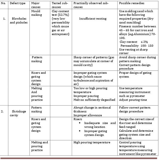
[image:8.595.33.567.257.795.2]All major causes and sub-causes indicated on the fish-bone diagram were experimentally tested and practically absorbed. Causes which were responsible for those defects were identified and possible remedies were suggested as shown in the table below.
Table 1. Shows defect type, the major cause, tested sub-causes, observed sub-causes and possible remedies
No. Defect type Major
causes
Tested sub-causes
Practically observed sub-causes
Possible remedies
1. Blowholes and pinholes
Mould
making Clay content test (52.7%) (very low permeability which cause gas or air entrapment)
Insufficient venting
Use molding sand which have the following required properties (dry sand moulding)
Fineness number between 45 – 65 for cast iron and alloys (e.g.Aluminium) 70-100.
Clay content ≤ 2% Permeability 100- 150 Use venting at sharp corner
Pattern
making Sharp corner of patterns (gas may accumulate at corner of mould cavity)
Avoid sharp corner during pattern making
Correct pattern design procedure
Risers and gating system design
Improper gating system design (which cause
turbulence and aspiration of air)
Proper design of gating system
Melting And pouring practice
Too low or high pouring temperature
Improper pouring
Melt no sufficiently degasified
Use temperature measuring instrument such as pyrometer Adjust pouring time
2. Shrinkage cavity
Pattern making
Abrupt change in sectional thickness
Improper allowance
Follow correct pattern design procedure Risers and gating system design Risers
Inadequate size and wrong location
Improper gating system design
Design the correct size of the riser and determine feed ranged
Calculate and determine gating system size and direction
Melting and pouring practice
High pouring temperature Control pouring
3.
Sand burn on
Mould
making High moisture content of sand (this is due to high clay content)
Use sand with low cay content.
Use of coal dust Melting and
pouring
practice High pouring temperature
Control pouring temperature using temperature measuring instrument like pyrometer
Notice. Those major cause and sub-cause which were on correct design, composition and working procedure are not listed in the above table.
But for sand burn-on sub-causes such as amount of low melting impurities and lustrous carbon content were not tested due to absence of gas determinator. Here conclusion was done for moisture content with respect to clay content and unknown pouring temperature.
4. Casting experiment for remedial actions
Casting experiment was done for one of the common products, brake casing of the weaving machine, in foundry of kombolcha textile Share Company. The following remedial actions were done for this selected product.
Figure 9. Isometric view of brake casing
4.1. Change of moulding sand
Reclaimed sand (used sand) with the following properties was brought from foundry of federal medium and small enterprise agency, Ethiopia.
Grain fineness number = 40.19
[image:9.595.223.373.358.476.2]Clay content = 1.5%
4.2. Pattern design
The pattern was designed and manufactured for selected product by following the correct pattern design procedure. It results the split pattern as shown below.
Type: split pattern Material of pattern: Aluminum
Allowance: Contraction allowance of 10.5mm/M and Machining allowance of 3mm were given for cast iron [13] .
[image:10.595.196.425.571.760.2]a) Left part of split pattern b) Right part of the split pattern
Figure 11. Isometric view of split pattern
4.3. Design of gating system
To avoid turbulence and to have smooth metal flow, the gating system for the selected product was designed. Here design analysis for determination of pouring cup, sprue size, choke area, runner size, pouring time required, average filling time of the casting and effective metal head of the casting was done. At the end, appropriate gating system that is pressurized gating system with ratio 4:1 was selected and based on sprue design, taper sprue cutter was manufactured. The following figure is resulted dimensions of sprue, sprue well, and two gates for gating ratio 4:1.
Dimensions are in mm
Figure 12. Dimension of Sprue, Sprue well and two gates in mm for gating ratio 4:1
8
62.32
16 31.16
35.84
Procedures for Experiment
Pattern was manufactured as shown figure (a) below based on designed dimension. Sprue cutters (figure.b below) was manufactured based on the dimension of sprue as shown in figure 12.Starting from pattern making up to finishing, the following are casting steps which was done.
a)
Split Patterns b) Sprue cutter forgating ratio 4:1 c) During mould making
e) Assembled mould ready for pouring
f) Melting process g) Pouring process
i ) After sand removal by hand
grinding h) After shake out
5.1. Results and discussion
Three experiments were conducted. Testing of moulding sand, clay content test (52.7%) and grain fineness number (GFN) (16.74) indicated that the sand in this foundry is not moulding sand. It cannot use for mould making process. It was main reason for the defects to occur. Therefore, it must be removed and substitute by other moulding sand.
During metal composition analysis of defective parts, alloys content was in the required range. Therefore, it was not responsible for the defects to occur.
Incorrect pattern design, wrong gating system design and uncontrolled melting process were absorbed which were the causes for defects. In order to minimize those problems, correct working procedure must be followed.
For remedial actions, experimental test was done using other moulding sand, correct pattern design and gating system design for brake casing of weaving machine. But the problem absorbed during the experiment were difficulty in mould making and rough casting surface due to coarseness of this reclaimed sand and sand burn on also absorbed.
6. Conclusions
From defect analysis, the defects in this foundry were gas porosity (blowholes and pinholes) and shrinkage porosity. The main reason for these defects was high clay content (52.7%) of the previous sand, unknown melting temperature, incorrect gating system and pattern design.
Experiment for remedial action resulted with conforming casting product for designed pressurized gating system (gating ratio 4:1). This is because the flow is streamlined and defect due to turbulence is avoided, the sand used for mould making has high permeability therefore no air or gas entrapment which causes blowholes or pinholes. The pattern and gating system design were controlled to avoid blowholes, pinholes and shrinkage.
For production of quality casting parts, this foundry must provide other moulding sand and control of other process parameters during pattern making, gating system design and pouring practice is important.
Acknowledgements
I am appreciatively thankful to Wollo university research and Community service, for sponsoring the research. I am equally grateful to Kmobolcha textile Share Company for their full collaboration for this research work, Akaki basic metals industry their contribution to test composition of metal by spectrometer and Federal Micro and Small enterprise development agency for permission of their sand testing equipment to test moulding sand.
REFERENCES
[1]. Aniruddha Joshi and L.M.Jugulkar,Investigation and analysis of metal casting defects and defect reduction by using quality control tools,international journal of mechanical and production engineering,volume 2,issue-4,April-2014.
[2] A.P.More, Dr.R Baxi, Dr.S.B.Jaju, Review of casting defect analysis to initiate the improvement process, int.J Engg, vol.4, pg (292-295), (2011)
[3]. B.chokkaligam and S.S.Mahammed Naziruden,analysis of casting defect through defect diagnostic study Approach,Journal of engineering annals of faculty of engineering Hunedoara,2009
[4].Dr.B.Ravi, Casting simulation and Optimization: Benefits, Bottlenecks, and best practices, Indian foundry journal, (2008)
[5].Dr.B.Ravi, Durgesh Joshi, feadibility analysis and optimization Driven by casting simulation, Indian journal, (2007)
[6]. Dr.D.N.Shivappa, Mr.Rohit and Mr.Abhijit Bhattacharya, analysis of casting defects and identification of remedial measures-a diagnostic study, international journal of engineering Inventions,2012.
[7].Dr.Hathibelagel Roshan, process optimization as a tool in the analysis of steel casting defects, Maynard steel casting company
[8].G.S.Cellini, L.Tomesani, Metal head-dependant HTC in sand casting simulation of aluminum alloys, journal of achievements in materials and manufacturing engineering,vol.29,pg(47-52),(2008)
[9]. I.Vaskava, D.Fecko and L.Eperjesi, Comparison of simulation programs Magmasoft and Nova flow & Solid in terms of results accuracy, Archives of foundry Engineering,2011.
[10] L.A.Dobrzanski, M.Krupinski, J.H.Sokoski, P.Zarychta, A.Wlodarczyk-Fligier, Methodology of analysis of casting defects, journal of achievements in materials and manufacturing engineering,vol.18,pg(267-270),(2006)
[11].L.A.Dobrzanski, M.Krupinski, P.Zarchta, R.Maniara, analysis of influence of chemical composition of Al-Si-Cu casting alloy on formation of casting defects, journal of achievements in materials and manufacturing engineering,vol 21,pg(53-56),(2007)
[12] L.A.Dobrzanski, M.Krupinski, R.Maniara, J.H.Sosolowski, computer aided method for quality control of automotive Al-Si-Cu cast components, journal of achievements in materials and manufacturing engineering,vol.24,pg(151-154),(2007)
[13]. P L Jain, Principle of foundry technology, Tata McGraw-Hill, New Delhi, fourth edition,2007.
[14]. P.Prabhakara, Rao,G.Chakravethi, A.C.S.Kumar and B.Balakrishna, Application of casting simulation for sand casting of a crusher plate, International journal of thermal technologies,vol.1.no.1(Dec.2011)
[15]. Prof.Tushar M.paltel and Mr.Ankit Doza, Analysis and validation of gravity die casting process using procast, IJAIEM, Vol.2.Issue,April 2013.
[16]. Rajesh Rajkahe and J.G.Khan, Defects, causes and their remedies in casting process, International journal of research in advent technology,vol.2,No.3,March 2014.
[17]. R.S.Ransing, M.N.Srinivasan, R.W.Lewis, ICADA: Intelligent computer aided defect analysis for casting ,journal of intelligent manufacturing,vol.6,pg(29-40),(1995).
[19].V.V.Mane, Amit Sata, M.Y.Khire, New approach to casting defects classification and analysis supported by simulation
BIOGRAPHY
Mr. Wossenu Ali Lecturer, Wollo University,
Kombolcha Institute of Technology, Mechanical Engineering Department